HealthCare Information RM22III User manual
Android RoomMate
LCD HC TV
Operations Manual
MODEL NUMBERS RM22III, RM26III, RM32III and RM42III REVISION 2.0


-------------------------------------------------------------------------------------GEN III OPERATIONS MANUAL
HealthCare Information, LLC
3
TABLE OF CONTENTS
SAFETY INSTRUCTIONS 5-6
PACKAGE CONTENTS 7
PRODUCT INTRODUCTION 8-11
IR REMOTE 8, 9
LEFT SIDE INPUT PANEL 10
FRONT PANEL KEYPAD 10
RIGHT SIDE KEYPAD 10
REAR JACK PANEL 11
INSTALLATION 12-13
ANTENNA 12
COMPOSITE A/V 12
PC 12
EXTERNAL SPEAKERS 12
PILLOW SPEAKER(S) 12, 13
THIRD PARTY CONTROLLERS 13
SOFTWARE UPDATES 13
SETUP AND OPERATION 14-28
IR BATTERIES 14
GETTING STARTED 14-16
QUICK SETUP 14
QUICK SETUP WITH CLONE 14, 15
FUNCTION CODES 15
CHANNEL SCAN 15, 16
PILLOW SPEAKER SETUP 16
DATE AND TIME 16
BASIC TV SETUP MENU 17-25
PICTURE 17
PICTURE MODE 17
CONTRAST 17
BRIGHTNESS 17
SHARPNESS 17
TINT (HUE) 17
COLOR 17
COLOR MODE 17
ZOOM MODE 17
NOISE REDUCTION 17
AUDIO 18-19
SOUND MODE 18
PILLOW SPK ADVANCE 18
PS ¼” MAX VOL 18
PS 6-PIN MAX VOL 18
TV MAX VOL 18
TV MIN VOL 18
POWER ON VOL. 18
BASS 18
TREBLE 18
BALANCE 18
MTS 18
SPEAKER MODE 18, 19
PILLOW SPK1 MODE 19
PILLOW SPK2 MODE 19
TIME 19, 20
SLEEP TIMER 19
TIME ZONE 19
DST 19
TIME FORMAT 19
AUTO SYNC 19
CLOCK 19
POWER ON/OFF 19, 20
OPTION 20-23
MENU LANGUAGE 20
TRANSPARENT 20
OSD TIME OUT 20
CLOSED CAPTION 20, 21
CC MODE 20
BASIC SELECTION 21
ADVANCED 21
OPTION 21, 22
RESTORE DEFAULT 22
INPUT LABEL 22
BANK SEL. 22
IR BAND 22
HCI SETUP 22, 23
LED MODE 22
LED BLINK 22
SERIAL CONTROL 22
AC POWER ON 21
LOCK 23
CHANGE PASSWORD 23
SYSTEM LOCK 23
INPUT BLOCK 23
US V-CHIP 23
CANADA V-CHIP 23
CHANNEL 24, 25
TV SOURCE 24
AUTO SCAN 24
BANK 24
SHOW/HIDE & EDU 24
CH NO. 24
LABEL 25
DTV SIGNAL 25
FUNCTION MENU 26-28
CHANNEL LIST 26
ADVANCE MENU 26
LOAD FROM USB 26
SAVE TO USB 26
MSTAR FW UPDATE 26

-------------------------------------------------------------------------------------GEN III OPERATIONS MANUAL
HealthCare Information, LLC
4
POWER ON SETUP 26-28
KEYPAD SELECT 26
POWER ON SOURCE 27
POWER ON CHANNEL 27
POWER ROLLING 27
SOURCE ROLLING 27
KEYPAD LOCK 27
VCT TABLE SELECT 27
LED OPERATE MODE 27
CEC POWER FUNCTION 28
OTHER 28
INPUT AUTO DETECT 28
RESET ANDROID 28
RESET ANDROID MODE 28
MESSAGE SOUND ON/OFF 28
MESSAGE SOUND VOLUME 28
ANDROID™ OPERATING SYSTEM 29-33
SETTINGS APP 29
ETHERNET 29
WIRELESS 30
STANDARD APPS AND FEATURES 30, 31
TV 31
APPS 30, 31
SPEAKER 30
DVD 30
AV REAR 30
AV SIDE 30
FILE BROWSER 31
TVO BROWSER 31
ANDROID PDF 31
VIEWER
APP PLACE 31
DEV TOOLS 31
INFO 31
REMOTE RDP 31
EDU 31
GAMES 31
MOVIES 31
PRESCRIBED CONTENT 31
AUDIO 31
PICS 31
NET 31
MY HEALTH 31
USB 31
SOFTWARE UPDATES 32
WHITE BOARD MESSAGES 32
WHITE BOARD VIDEO 32
LOGO SETTING 32
HOME PAGE 33
MANAGING APPS 33
HARD DRIVE 33
RETURN TO TV 33
MENU TREE 34, 35
PILLOW SPEAKER OPERATION 36
DVD/IPTV PILLOW SPEAKER CONTROL 37
PARENTAL CONTROL 38, 39
TV RATINGS 38, 39
UNITED STATES 38
CANADA ENG RATINGS 38
CANADA FRE RATINGS 39
SETUP 39
BANKS 40
ACCESSORIES 41
SPECIFICATIONS 42-46
DIMENSIONS RM22III 42
DIMENSIONS RM26III 43
DIMENSIONS RM32III 44
DIMENSIONS RM42III 45
GENERAL 46
WARRANTY 47

WARNING
To reduce the risk of fire or electric shock, do not expose this apparatus to rain or moisture and this apparatus shall not be exposed to dripping or splashing and
no objects filled with liquids, such as vases, shall be placed on the apparatus.
Do not use this LCD TV Monitor near water. For example: avoid placing it near a bathtub, washbowl, kitchen sink, or laundry tub, in a wet basement, or near a
swimming pool, etc.
This apparatus shall be connected to a mains socket outlet with a protective earthing connection.
The mains plug of this apparatus must remain readily operable.
Advertisement:
Pour réduire le risque du feu ou de décharge électrique, n’exposez pas cet appareil à la pluie ou à l’humidité. L’appareil ne sera pas exposé à l’égoutture ou
l’éclaboussement et aucun objet remplis de liquides, tels que des vases, ne seront placés sur l’appareil.
NOTE TO CABLE TV INSTALLER
This reminder is provided to call the cable TV installer’s attention to Article 820-40 of the National Electric Code (U.S.A.). This code provides guidelines for
proper grounding and, in particular, specifies that the cable ground shall be connected to the grounding system of the building as close to the point of the cable
entry as practical.
REGULATORY INFORM
This equipment generates, uses and can radiate radio frequency energy, and if not installed in accordance with this instruction manual, may cause harmful
interference to radio communications. However, there is no guarantee that interference will not occur in a particular installation. If this equipment does cause
harmful interference to radio or television reception, which can be determined by turning the equipment off and on, the user is encouraged to try to correct the
interference by on or more of the follow measures:
1. Increase the separation between the equipment and receiver.
2. Consult the dealer or an experienced radio/TV technician for help.
CAUTION
Do not attempt to modify this product in any way without written authorization from HealthCare Information, LLC. Unauthorized modification will void the
warranty of the product.
COMPLIANCE
The party responsible for this product’s compliance is:
HealthCare Information, LLC, 113 Commerce Blvd., Loveland, OH 45140, USA. Phone 513-271-8100.
HealthCare Information, LLC 5

-------------------------------------------------------------------------------------GEN III OPERATIONS MANUAL
HealthCare Information, LLC
6
IMPORTANT SAFETY INSTRUCTIONS
1) Read these instructions.
2) Keep these instructions.
3) Heed all warnings.
4) Follow all instructions.
5) Do not use this apparatus near water.
6) Clean only with dry cloth.
7) Do not block any ventilation openings. Install in accordance with the manufactures instructions.
8) Do not install near any heat source such as radiators, heat registers, stoves, or other apparatus (including amplifiers)
that produces heat.
9) Do not defeat the safety purpose of the polarized or grounding type plug. A polarized plug has two blades with one
wider than the other. A grounding type plug has two blades and a third grounding prong. The wide blade or third prong is provided
for your safety. If the provided plug does not fit into you outlet, consult an electrician for replacement of the obsolete outlet.
10) Protect the power cord from being walked on or pinched particularly at plugs, convenience
receptacles, and the point where they exit from the apparatus.
11) Only use attachments/accessories specified by the manufacturer.
12) Use only with the cart, stand, tripod, bracket, or table specified by the manufacturer, or sold
with the apparatus. When a cart is used, use caution when moving the cart/apparatus
combination to avoid injury from tip-over.
13) Unplug this apparatus during lightning storms or when unused for long periods of time.
14) Refer all servicing to qualified service personnel. Servicing is required when the
apparatus has been damaged in any way, such as power-supply cord or plug is
damaged, liquid has been spilled or objects have fallen into the apparatus, the
apparatus has been exposed to rain or moisture, does not operate normally, or has
been dropped.
IMPORTANT SAFEGUARDS FOR YOU AND YOUR NEW PRODUCT
YOUR NEW PRODUCT HAS BEEN MANUFACTURED AND TESTED WITH YOUR SAFETY IN MIND. HOWEVER, IMPROPER
USE CAN RESULT IN POTENTIAL ELECTRICAL SHOCK OR FIRE HAZARDS. TO AVOID DEFEATING THE SAFEGUARDS
THAT HAVE BEEN BUILT INTO YOUR NEW PRODUCT, PLEASE READ AND OBSERVE THE FOLLOWING SAFETY POINTS
WHEN INSTALLING AND USING YOUR NEW PRODUCT, AND SAVE THEM FOR FUTURE REFERENCE. OBSERVING THE
SIMPLE PRECAUTIONS DISCUSSED IN THE MANUAL CAN HELP YOU GET MANY YEARS OF ENJOYMENT AND SAFE
OPERATION THAT ARE BUILT INTO YOUR NEW PRODUCT.
REAL TIME CLOCK BACKUP BATTERY
CAUTION –Danger of explosion if battery is incorrectly replaced. Replace only with the same or equivalent type.

-------------------------------------------------------------------------------------GEN III OPERATIONS MANUAL
HealthCare Information, LLC
7
Package Contents
After opening, carefully check the package contents:
HD-Android™LCD TV
Power Cord
IR Remote are shipped per order
Manuals are shipped per order*
This manual covers the following models:
RM22III 22-Inch LCD Android™Powered TV
RM26III 26-Inch LCD Android™Powered TV
RM32III 32-Inch LCD Android™Powered TV
RM42III 42-Inch LCD Android™Powered TV
NOTE: Instructions in this manual apply to all of the above listed sets unless stated
otherwise.
*The latest version of the manual can be downloaded from www.hcic.com
-------------------------------------------------------------------------------------GEN III OPERATIONS MANUAL
HealthCare Information, LLC
8
PRODUCT INTRODUCTION
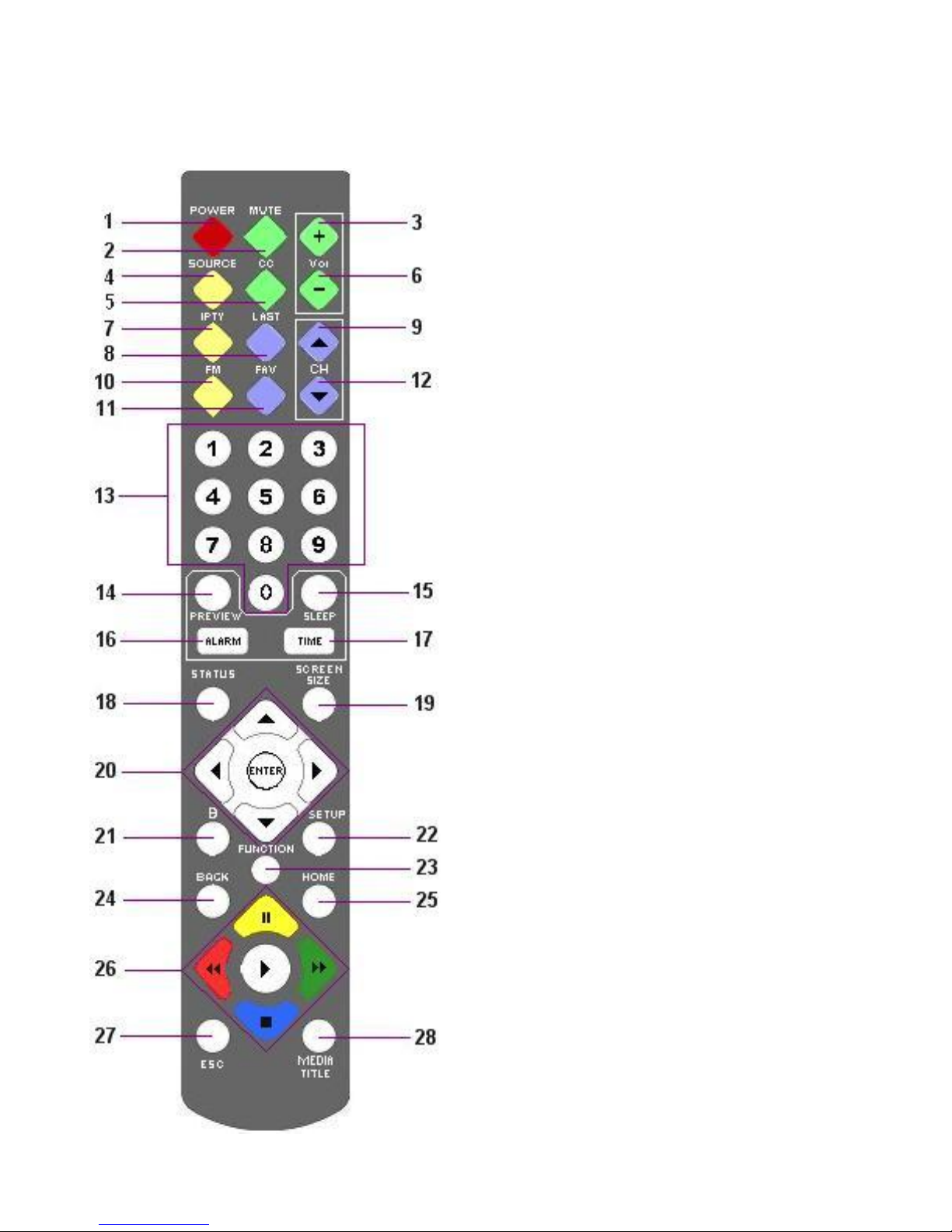
IR Remote Control
1. POWER POWER ON/OFF, IR BAND SELECT
2. MUTE MUTE ON/OFF
3. VOLUME UP INCREASES SOUND LEVEL
4. SOURCE SELECT INPUT SOURCE
5. CC CLOSED CAPTION MODE
6. VOLUME DOWN DECREASES SOUND LEVEL
7. IPTV ANDROID HOME SCREEN
8. LAST GOTO LAST CHANNEL/ SOURCE
9. CHANNEL UP UP ONE CHANNEL
10. FM SELECTS FM MODE
11. FAVORITES FAVORITES FUNCTION
12. CHANNEL DOWN DOWN ONE CHANNEL
13. NUMBER BUTTONS DIRECT ACCESS TO CHANNELS
14. PREVIEW PREVIEW MODE (PIP)
15. SLEEP SLEEP TIMER
16. ALARM SET ALARM(S)
17. TIME DISPLAY DATE AND TIME
18. STATUS DISPLAY TV CHANNEL STATUS
19. SCREEN SIZE SETS SCREEN SIZE (ZOOM)
20. NAVIGATION UP, DOWN, RIGHT AND LEFT
NAVIGATION BUTTONS
21. BANK CHANGE BANKS
22. SETUP ENTER SETUP MENU
23. FUNCTION ENTER FUNCTION/SETUP CODES
24. “.” and BACK ANDROID BACK
DIGITAL TV “.” BUTTON
25. HOME RETURN TO MAIN IPTV MENU
26. MEDIA CONTROL CONTROLS MEDIA PLAYBACK
27. ESC ESCAPE
28. MEDIA TITLE DISPLAYS INFORMATION ABOUT
CURRENT SELECTION
-------------------------------------------------------------------------------------GEN III OPERATIONS MANUAL
HealthCare Information, LLC
9
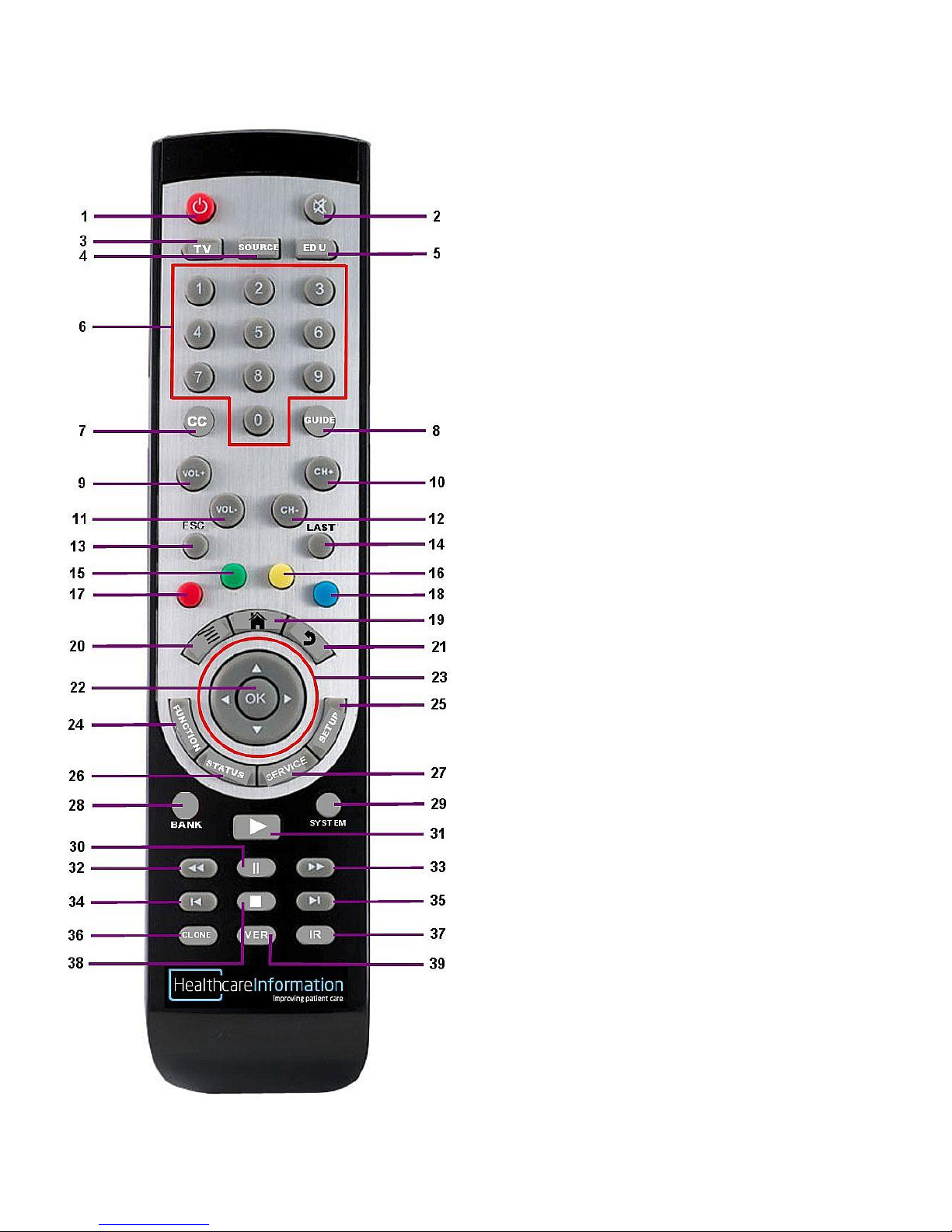
1. POWER TURNS SET ON/OFF
2. MUTE MUTE ON/OFF
3. TV GOTO TV
4. SOURCE SELECTS INPUT SOURCE
5. EDU OPENS EDU FOLDER
6. NUMBER BUTTONS DIRECT ACCESS TO CHANNELS
7. CC CLOSED CAPTION MODE
8. GUIDE SHOW CHANNEL GUIDE
9. VOL+ INCREASE VOLUME
10. CH+ UP ONE CHANNEL
11. VOL- DECREASE VOLUME
12. CH- DOWN ONE CHANNEL
13. ESC EXCAPE
14. LAST PREVIOUS CHANNEL/SOURCE
15. GREEN APP LAUNCH GREEN APP
16. YELLOW APP LAUNCH YELLOW APP
17. RED APP LAUNCH RED APP
18. BLUE APP LAUNCH BLUE APP
19. HOME GOTO ANDROID HOME SCREEN
20. MENU ANDROID MENU
21. BACK ANDROID BACK
22. OK ENTER
23. NAVIGATION UP, DOWN, LEFT AND RIGHT
NAVAGATION
24. FUNCTION ENTER SERVICE/SETUP CODES
25. SETUP ENTER SETUP MENU
26. STATUS CURRENT CHANNEL INFORMATION
28. BANK CHANGE BANK
29. SYSTEM ENTER SETUP MENU
30. PAUSE PAUSE MEDIA/DVD
31. PLAY PLAY MEDIA/DVD
32. REWIND REWIND MEDIA/DVD
33. FAST FORWARD FAST FORWARD MEDIA/DVD
34. REWIND CHAPTER GO BACK ONE CHAPTER
35. FORWARD CHAPTER GO FORWARD ONE CHAPTER
36. CLONE LOAD TV CLONE FROM USB
37. IR CHANGE IR BAND
38. STOP STOP MEDIA/DVD
39. VER DISPLAY SOFTWARE VERSION(S)

-------------------------------------------------------------------------------------GEN III OPERATIONS MANUAL
HealthCare Information, LLC
10
LEFT SIDE INPUT PANEL 10 BUTTON KEYPAD
FRONT PANEL
22/42 INCH
26/32 INCH

-------------------------------------------------------------------------------------GEN III OPERATIONS MANUAL
HealthCare Information, LLC
11
REAR I/O PANEL
SINGLE PILLOW SPEAKER BOARD USB1/USB2 PILLOW SPEAKER BOARD

-------------------------------------------------------------------------------------GEN III OPERATIONS MANUAL
HealthCare Information, LLC
12
INSTALLATION
Before installing, carefully read the “Important Safeguards” section on page 6.
Do not plug the set in until the rest of the installation is finished.
Use only the included UL listed Hospital Grade Power Cord.
If hanging the set on a wall, make sure the wall mount used is rated to carry the weight of the set. All HCI TV’s utilize standard
VESA mounting patterns. Follow the directions that came with your mount. The available VESA patterns can be found in the
specifications section of this manual. See pages 42-46.
RM22III 18lbs
RM26III 30lbs
RM32III 39lbs
RM42III 48lbs
BASIC CONNECTIONS
Antenna or Cable
Connect the antenna or cable lead to the RF input connector on the rear jack panel.
Equipment With Composite Audio and Video Outputs
You can connect a device with composite audio/video outputs such as a DVD or VCR player to the composite input
jacks on the left side of the TV (AV2) or on the rear jack panel (AV1). Connect the video output of the device to the
yellow jack, the right audio output of the device to the white jack and the left audio output of the device to the red jack.
Change the source to AV1 or AV2 to use the device.
PC (to use TV as a monitor)
A computer can be connected to the HDMI jack on the rear jack panel.
External Speakers
Analog and digital outputs are provided to provide audio to an external amplifier.
Pillow Speaker(s)
Before connecting the pillow speaker to the TV, perform the basic setup in the GETTING STARTED section.
See pages 16 and 19.
Single Pillow Speaker Board
To connect the TV for pillow speaker control you will need a jumper with either a ¼” phone plug or a 6-Pin Amphenol
plug on the TV end. The other end should match your wall jack. See page 36.
Three button analog pillow speakers and a sip & puff devices must use the 6-Pin Amphenol jack only. A ¼” jack is
provided on the left side input panel of the 26 and 32 inch sets. This jack can be used for a single function puff device.
For Zenith, Philips and one button analog type digital pillow speakers, use either jack.
NOTE: Zenith, and Philips type pillow speakers refers to the digital code the pillow speakers send to the TV,
not the manufacturer of the pillow speaker. Visitor Station refers to the optional Visitors Station that
allows visitors to control the set without interrupting the patient. The Single Pillow Speaker Board
Ver.1 will also support RCA pillow speakers.
The ¼” jack and the 6-pin jack cannot be set for different types of pillow speakers with the Single Pillow Speaker
Board.

-------------------------------------------------------------------------------------GEN III OPERATIONS MANUAL
HealthCare Information, LLC
13
USB PILLOW SPEAKER BOARD
The Dual Pillow Speaker Board allows two different pillow speakers or one pillow speaker and a Visitor Station to be
connected to the set at the same time. You will need to set the ¼” jack and the 6-pin jack separately. You will need one
jumper with a 6-Pin Amphenol plug on one end and a second jumper with a ¼ inch jack on one end. The opposite ends
of both cables should match your wall jacks. Three button analog pillow speakers must use the 6-Pin Amphenol jack
only. A sip and puff device must be connected to the 6-pin jack of the 22 and 42 inch sets. A single function puff
device can be connected to the ¼” jack on the side input panel of the 26 and 32 inch sets.
An optional 2nd Audio Channel board is available to allow two devices to have independent audio control.
Third Party Controllers
Connect third party controllers to the RJ-12 communications port(s). Sets with single pillow speaker boards will have
one RJ-12 jack and sets with dual pillow speaker boards (optional) will have two RJ-12 ports. If you have a dual pillow
speaker board please contact your dealer to determine which jack to use for you application.
Software Updates
Mstar software can be updated via the USB ports. See page 26. TV software (M-star) is updated via the USB SW-
update port on the rear jack panel located next to the digital audio jack. See page 11. This is the only USB port that can
be use for TV software updates. This port is not available to the Android operating system. This port is also used for
TV cloning.
Android system updates are installed via the USB port next to the RJ-45 jack (Ethernet port) or the USB port located on
the left side of the TV.
TV’s with Android version 345 or higher can update the Android software via Ethernet. The set must be connected to a
network with a server running NFS. A USB flash drive must be plugged into one of the USB ports. Only one USB
flash drive can be plugged into the set during an Android system upgrade. A system administrator with HCI training is
required. Sets with older software can be updated to Android 345 or higher via USB update.
Contact you dealer for availability of updates.

-------------------------------------------------------------------------------------GEN III OPERATIONS MANUAL
HealthCare Information, LLC
14
SETUP AND OPERATION
Installing The IR Remote Control Batteries
1. Turn the IR Remote over. Press down on the arrow and slide the battery cover off the bottom.
2. Install the two included AAA batteries. The polarity is indicated on the bottom of the battery compartment. Make sure
the batteries are installed correctly.
3. Slide the battery cover back onto the remote and snap into place.
Once the installation is complete and all optional equipment is connected plug the supplied power cord into the set and then into
a standard 120VAC outlet. Turn the set on by pressing the power button on the front panel or IR controller.
GETTING STARTED
The following section will get you new TV up and running in the shortest possible time. Once you have one set setup you can
clone the setup to other sets via the USB SW-update port. You will need a USB flash drive for cloning. See page 26 for cloning
instructions.
Set Quick Setup
1. Plug set into a proper electrical outlet.
2. Connect signal source to tuner input. See pages 11 and 12.
3. Turn set on. The Setup Wizard will appear. If the Setup Wizard does not appear enter function code “15719”
4. Follow the on screen prompts and use an HCI IR remote to enter basic information.
A. Select Menu Language. Choices are English, French and Spanish. When finished press the “ENTER” button twice.
B. Select only IR BAND 1 at this time. You can change it later if necessary. When finished press the “ENTER” button
twice. Changing to IR BAND 2 will cause loss of IR control.
C. Select the time zone for your area. When finished press the “ENTER” button once.
D. Select DST (Daylight Saving Time) On or Off. When finished press the “ENTER” button once.
E. Select Time Format 12-hour or 24-hour. When finished press the “ENTER” button twice.
F. Select TV source. Select cable if your signal source if from cable. Select Air if you set is connected to an antenna.
When finished press the “ENTER” button twice.
The set will now Auto Scan for available analog and digital channels. Found channels will automatically be added to the
channel line up.
NOTE: When you reset the set by entering function code 15719 the set will be restored to the new set condition.
Set quick Setup With Clone File
If you have already set up a set you can quickly setup additional sets by creating a clone file from the first set and loading the
clone file into additional sets. See page 26 to create a clone file.
1. Plug set into a proper electrical outlet.
2. Turn set on. If the set Setup Wizard appears press the ESC button on the IR remote.
3. Insert a flash drive with the saved clone file into the USB update port. See page 11.
4. Using an IR remote press the “FUNCTION” button. A key icon will appear on upper left side of the screen.
5. Press the “0” (zero) button. Code: 00000 will appear on the upper right side of the display.
6. Enter “9999”. << Menu Unlock>> will appear at the top of the screen.
7. Press the “FUNCTION” button.
8. Press the down arrow button to select Load From USB.

-------------------------------------------------------------------------------------GEN III OPERATIONS MANUAL
HealthCare Information, LLC
15
9. Press the right arrow button and then press the “ENTER” button to load the clone file. The set will load the clone file and then
turn off.
10. Remove the flash drive and turn the set on. The set will now have the channel line up and settings as the first set.
NOTE: The set you are cloning from and the set you are cloning to must have the same version of Mstar software. To check
the software version numbers enter function code “1111” and press the “ENTER” button.
Function Codes
Setup features are accessed using function codes. You will need an IR remote control to enter function codes. To enter a function code
using an IR remote control, press the “FUNCTION” button. A key ICON will appear on the upper left side of the screen. Press the “0”
button. CODE: 00000 will appear on upper the right side or the screen. Enter the desired function code. The numbers will appear as
you enter them. The following codes are available.
CODE
9999
1111 “ENTER”
15719
15729
15739
FUNCTION
ACCESS TV SETUP MENU (factory mode)
DISPLAY SOFTWARE VERSION
RESET
RESET AND LOAD CLONE FILE
RESET TO CATV LINEUP 1-1
To access the setup menu enter function code 9999. MENU UNLOCK will appear briefly at the top of the screen. Press the “SETUP”
button to access the TV setup menu. Press the “FUNCTION” to enter the advanced TV setup menu. When you are done making
changes press the “SETUP” button until the OSD menu window closes.
Note: To use code 15729 you must have a USB flash drive with a valid clone file on it plugged into the Mstar update port.
Channel Scan
You will need to run an auto scan for the set to find all of your analog and digital channels. If you used the Setup Wizard to scan
channel skip this section.
1. Enter the setup menu. (FUNCTION –0 –9999 –SETUP)
2. Use the left right arrow buttons to select the Channel menu.
3. Press the down arrow button. Use the left/right arrow buttons to select your signal source.
Select AIR if your set is connected to an off air antenna.
Select CABLE if your set is connected to a cable distribution system. This is the most
common setting.
4. Press the down arrow button to select Auto Scan then press the right arrow button.
5. Use the up/down arrow buttons to select the type of scan to perform.
Scan all channels Scans all RF channels for both analog and digital channels. Select this if you are not sure what
type of channels are available.
Digital channel only Scans all RF channels for digital channels only. Analog channels are skipped. Use this scan for
set connected to an off air antennal.
Analog channel only Scans all RF channels for analog channels only. Digital channels will be skipped. If you are sure
there are no viewable digital channels available you can select this scan to speed up the scanning
process.
NOTE: All digital sets can only show digital cable channels broadcast in Clear QAM. Please contact your cable company
for a list of Clear QAM channels available to you.
6. Press the ESC button once the channel scan is complete to clear the OSD.
7. Once the scan is completed continue with Pillow Speaker Setup.

HealthCare Information, LLC
16
Pillow Speaker Setup
Access the TV setup menu. (Function-0-9999-SETUP) Use the right arrow button to select the “Audio” setup menu. Press the
down arrow button to select “Pillow SPK1 Mode” for ¼” jack or “Pillow SKP2 Mode”for 6-pin jack. Use the left and right
arrow keys to select the type of pillow speaker you wish to use. For digital pillow speakers, the pillow speaker type is
determined by the code it outputs. See page 19. Selections are:
ZENITH –RCA –PHILIPS –ZEN-5V –VISITOR STATION –R5 INTERACTV –
G4 INTERACTV –G4R5 STANDARD –1 KEY –3 KEY
Once the proper pillow speaker is selected you can plug the pillow speaker(s) into the set. If the 6-pin jack is not being used
Pillow SPK2 Mode should be set to none.
Setting the Date and Time
You must set the date and time or turn Auto Sync on for the alarms, Power ON/Off Time and Android Auto Reset to function
correctly.
Enter the setup menu. (FUNCTION –0 –9999 –SETUP. Use the right arrow button to select the Time menu. Use the down
arrow to select Auto Sync. If Auto Sync is on the time and date will be set automatically when a digital channel is tuned to. If
Auto Sync is set to Off you will need to set the time and date manually. You can not manually set the date and time if Auto Sync
is On.
To manually set the date and time use the “Down Arrow” button to select “Clock”. Press the “Right Arrow” button. Use
the left/right arrow buttons to select the parameter to change. Use the up/down arrow buttons to make changes. When
finished press the “Right” arrow button until the OK button is selected. Press the “ENTER” button.
NOTE: For Auto Sync to function there must be at least one viewable digital channel available. The time will be set when a
digital channel is first tuned to and updated every time a digital channel is tuned to. For the correct time to be set the
Time Zone and DST must be properly set.
Time Zone and DST can be set during the initial setup or in the OSD TIME menu. See Page 19.

HealthCare Information, LLC
17
BASIC TV SETUP MENUS
Enter the TV setup menu. (Function –0 –9999 –SETUP). Use the left/right/up/down arrow buttons to make and change
selections. Press the “SETUP” button to go back.
Picture Picture Settings
Picture Mode Preset settings for Contrast, Brightness, Sharpness, Tint and Color. Selections are:
Standard –Dynamic –Soft –Personal
NOTE: Picture Mode must be set to Personal to manually adjust Contrast, Brightness, Sharpness, Tint and
Color.
Contrast Adjusts the contrast. Contrast is the difference between light and dark areas of the picture.
Brightness Adjusts overall brightness of the picture.
Sharpness Adjusts sharpness of the picture. A lower setting may improve the quality of poor or low quality channels.
Tint Adjusts the tint or Hue of the picture. Usually set to make flesh tones look correct.
Color Adjusts the color level or color saturation of the picture.
Color Mode Adjusts the individual Red, Green and Blue colors.
Color Mode Preset setting for the Red, Green and Blue colors. Selections are:
Normal –Warm –Cold –Personal
NOTE: Color mode must be set to personal to adjust the individual Red, Green and Blue colors.
R Adjusts red color level. Adjusts 0-255
G Adjusts green color level. Adjusts 0-255
B Adjust blue color level. Adjusts 0-255
NOTE: Changing the R, G or B settings will affect the Color and Tint
Zoom Mode Changes the screen size. Selections are:
Normal –Movie Scale –Zoom In –4:3
Normal Picture is automatically sized to fit the screen.
Movie Scale Used for viewing movies that have not been resized to fit a TV screen.
Zoom In Enlarges the picture. Edges of the picture may be lost.
4:3 Used to view older shows and movies broadcast in 4:3 ratio without enlarging. There will be
a black area on each side of the screen.
Noise Reduction Improves video quality of low quality video. Settings are:
Off –Weak –Middle –Strong
NOTE: Set to the lowest setting that gives good picture improvement. Setting to high may decrease the
quality of a good quality picture.

HealthCare Information, LLC
18
Audio Audio Settings.
Sound Mode Preset sound settings. Selections are:
Standard –Music –Movie –Sports –Personal
NOTE: Sound Mode must be set to Personal to adjust the Bass Treble and Balance manually.
Pillow SPK Settings for maximum and minimum volume levels, and power on volume.
Advance
PS ¼ Inch Maximum volume setting for a pillow speaker plugged in to the ¼ inch jack.
Max Vol
PS 6 Pin Dual pillow speaker board only. Maximum volume setting for a pillow speaker plugged in to
MAX Vol the 6-pin jack.
NOTE: When using a single pillow speaker board the PS ¼ Inch Max Vol. applies to both the ¼ inch jack and the
six pin jack.
Television Maximum volume setting for the television.
Max VOL
Television Minimum volume setting for the television.
Min VOL
Power ON Volume level the set will be set to when turned on. Set to “0” to use the volume setting
Vol. of the set when it was turned off.
Back Light Not used.
Bass Sets low frequency audio level.
Treble Sets high frequency audio level.
Balance Sets balance level between left and right speakers.
MTS Multichannel Television Sound settings. Selections are:
Stereo –SAP –Mono
Stereo Standard stereo sound.
SAP Second audio program. Usually a different language.
Mono Standard mono audio. May improve sound quality on weak analog signals.
Speaker Mode Sets which speaker(s) are active. Selections are:
Off - TV Only - Pillow Speaker Only - Both
Off No sound from any speakers.
TV Only Sound only from TV speaker(s).
Pillow Speaker Only Sound only from pillow speaker
Both Sound from pillow speaker and TV Speaker(s).
Pillow SPK1 Sets type of pillow speaker for single pillow speaker board. When using the standard single pillow
Mode this setting is for both the ¼” jack and the 6-pin jack. When using a dual pillow speaker board this setting is for the
¼” jack only. Selections are:
ZENITH –RCA –PHILIPS –ZEN-5V –VISITOR ST –R5 INTERACTV –
G4 INTERACTV –G4R5 STANDARD –1 KEY –3 KEY
Pillow SPK2 Sets type of pillow speaker used with the 6-pin pillow speaker jack. Settings are the same as Pillow
Mode SPK1 Mode except for “None selection. Set to “None” if no pillow speaker is plugged in to the 6-pin jack.

HealthCare Information, LLC
19
Time Clock and timer functions.
Sleep Timer Amount of time before the set turns off automatically. Selections are:
Off –5 Min –10-Min –15 Min –30 Min –45 Min –
60 Min –90 Min –120 Min –180 Min –240 Min
Time Zone Sets local time zone. This must be set correctly for Auto Sync to function correctly.
Selections are:
Atlantic - Eastern –Central –Mountain –Pacific –Alaska –Hawaii
DST Daylight Savings Time. When on and Auto Sync is on clock is set forward 1 hour during DST.
Time FormatSets how time and date is displayed. Selections are:
12-hour –24 hour
Auto Sync When On set will automatically set the date and time when tuned to a digital channel. You must have Time
Zone and DST set correctly for the correct time to be set.
Clock Set current date and time. Date and time can not be manually set if Auto Sync is set to On.
To manually set date and time:
1. Make sure Auto Sync is set to off.
2. Select “Clock” press the right arrow button.
3. Use the left/right arrow buttons to select the setting you wish to change. Use the up/down arrow buttons to
change the selected settings
4. When finished select the “OK” button and press “ENTER”. Or select the “CANCEL” button to exit
without keeping any changes.
Power On/Off Set the hours of operation of the set. Set can be operated normally between On time setting and Off
Time time setting. Time setting is in 24 hour format.
To set the ON/Off time select Power ON/Off Time under the time menu and press the right arrow button.
1. Use the up/down arrow keys to set the Power ON Time hour.
2. Press the right arrow button. Set the Power ON Time minutes.
3. Press the right arrow button. Set the Power Off time hour.
4. Press the right arrow button. Set the Power Off time minutes.
5. Press the right arrow button and the press “ENTER” to save and exit.
To cancel without saving press the right arrow button until CANCEL is selected and press the “ENTER” button. You can
use the left arrow button to return to a previous selection. To disable Power ON/Off Time set the Power ON Time and
Power Off Time to 00:00.

HealthCare Information, LLC
20
Option
Menu Language Sets the language the menus are displayed in. Selections are:
English –FranCais –Espanol
FranCais French
Espanol Spanish
Transparent Sets menu transparency. Selections are:
0% - 25% - 50% - 75% - 100%
0% is solid menu. 100% is the most transparent setting. Menu will still be visible at 100% setting.
OSD Time Out Sets how long the OSD menu will stays open. Selections are:
Off –5 Sec. –15 Sec. –30 Sec. –45 Sec. –60 Sec.
Set to off to keep the menu from timing out. When set to off OSD Time Out will reset to 30 Sec. when set
is turned off.
Close Caption Closed captioning settings.
CC Mode Sets current CC mode. This setting can also be changed using the CC button. Selections are:
CC Off –CC On –CC on Mute
CC Off Closed captions are not displayed.
CC On Closed captions are displayed.
CC on Mute Closed captions are displayed when audio is muted.
Basic Selection Sets which closed caption service is displayed when CC is on. Selections are:
Off –CC1 –CC2 –CC3 –CC4 –Text1 –Text2 –Text3 –Text4
Off Closed captions will not be displayed even if CC Mode is set to On.
CC1-4 Standard closed captions.
Text1-4 Standard text services.
NOTE: Not all stations and programs are broadcast with closed captions. Not all programs with closed
caption and text services will use all available services. Text service is similar to closed captions
except the text area is a box on the screen. If a text service is selected and there is no text to
display an empty box will show on the screen.
Advanced Selects which closed caption service to use when tuned to a digital channel.
Selection Selections are:
Off - Service1 –Service2 –Service3 –Service4 –Service5 –Service6
NOTE: Not all digital stations and programs will have closed caption service. If Advanced Selection is
set to Off no closed captions will be displayed even if CC Mode is set to On.
Option Settings for font style, size, color and opacity.
Mode Sets closed caption display to use default settings or custom settings.
Default Displayed as broadcast
Custom Overrides broadcast fonts and uses custom font styles.
Mode must be set to Custom to use your own font preferences. A sample CC display in the upper left
corner of the display will show a sample of the selections being made. Custom styles are listed on the
following page. Default setting will display the style as broadcast.
User settable styles are
Style, Size, Edge Style, Edge Color, Foreground Color, Background Color, Foreground Opacity and
Background Opacity.
NOTE: Be careful when using custom font settings. For example if you set the FG Color and BG Color
to the same color you will not be able to see the text.
This manual suits for next models
3
Table of contents
Other HealthCare Information LCD TV manuals


