3
Hearth & Home Technologies • Gas Conversion Instructions for Courtyard • 4608-904 Rev. C • 01/2020
Converting Main Burner & Pilot Orice
NOTE: Remove burner assembly from the rebox to
complete main burner and pilot orice conversion.
1. With the cover assembly removed locate the single
(1) screw securing the burner tube in place on the
left side and remove. Figure XX
2. Lift the burner tube up from the left end allowing the
air-shutter to pivot at the bulkhead. Lift until the tube
clears all the tube support brackets and pull straight
out.
3. Replace the orice located on the end of the bulk-
head with the supplied #45 orice.
4. Open the air-shutter, located at the end of the burner
tube, to fully open by loosening the screw holding
the shutter housing in place. Rotate to fully open and
retighten. See the air-shutter settings listed accord-
ing to the table 1 below.
5. Set the burner tube aside and continue on with the
conversion process by locating the pilot assembly.
6. Remove (2) screws securing pilot to the burner as-
sembly.
7. Carefully pull pilot assembly through the opening of
the burner assembly until the ttings behind the base
place are easily accessible.
8. Grasp pilot rmly and loosen the pilot tube tting.
Remove the existing pilot orice and replace it with
the pilot orice included in the kit. Ensure the pilot
orice is appropriate for the type of gas to which you
are converting the appliance. See Figure 4.
Shock or burn risk.
• Disconnect green wire from gas valve.
Failure to disconnect green wire could result in
severe burns.
WARNING
Gas Type Burner
Orice
Pilot
Orice
Burner
Air
Shutter
NG #27 0.023 1/16”
Open
Propane #45 0.014 Fully
Open
Table 1.
9. Secure pilot assembly to burner assembly with (2)
screws.
10. Holding the left end of the burner tube up at an angle
with the air shutter at the lowest point. Slip the air
shutter over the orice and rotate the tube down over
the support brackets until coming to rest on the burn-
er attachment bracket.
11. Reinstall the single screw on the left end of the burner
tube.
12. Disconnect green wire attached to the gas valve.
WARNING
Delayed Ignition Risk
• Place media according to instructions.
• Do NOT place media in area in front of pilot.
• Do NOT place media in a position that they may
fall into area in front of pilot.
• Do NOT use any media other than the media
supplied with this replace.
Fireplace will not function properly.
Delayed ignition may occur.
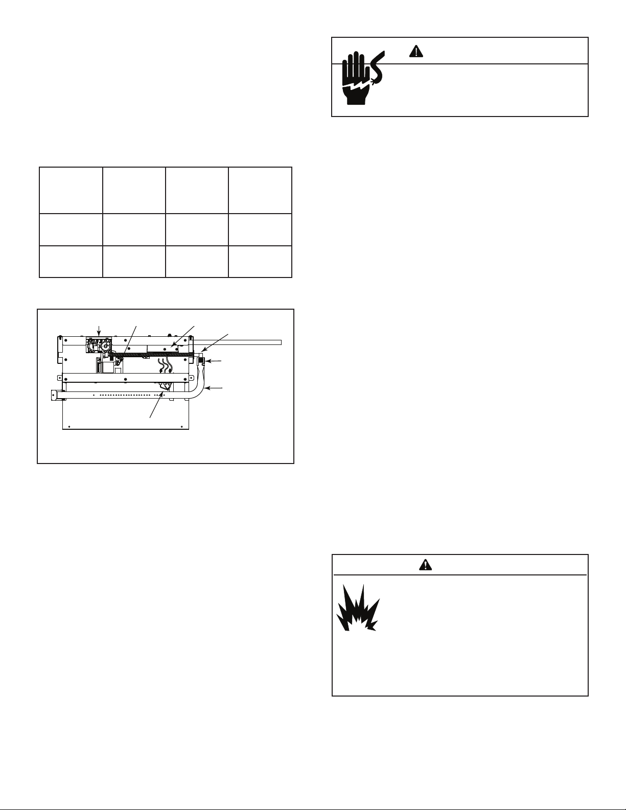
Figure 3.
Valve Control
Module
Junction
Box
Injector
Burner
Tube
Pilot
13. Turn on gas supply and electrical power to the appli-
ance.
14. Turn appliance “On” and use a commercially avail-
able, non-corrosive leak check solution to test for
leaks around the pilot tting. See Figure 4.
15. Extinguish the pilot ame by turning the appliance
“O”.
16. Reconnect green wire to the valve.
17. Turn the appliance “On” and use a commercially
available, non-corrosive leak check solution to test for
leaks around the newly installed gas valve regulator.
18. Turn the appliance “O” to extinguish pilot and main
burner ames.
19. Be sure to rinse o all leak check solution following
testing and prior to placing the appliance into opera-
tion.
20. Reinstall the cover assembly, secure using (6) screws.
21. Verify that the conversion plate has been signed and
dated. Ax the conversion plate adjacent to the rating
label.
22. Install media per the instructions included with the
media kit or in the appliance installation manual.