Hearth & Home 2767/FK26 User manual

Fan Kit #2767/FK26 - Installation Instructions
for Radiance, Stardance, Dutchwest & Oxford Gas Heaters and Deant
NC, FB & CAT-C, Dutchwest NC, Encore NC, FB & CAT-C, Wood Stoves
2003135_R19 • 10/19
MOTOR
SNAPSTAT
ON/OFF
RHEOSTAT
WHT
WHT
BLK
BLK
BLK
GRN
BLK
ST236
FK26 wiring diagram
12/99
#2767 / FK26 Fan wiring diagram.
Please read these instructions before proceeding with
installation.
Kit contents
• Fan Assembly with Rheostat and Snapstat
• Fan Mounting Bracket for RVF33
• Snapstat Mounting Bracket
• RheostatBracket(DeantNC,FB&CAT-C/EncoreNC,
FB&CAT-C)
• 1/4-20x3/4”hexheadscrews,(4)
• 1/4-20hexnuts,(2)
• 1/4”StarWashers,(2)
• #8StarWasher,(1)
• #10SheetMetalScrews,(2)
• RetainingNut(1)
• ControlKnob
• WireTie
Tools Needed
• Flat blade screwdriver
• Workgloves
• Phillips screwdriver
It is easiest to install the fan before the stove is connected
tothegassupplyline.Comparethecontentsofthefankit
withthelistaboveandFigure1toconrmthatyouhaveall
of the parts.
D
E
S
I
G
N
C
E
R
T
I
F
I
E
D
Thiskittsseveraldierentstoves;followtheproceduresfor
yourspecicstove.Matchtheseinstructionstothemodel
nameand/ornumberonthestove’sinstructionsornameplate.
Avoid any drafts that alter burner ame patterns. Do
not allow fans to blow directly into the replace.
This optional fan kit is equipped with a three-pronged
(grounding) plug for your protection against shock
hazard and should be plugged directly into a properly
grounded three-pronged receptacle. Do not cut or
remove the grounding prong from this plug.
WARNING
!
Fan Kit contents.
Rad2767 Fan Kit Parts.eps
RDV40, RNV40,
RVF33, SDV30
Snapstat Bracket
RheostatWire
Harness Assy
Fan
Assembly
RVF33 ONLY
Fan Mounting
Bracket
#8StarWasher
1/4”Star
Washer
1/4”Star
Washer
1/4-20x3/4”
HexBolts
1/4-20Hex
Nuts
#10Sheet
Metal Screws
1/4-20x3/4”
HexBolts
ConnecttoPCBoard
on RF Models Only
Snapstat
Deant/Encore
Rheostat Bracket

Fan Kit #2767/FK26 - Installation Instructions
for Radiance, Stardance, Dutchwest & Oxford Gas Heaters and Deant
NC, FB & CAT-C, Dutchwest NC, Encore NC, FB & CAT-C, Wood Stoves
2003135_R19 • 10/19
Table of Contents
Radiance
Direct Vent
RADVT................................................................................ 3
RDV40................................................................................. 3
RDVOD ............................................................................... 4
Natural Vent
RNV40................................................................................. 5
RNVOD
(Serial#’supto1456(RNVODRN),1944(RNVODRP)............... 6
(Serial#’sstartingat1457(RNVODRN),1945(RNVODRP)..........7
Vent Free
RVF33 ................................................................................. 9
RUVS40 ............................................................................ 10
RUVSOD............................................................................11
Stardance
Direct Vent
SDDVT.............................................................................. 13
SDV30............................................................................... 14
SDV30R ............................................................................ 15
Natural Vent
SNV30(Drop-inBurner).................................................... 16
SNV30Models3074,3075
(Serial#’sup5250(SNV30RN),5483(SNV30RP) .................... 17
(Serial#’sstartingat5251(SNV30RN),5484(SNV30RP)......... 18
Dutchwest Direct Vent/Natural Vent................................. 20
Oxford Direct Vent/Natural Vent ....................................... 20
Dutchwest Natural Vent..................................................... 20
Deant NC/FB/CAT-C ......................................................... 22
Dutchwest NC .................................................................... 22
Encore NC/FB/CAT-C ......................................................... 22

32003135
Radiance Direct Vent - RADVT
1.Removetherearshroudpanel(Figure6)andfastenthe
blowerassembly totherebox backwiththetwobolts
provided.(Figure7)
2.Attachthesnapstatassemblytothesnapstatbracketwith
two sheet metal screws. Attach the snapstat bracket to
thesideshield.(Figure7)
3.Therheostatcontrolswitchattachestotheleftsideofthe
valvebracketatthefrontofthestove.(Figure1)
Figure 1-Attachthefanrheostat.
ST347a
JUV
FK28
rheostat install
9/21/00
Rheostat
Retaining nut
RheostatKnob
Rheostat
3. Secure the fan assembly to the bottom plate with two
(2)1/4-20x3/4”hexheadscrewsandone(1)1/4”star
washer.(Figure3)
Figure 3-Attachfanassembly.
ST149
rdv attach fan assy
10/99
Side Shield
Snapstat
1/4-20x3/4”
HexBolts
Kt247
RVF remove rear shroud
C
A
B
Figure 2 -Removerearshroudandswitchbox.
• Removeretainingnutfromshaftofrheostat.(ifpre-
installed)
• Insert the rheostat through the hole in the back of the
leftsideofthevalvebracket,aligningthelocatorpin
with the smaller hole in that bracket.
• Threadtheretainingnutontotheshaftoftherheostat,
tightening with a wrench. Do not overtighten.
• Attach the control knob to the rheostat shaft.
• Use the wire tie to secure the fan and rheostat wire
harnesses together.
RDV40
1. Remove the Rear Shroud. Use work gloves to protect
againstsharpedges.Loosenthetwo(2)screwsoneach
side just enough to disengage the shroud panel from the
sidesofthestove.(Figure2)
2.Removetheswitchbox(Figure2)
• Remove the sheet metal screw from the left side (as
youfacetherearofthestove)oftheswitchbox.
• Remove the phillips screw and washer from the right
sideoftheswitchbox.
• Removetheholeplugfromtheswitchbox.
ST150
rdv attach snapstat
10/99
Heat Shield
Use Lower Hole
Figure 4-Attachsnapstatbracket.
• Attach the snapstat bracket to one of the side heat
shields. (Figure 4) Choose the side from which the
snapstatwireharnessexitsthefanmotorhousing.It
maybeeasiesttorsttemporarilyremovetheshield
from the side of the stove before attaching the bracket.
5.Install the Rheostat into the switch box. Feed the fan
rheostat wire harness through the cut out in the rear
shroud. Insert the rheostat control shaft through the switch
boxhole whilealigningthelocatorpinwiththesmaller
hole. Install the retaining nut and knob onto the control
shaft.(Figure5)
6.Reinstall the Switch box on the rear shroud using the
original screw(s). Be sure the wire harness runs down
the inside face of the shroud panel.
7.Donotreinstalltherearshrouduntilthestarterventpipe
has been installed on the stove. Refer to Homeowners
Manual for details.
4. Attachsnapstattothesnapstatbracketusingtwo(2)sheet
metalscrewsandone(1)#8starwasherasshownon
Page 1.

42003135
T'STAT
OFF
ON
ST151
rdv install rheostat
10/99
RheostatKnob
RetainingNut
Rheostat
Figure 5-Installrheostatintoswitchbox.
RDVOD
1. Removethe rearshroudpanel(Figure6) andfasten
theblowerassemblytothereboxbackwiththetwo
(2)boltsprovided.(Figure7)
NOTE: Steps2and3donotapplywhentheRFvalveis
used.Afterattachingblowerassemblytotherebox,run
the spliced female leads to the front of the stove and attach
tobackofHoneywellRFComfortvalve.(Figure8)
ST147
RDV40 remove rear shroud
10/99
Figure 6 - Remove rear shroud panel.
ST149
rdv attach fan assy
10/99
Side Shield
Snapstat
1/4-20x3/4”
HexBolts
Figure 7-Attachfanassembly.
2. Attachthesnapstatassemblytothesnapstatbracketwith
two(2)sheetmetalscrews.Attachthesnapstatbracket
tothesideshield.(Figure7)
3. Therheostatcontrolswitchattachestotheleftsideofthe
valvebracketatthefrontofthestove.(Figure9)
• Removeretainingnutfromshaftofrheostat.(ifpre-
installed)
ST347a
JUV
FK28
rheostat install
9/21/00
Rheostat
Retaining nut
RheostatKnob
Rheostat
Figure 9-Attachfanrheostat.
FAN
Antenna
Red
White
Red
White
FP1038
comfort valve
wiring diagram
3/24/00 djt
WhiteDots
Valve
(Bottom View)
Blower
Pilot Assembly
Figure 8-FK26iswiredtobackofComfortValve.
• Insert the rheostat through the hole in the back of the
leftsideofthevalvebracket,aligningthelocatorpin
with the smaller hole in that bracket.
• Threadtheretainingnutontotheshaftoftherheostat,
tightening with a wrench. Do not overtighten.
• Attach the control knob to the rheostat shaft.
• Use the wire tie to secure the fan and rheostat wire
harnesses together.

52003135
ST369
RNV
rheostat &
snapstat assy
5/19/00 djt
Switchbox
Rheostat
Assy.
StarWasher
Snapstat
Housing
Snapstat
Bracket
On/OSwitch
Cord
Rheostat
Cord Screws
1/4-
20x1/2”
HexBolts
Star
Washer
Slot
Fan Shield
Edge“A”
HexNuts
Figure 11-Attach fan,snapstatassembly andsnapstatbracket
to rear skirt.
Radiance Natural Vent - RNV40
1. Remove the rear skirt. Use work gloves to protect your
hands.Removesix (6) sheetmetalscrewsaroundthe
edgeofthedrafthoodopening.(‘A’,Figure10)Remove
the rear skirt cover plate: three (3) screws hold it on.
(‘B’,Figure14)Removeone(1)sheetmetalscrewholding
theswitchboxtotherearskirt.LoosenthePhillipshead
boltoneachsideoftherearskirt.(‘C’,Figure10)Carefully
pulltheskirtassemblystraightback;awiretieholdstwo
(2)wiringharnessestotherearskirt.Settheskirtdown
carefully,eitherremovethewiretie,orlettheharnesses
holdtheskirtedgeotheoor.
2.Position the fan assembly. Place the fan behind the
rear skirt as shown in Figure 11. Pass the fan rheostat
assembly and snapstat assembly up through the slot in
the horizontal top surface of the fan shield attached to the
inside of the skirt.
3. Attach the snapstat housing to the snapstat bracket with
two(2)sheetmetalscrewsandone(1)#8starwasher.
(Figure11)
ST370
attach
rheostat knob
5/19/00 djt
Rheostat
Retaining nut
Sheet Metal Screw
Knob
SwitchBox
Figure 12-Attachrheostatretainingnutandknob.Attachswitch
boxtorearskirtwithsheetmetalscrew.
6.Bringtherheostatcordtotheinsideofthestove;passthe
cordthroughtheslotattheedgeoftherearskirt,where
theon/oswitchpassesthrough.Lifttherearskirtinto
roughposition;makesurethefanandon/oswitchwires
are not trapped between the skirt and inner draft hood
assembly.Theon/oswitchandfanrheostatshouldhang
looselyoutsidethe edgeoftheskirt.Theedges ofthe
rear skirt go outside the rear vertical edges of the stove
sides.Thereisaropegasketaroundthelargeopeningin
therearskirt,makesurethisstaysinplace.Installthesix
(6)sheetmetalscrewsaroundtheperimeterofthelarge
openingintherearskirt.(‘A’,Figure13)
7.Tightenthree(3)oftheboltsholdingtherearskirttothe
stovebody;leavetheoneattheswitchboxloose.Pop
out the round chrome plug in the switch box. Remove
the rheostat knob and collar from the rheostat assembly.
Pass the rheostat stem through the hole in the switch
box;alignthelocatorpinwiththesmallerhole.Installthe
retainingnutfromtheoutsideofthehousing,andsnugit
upagainsttheswitchbox.Slidetherheostatknobonto
thestem.(Figure12)
4.Attachthesnapstatbracket,withthesnapstatassembly
mountedtoit,tothetopsurfaceofthefanshield,witha
sheetmetalscrew.Thereisapre-drilledholeintheshield
forthis.Theverticalpartofthesnapstatbracketshould
beabout3/16”backfromedge“A”inFigure11.
5.Attachthefanassemblytotherearskirtwithtwo(2)1/4
-20x3/4”hexbolts,two(2)1/4-20nutsandone(1)1/4”
starwasher.(Figure11)
Figure 10-RemoverearskirtcoverplateandrearskirtfromRNV40.
ST676
Switch Housing
5/00
Draft Hood Opening
Switchbox
C
A
B
C
RearSkirtCoverPlate
in Shipping Position

62003135
ST372
Attach rear
skirt cover
5/19/00 djt
B
DA
C
D
RearSkirtCover
Plate Reinstalled
Figure 13-Replacerearskirt,coverplateandswitchbox.
RNVOD
Theseinstructionsareforstoveswithserialnumbersupto
#1456(RNVODRN),#1943(RNVODRP).
1. Removetherearshroud.(Figure18)Useworkglovesto
protect your hands. Remove the rear shroud cover plate.
Removethesix(6)sheetmetalscrews(‘A’,Figure14)
surrounding the draft hood opening. Remove the shroud
and set aside.
ST369
RNV
rheostat &
snapstat assy
5/19/00 djt
1/4-20x
1/2”Hex
Bolts
Star
Washer
Slot
Fan Shield
Edge ‘A’
HexNuts
Snapstat
Bracket
Snapstat
Housing
Figure 15-Positionthefanbehindrearshroud.
Figure 14-Removerearshroudcoverplateandrearshroud.
ST363
Switch Housing
5/00
A
RearShroudCover
Plate in Shipping
Position
Rear Shroud
8. Fastentheswitchboxtotherearskirtwithasheetmetal
screwasshowninFigure12.TightenthePhillipsbolt
holdingtheswitchboxtotherearskirtandthestove.
9. Replacetherearskirtcoverplatewiththree(3)sheet
metalscrewsasshownat“C”,Figure12.Thetopedge
of the cover plate goes inside the rear skirt. Replace
asheetmetalscrewateachsideofthefanassembly,
holdingtherearskirttotheinnerfanshield.(‘D’,Figure
13)
10. Plug the fan cord into a standard grounded 110 volt
household outlet.
3. Therheostatcontrolswitchattachestotheleftsideofthe
valvebracketatthefrontofthestove.(Figure16)
• Removeretainingnutfromshaftofrheostat.(ifpre-
installed)
• Insert the rheostat through the hole in the back of the
leftsideofthevalvebracket,aligningthelocatorpin
with the smaller hole in that bracket.
• Threadtheretainingnutontotheshaftoftherheostat,
tightening with a wrench. Do not overtighten.
• Attach the control knob to the rheostat shaft.
• Use the wire tie to secure the fan and rheostat wire
harnesses together.
2. Positionthefanbehindtherearshroud.(Figure15)Pass
the fan rheostat assembly and snapstat assembly beneath
the stove toward the front.
ST347a
JUV
FK28
rheostat install
9/21/00
Rheostat
Rheostat
Retaining nut
RheostatKnob
Figure 16-Attachthefanrheostat.

72003135
Figure 17 - Attach rear shroud cover plate to the rear shroud.
ST372
Attach rear
skirt cover
5/19/00 djt
A
Rear Shroud
CoverPlate
A
RNVOD
Theseinstructionsareforstoveswithserialnumbersstarting
at#1457(RNVODRN),#1944(RNVODRP).
1.Loosenthefour(4)phillipsheadscrewswhichsecurethe
rearshroudtothestovesides.(Figure18)
ST713fan remove shroud
radiance
11/99
Rear Shroud
Assembly
Figure 18-Removerearshroud.
4. Attachthesnapstathousingtothesnapstatbracketwith
two(2)sheetmetalscrewsandone(1)#8starwasher.
(Figure15)
5. Attachthesnapstatbracket,withthesnapstatassembly
attached,tothehorizontalsurfaceontheinsideoftherear
shroud.Useasheetmetalscrew.Therearepre-drilled
holesateachcornerofthepanelforthis.Theverticalpart
ofthesnapstatbracketshouldbe3/16”backfromEdge‘A’.
(Figure15)
6. Attachthefanassemblytotherearshroudusingtwo(2)
1/4-20x1/2”hexheadbolts,two(2)1/4”-20nutsandone
(1)1/4”starwasher.(Figure15)
7. Reattachthestove’srearshroud.
8. Reattach the rear shroud cover plate by fastening it to
therearshroudasshowninFigure17.Thetopedgeof
the cover plate goes inside the rear shroud. Reinstall and
tightenthe six(6)sheet metalscrewsaroundthedraft
hoodopening.(‘A’,Figure17)Usetwo(2)screwsfrom
thefankittofastentherearshroudtothefanshield.(‘A’,
Figure17)
9. Plug the fan cord into a standard grounded 110 volt
household outlet.
ST669
RUVSOD
attach fan to bracket
7/01
Snaptstat
Wire Rheostat
Wire
Fan
Bracket
Finger Guard
Figure 19-Attachthefanassemblytothefanbracket.
5.Connectsnapstatleads.Disconnectthesnapstatmodule
fromthe leadsinsidethe snapstatbracket.(Figure20)
Bend open the snapstat bracket. Use needle nose pliers
to remove the black plastic grommet from the bracket.
Discard the bracket. Insert the grommet and wires into the
large hole at the bottom right corner of the inner shroud.
Feed the snapstat wire leads through the grommet into
thestoveinterior.Connectthetwo(2)wirestothetwo(2)
snapstatextensionleadsattachedtotheinnershroudor,
onsomemodels,betweentheinnerandoutershroud.
ST640
RUVSOD
snapstat
7/01
Snapstat Bracket
Snapstat Module
Pinch Grommet
to Remove
Figure 20-Removethesnapstatandgrommetformthebracket
and insert the grommet into the inner shroud.
2.Carefullypulltheshroudassemblyawayfromtherearof
the stove.
3.Withtherearshroudassemblyintheuprightposition,set
the bottom of the shroud on a padded surface to prevent
scratching the surface. Unfasten the four phillips head
screws which attach the outer shroud to the inner duct
assembly.
4.Attachthefanassemblytothefanbracketprovidedinthe
nishbagusingthe#10sheetmetalscrewsprovidedin
fankit.Donotremovengerguardscrews.(Figure19)

82003135
ST347a
JUV
FK28
rheostat install
9/21/00
RetainingNut
ControlKnob
Figure 23-Attachrheostattoleftsideofvalve.
ST194
attach fan to shroud
11/99
SlotOuter
Shroud
Slot
Inner Shroud
Figure 21-Positionthefantoengagetheinnershroudwiththefan
bracket slots and secure with sheet metal screws.
ST195
attach snapstat
11/99
Left Air Duct Snapstat
Figure 22-Installthesnapstatandconnecttotheextensionwire
terminals.Viewiswithtopremoved,however,accessisavailable
through the rear when installing fan before gas line connection.
13.Plugthepowercordintoastandardgrounded110volt
household outlet. If the fan control knob is not turned
to the OFF position, the fan will turn on when the
temperature at the snapstat reaches approximately
109°F.
7. Routetherheostatwireassemblytotherightbetweenthe
inner and outer shroud. Run the wire through the slots at
the bottom right corner of the inner shroud. Some models
havetheextensionwireassemblyattachedtotheinner
shroud.
8. Refasten the outer shroud to the inner duct assembly.
9.Installthesnapstatbylooseningthefrontscrewonthe
inner side of the duct. (Figure 22) Slide the snapstat
undertheheadofthescrewandtighten.Connectthe
leads to the snapstat. Make sure the snapstat assembly
is mounted straight front to back.
6.Positionthefanassemblysotheductsslidebetweenthe
innerandoutershroud.Theinnershroudshouldengage
withthetwo(2)slotsintheendsofthebracketsothat
bracketandshroudareinterlocked.(Figure21)Secure
thebracketwiththefour(4)sheetmetalscrewsprovided
inthenishbag.
10. Slideshroudassemblyoverthesidesandfastenthefour
(4)screwsloosenedearlier.
11. Therheostatcontrolswitchattachestotheleftsideof
thevalvebracketatthefrontofthestove.(Figure23)
• Removeretainingnutfromshaftofrheostat.(ifpre-
installed)
• Insert the rheostat through the hole in the back of the
leftsideofthevalvebracket,aligningthelocatorpin
with the smaller hole in that bracket.
• Threadtheretainingnutontotheshaftoftherheostat,
tightening with a wrench. Do not overtighten.
• Attach the control knob to the rheostat shaft.
• Use the wire tie to secure the fan and rheostat wire
harnesses together.

92003135
RVF33
1. Remove the rear shroud. Use work gloves to protect
againstsharpedges.Loosenthetwo(2)screwsoneach
side just enough to disengage the shroud panel from the
sidesofthestove.(Figure24)
2. Removetheswitchbox.(Figure24)
• Remove the sheet metal screw and washer from the
leftside(asyoufacetherearofthestove)oftheswitch
box.
• Remove the phillips screw and washer from the right
sideoftheswitchbox.
• Removetheholeplugfromtheswitchbox.
Kt247
RVF remove rear shroud
C
A
B
Figure 24-Removerearshroudandswitchbox.
ST150
rdv attach snapstat
10/99
Heat Shield
Use Lower Hole
Figure 26 - Attach snapstat bracket.
T'STAT
OFF
ON
ST151
rdv install rheostat
10/99
RheostatKnob
RetainingNut
Rheostat
Figure 27-Installrheostatintoswitchbox.
6. Install the rheostat into the switch box. Feed the fan
rheostat wire harness through the cut out in the rear
shroud. Insert the rheostat control shaft through the switch
boxhole whilealigningthelocatorpinwiththesmaller
hole. Install the retaining nut and knob onto the control
shaft.(Figure26)
7. Reinstall the switch box on the rear shroud using the
original screw(s). Be sure the wire harness runs down
the inside face of the shroud panel.
8. Reinstalltherearshroudandtightenthefour(4)screws.
Figure 25-AttachfantoRVF33.
RVF33 attach blwr&snpstat
Rheostat
Snapstat
#8StarWasher
Sheet Metal
Screws
#8StarWasher
1/4-20x3/4Hex
Head Screws
5. Attachthesnapstat. (Figure 11) Use the two(2)sheet
metal screws and single #8 star washer to secure the
snapstattothebackoftherebox.
3. Install the fan mounting bracket to the blower assembly
withtwo(2)1/4-20X3/4”hexheadscrewsandoneof
the1/4”starwashers.(RefertoPage1)
4. Securethefanassemblytothebottomplatethroughthe
mountingbracketwiththeothertwo(2)1/4-20x3/4”hex
headscrewsandtheremaining1/4”starwasher.(Figure
24)

10 2003135
Radiance Unvented (RUVS40):
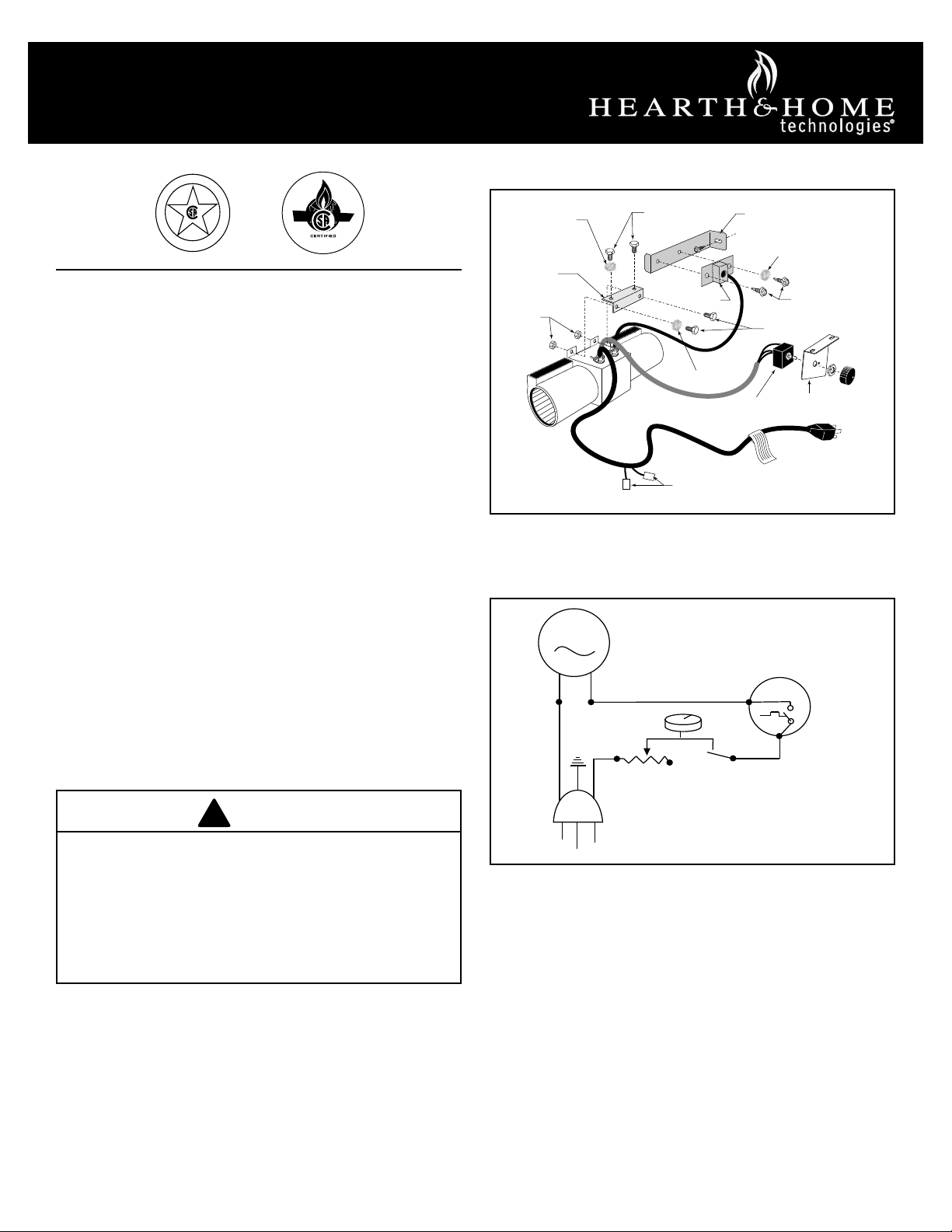
Thefankitincludesa‘snapstat’,atemperaturesensingswitch
which will be mounted to the blower duct just below the top
plateofthestove.Thesnapstatautomaticallyturnsthefan
onoroatapproximately109°F.
Thesedirectionsareorientedfacingtherearofthestove.
PositionthefanundertherearshroudasshowninFigure28.
1.Opentheleftsideofrearshroud.(Figure28)
• Removetheroundheadphillipsscrews(B)thatsecure
the shroud to the side of the stove.
• Removethesheetmetalscrew(C)thatfastens the
switchboxtotherearshroud.
• Removethetwo(2)sheetmetalscrews(D)thatsecure
theinnerandoutershroudtogether.Lettheswitchbox
and wiring hang loosely.
2. Installthecontrolswitch.(Figure28)
• Runthecontrolswitch(E)andwireupalongtheside
between the inner and outer shrouds and through the
slot at the side.
• Attachtheswitchtotheswitchboxwiththeretaining
nutandcontrolknob(F).
• Secure the switch box assembly to the rear shroud
withthesinglesheetmetalscrew(C).
3. Connectsnapstatleads.
ST190
Snapstat detail
11/99
Pinch Grommet
to Remove
Figure 29-Removesnapstatandgrommetfromthebracket.
ST192
feed snapstat
11/99
Outer Shroud Inner Shroud
Grommet
Figure 30-Insertgrommetintotheinnershroud.
ST189
fan remove shroud
radiance
11/99
H
G
A
D
B
E
F
C
AA D
A
B
Figure 28-Opentherearshroudandinstallfancontrolswitch.
5. Attach the fan assembly to the bracket supplied with
stoveinpartsbagassembly.Use#10sheetmetalscrews
providedwithfankit.Donotremovengerguardsscrews.
(Figure31)
• Position the fan assembly so the ducts slide between
theinnerandoutershroud.Theinnershroudshould
engagewiththetwo(2)slotsintheendsofthebracket
sothebracketandshroudareinterlocked.(Figure32)
Securethebracketwiththefour(4)sheetmetalscrews
previously removed.
6.Installsnapstat.Lookingthroughthestovefront,locatethe
snapstat mounting screws on the side of the left air duct
underthetopplate.Removethefrontscrew(‘A’,Figure
33),butonlyloosentherearscrew.Slipthesnapstatunder
therearscrew,replacethefrontscrew,andtightenboth.
• Detachtheextensionwirefromtheretainerclipatthe
rear.Connectthefemaleagconnectors(‘B’,Figure
33)ofthesnapstatextensiontothesnapstatmodule.
Conrm that the wires are running to the back and
away from the top of the stove.
4. Resecuretherearshroudpanels.
• Reinstallandtightenthetwo(2)sheetmetalscrews,
(‘D’,Figure28),thatsecuretheinnerandoutershrouds
together.
• Securetheuppercorneroftheshroudandswitchbox
tothesideofthestoveusinga1/4-20x1/2”round
headphillipsscrew,previouslyremoved.(‘B’,Figure
28)
• Disconnect the snapstat module (G) from the leads
insidethesnapstatbracket(H).
• Bendopenthesnapstatbracket(H).Useyourngersor
needle nose pliers to remove the black plastic grommet
fromthebracket.Discardthebracket.(Figure29)
• Insert the grommet and wires into the large hole at the
bottomrightcorneroftheinnershroud.(Figure30)
• Feed the snapstat wire leads through the grommet into
thestoveinterior.Connectthetwowirestothetwo(2)
snapstatextensionleadsattachedtotheinnershroud.

11 2003135
Figure 33-Installsnapstattoleftairduct.
ST195
attach snapstat
11/99
Left Air Duct Snapstat
A
B
RUVSOD
1. Loosenthefour(4)phillipsheadscrewswhichsecurethe
rearshroudtothestovesides.(Figure34)
2. Carefullypulltheshroudassemblyawayfromtherearof
the stove.
3. Withtherearshroudassemblyintheuprightposition,set
the bottom of the shroud on a padded surface to prevent
scratching. Unfasten the four (4) phillips head screws
which attach the outer shroud to the inner duct assembly.
NOTE: If you are installing the fan kit after the stove is
initsnallocation,followsamesteps,exceptdisengage
only the right side of the outer shroud.
ST189
fan remove shroud
radiance
11/99
Rear Shroud
Assembly
Figure 34-Loosenfour(4)phillipsscrewsholdingtherearshroud
assembly and remove. Remove four phillips screws holding rear
shroud to inner duct assembly. Remove rear shroud.
ST194
attach fan to shroud
11/99
Slot
Slot
Outer
Shroud
Inner Shroud
Figure 32-Positionthefantoengagetheinnershroudwiththefan
bracket slots and secure with sheet metal screws.
ST669
RUVSOD
attach fan to bracket
7/01
Snapstat
Wire
Rheostat
Wire
Fan
Bracket
Finger Guard
Figure 35-Attachfanassemblytofanbracket.
Figure 31-Attachfanassemblytofanbracket.
ST669
RUVSOD
attach fan to bracket
7/01
Fan Bracket
Finger Guard
Snapstat
Wire
RheostatWire
7.Plugthepower cordintoa standardgrounded110volt
household outlet.
4. Attachthe fanassemblyto thefanbracket providedin
thelogboxthatcamewiththestove.Usethe#10sheet
metalscrewsprovidedwithfankit.Donotremovenger
guardscrews.(Figure35)

12 2003135
ST640
RUVSOD
snapstat
7/01
Snapstat Bracket
Snapstat Module
Pinch
Grommet to
Remove
Figure 36-Removethesnapstatandgrommetfromthebracket
and insert the grommet into the inner shroud.
ST194
attach fan to shroud
11/99
Outer
Shroud
Slot
Inner Shroud
Slot
Figure 37-Positionthefantoengagetheinnershroudwiththefan
bracket slots and secure with sheet metal screws.
ST195
attach snapstat
11/99
Left Air Duct Snapstat
Figure 38 - Install the snapstat and connect the extension wire
terminals.Viewiswithtopremoved,however,accessisavailable
through the rear when installing the fan before gas line connection.
ST347a
JUV
FK28
rheostat install
9/21/00
Rheostat
RetainingNut
ControlKnob
Figure 39 -Attachrheostattocontrolpanel.Valvemaylookdierent.
10. Slideshroudassemblyoverthesidesandfastenthefour
(4)screwsloosenedearlier.
11. Therheostatcontrolswitchattachestotheleftsideof
thevalvebracketatthefrontofthestove.(Figure39)
• Removeretainingnutfromshaftofrheostat.(ifpre-
installed)
• Insert the rheostat through the hole in the back of the
leftsideofthevalvebracket,aligningthelocatorpin
with the smaller hole in that bracket.
• Threadtheretainingnutontotheshaftoftherheostat,
tightening with a wrench. Do not overtighten.
• Attach the control knob to the rheostat shaft.
• Use the wire tie to secure the fan and rheostat wire
harnesses together.
12.Plugthepowercordintoastandardgrounded110volt
household outlet. If the fan control knob is not turned
to the OFF position, the fan will turn on when the
temperature at the snapstat reaches approximately
109°F.
8. Refasten the outer shroud to the inner duct assembly.
9. Installthesnapstatbylooseningthefrontscrewonthe
innersideoftheduct.(Figure38)Slidethesnapstatunder
theheadofthescrewandtighten.Connecttheleadsto
the snapstat. Make sure the snapstat assembly is mounted
straight front to back.
7. Routetherheostatwireassemblytotherightbetweenthe
inner and outer shroud. Run the wire through the slots at
the bottom right corner of the inner shroud.
6. Positionthefanassemblysotheductsslidebetweenthe
innerandoutershroud.Theinnershroudshouldengage
withthetwo(2)slotsintheendsofthebracketsothat
bracketandshroudareinterlocked.(Figure37)Secure
thebracketwiththefour(4)sheetmetalscrewsprovided
inthenishbag.
5. Connectsnapstatleads.Disconnectthesnapstatmodule
fromthe leadsinsidethe snapstatbracket.(Figure36)
Bend open the snapstat bracket. Use needlenose pliers
to remove the black plastic grommet from the bracket.
Discard the bracket. Insert the grommet and wires into the
large hole at the bottom right corner of the inner shroud.
Feed the snapstat wire leads through the grommet into
thestoveinterior.Connectthetwo(2)wirestothetwo(2)
snapstatextensionleadsattachedtotheinnershroud.

13 2003135
Stardance Direct Vent - SDDVT
1. Remove the rear skirt insert panel at the bottom of the
RearSkirt (Figure40)and fastentheblowerassembly
tothereboxbackwiththetwoPhillipspan-headbolts
originallyinstalledinthereboxback.(‘A’,Figure41)
ST313
fk26
install fan kit
rear skirt insert
1/24/00
Rear Skirt
Sheet Metal
Screws
Rear Skirt
Panel
Figure 40 - Remove rear skirt panel.
Figure 41 - Attach fan assembly and snapstat.
ST314
Fk26ce
attach fan
1/24/00
Sheet Metal
Screws
Phillips1/4-
20Bolts
Snapstat
Snapstat
Bracket
1/4-20
HexBolt
Star
Washer
Rheostat
Assembly
A
B
C
2. Attach the snapstat assembly to the snapstat bracket
with two sheet-metal screws. (‘B’, Figure 41) Attach
the snapstat bracket to the stove with a hex-head bolt
passing through the bracket and into the stove base.
(‘C’,Figure41)
3. Therheostatcontrolswitchattachestotheleftsideofthe
valvebracketatthefrontofthestove.(Figure42)
• Removeretainingnutfromshaftofrheostat.(ifpre-
installed)
• Insert the rheostat through the hole in the back of the
leftsideofthevalvebracket,aligningthelocatorpin
with the smaller hole in that bracket.
• Threadtheretainingnutontotheshaftoftherheostat,
tightening with a wrench. Do not overtighten.
• Attach the control knob to the rheostat shaft.
• Use the wire tie to secure the fan and rheostat wire
harnesses together.
Figure 42-Attachrheostattoleftsideofvalve.
ST347a
JUV
FK28
rheostat install
9/21/00
RetainingNut
ControlKnob
Rheostat
Control

14 2003135
ST677
SDV
attach rheostat
8/01
ValveCoverPlate
Valve
Bracket
Heatshield
Rheostat
Retaining nut
RheostatKnob
Figure 45-Attachfanrheostattovalvecoverplate.
Figure 44-Attachfanassemblyandsnapstat.
ST314
Fk26ce
attach fan
1/24/00
Sheet Metal
Screws
Phillips1/4-
20Bolts
Snapstat
Snapstat
Bracket
1/4-20
HexBolt
Star
Washer
Rheostat
Assembly
A
B
C
SDV30
1. Remove the panel at the bottom of the rear skirt (Figure
43)andremovetwo(2)Phillipsheadboltsfromthebottom
ofthereboxback.Fastentheblowerassemblytothe
reboxbackwithtwo(2)Phillipsheadboltsandone(1)
1/4”starwasher.(‘A’,Figure44)
ST313
fk26
install fan kit
rear skirt insert
1/24/00
Rear Skirt
Sheet Metal
Screws
Rear Skirt Panel
Figure 43 - Remove rear skirt panel.
4. Ifthestovehasalreadybeeninstalled,replacethevalve
coverplatewithtwo(2)sheetmetalscrews.Thebottom
ofthestove’sratingplateandlightinginstructionsplate
should protrude through the slot at the top right corner of
thecoverplate.Ifthegaslineand/orswitchwireshave
notyetbeenattachedtothevalve,leavethevalvecover
plateountiltherestoftheinstallationiscomplete.
5. Plug the fan cord into a standard grounded 110 volt
household outlet.
2. Attachthesnapstatassemblytothesnapstatbracketwith
two(2)sheetmetalscrews.(‘B’,Figure44)Attachthe
snapstatbrackettothestovewithahexheadboltpassing
throughthebracketandintothestovebase.(‘C’,Figure
44)
3. Pass the rheostat cord under the rebox. Remove the
valvecoverplatebyremovingtwo(2)screwsfromthe
cover plate. Remove the rheostat knob and retaining
nut from the rheostat assembly. Pass the stem of the
rheostat assembly through the lower hole at the right side
ofthevalvecoverplate,andalignthelocatingpinwith
the smaller hole. Fasten the stem with the retaining nut.
(Figure45)

15 2003135
Figure 48-Attachthefanassemblyandthesnapstat.
ST314
Fk26ce
attach fan
1/24/00
StarWasher
Sheet Metal
Screws
Phillips
Pan Head
Bolts
Star
Washer
Snapstat
Bracket
Rheostat
WiretoFront
Snapstat
1/4”-20
HexBolt
A
B
C
FAN
Antenna
Red
White
Red
White
FP1038
comfort valve
wiring diagram
3/24/00 djt
WhiteDots
Valve
(Bottom View)
Blower
Pilot Assembly
Figure 46-FK26iswiredtobackofComfortValve.
ST313
fk26
install fan kit
rear skirt insert
1/24/00
Rear Skirt
Sheet Metal
Screws
Rear
Skirt Insert
Figure 47-Removerearskirtinsert.
SDV30R
1. Remove the rear skirt insert panel at the bottom of the
rearskirt(Figure47)andfastentheblowerassemblyto
thereboxbackwiththetwo(2)phillipspanheadbolts
originallyinstalledinthereboxback.(‘A’,Figure48)
NOTE:Steps2 and3donot apply whentheRFvalve is
used.Afterattachingtheblowerassemblytotherebox,run
the spliced female leads to the front of the stove and attach
tobackofRFvalve.(Figure46)
2. Attach the snapstat assembly to the snapstat bracket
withtwo(2)sheetmetalscrews.(‘B’,Figure48)Attach
thesnapstatbrackettothestovewithahexheadbolt
passingthoughthebracketandintothestovebase.(‘C’,
Figure48)
ST347a
JUV
FK28
rheostat install
9/21/00
Rheostat
Rheostat
Retaining nut
RheostatKnob
Figure 49-Attachfanrheostat.
3. Therheostatcontrolswitchattachestotheleftsideofthe
valvebracketatthefrontofthestove.(Figure49)
• Removeretainingnutfromshaftofrheostat.(ifpre-
installed)
• Insert the rheostat through the hole in the back of the
leftsideofthevalvebracket,aligningthelocatorpin
with the smaller hole in that bracket.
• Threadtheretainingnutontotheshaftoftherheostat,
tightening with a wrench. Do not overtighten.
• Attach the control knob to the rheostat shaft.
• Use the wire tie to secure the fan and rheostat wire
harnesses together.

16 2003135
ST677
SDV
attach rheostat
8/01
Valve
Bracket
Heatshield
ValveCoverPlate Rheostat Retaining nut
RheostatKnob
Figure 53-Attachfanrheostattovalvecoverplate.
ST678
SNV
remove coverplate
8/01
A
B
Figure 50-Removecoverplate(A)fromrearshroud,andhexnuts
fromstudsatlowercenterofrearshroud(B).
Stardance Natural Vent - SNV30
Theblowerassemblymountstothetwostudsatthelower
rearshroud.Therheostatattachestothefrontcontrolvalve
cover panel.
NOTE:The#2767/FK26FanKitincludesmountinghardware
thatisnotusedontheStardanceNaturalVentheater.
1. Remove the cover plate at the bottom of the rear shroud.
(‘A’,Figure50)
2. Removethehexnutsfromthetwomountingstudslocated
atthelowercenteroftherearshroud.(‘B’,Figure50)
Figure 51-Attachsnapstatandfanassemblytorearshroud.
Snapstat
Star
Washer
HexNuts
Rheostat
Assembly
Sheet Metal Screw
B
A
C
ST347a
JUV
FK28
rheostat install
9/21/00
Rheostat
Retaining nut
RheostatKnob
Figure 52-Attachrheostattocontrolpanel.
5. Usethree(3)#10x1/2”sheetmetalscrewstoreattachthe
rearshroudcoverplateasshowninFigure50.Ifthefan
installationispartoftheoriginalstoveinstallation,nish
securingtheshroudtothereboxdrafthoodassembly
usingrstfour(4)#10x1”sheetmetalscrews(‘A’,Figure
54)andthensix(6)#10x1/2“sheetmetalscrews(‘B’,
Figure54)atthelocationsshowninFigure54.
Or, if you have a stove with a valve cover plate: Pass
therheostatcordundertherebox.Removethevalve
coverplatebyremovingtwo(2)screwsfromthecover
plate. Remove the rheostat knob and retaining nut from
the rheostat assembly. Pass the stem of the rheostat
assembly through the lower hole at the right side of the
valve cover plate, and align the locating pin with the
smaller hole. Fasten the stem with the retaining nut.
(Figure53)
4. Passthe rheostatcordunder therebox.If thecontrol
valvecoverpanelhasnotyetbeeninstalled,setitinrough
positioninfrontof therebox.Leavethecontrol panel
ountilyouhave attachedthegaslineandconnected
theswitchwires.(Figure52)Alignthelocatingpinonthe
rheostatstemwiththesmallerholeintheControlPanel.
FastentherheostatstemtotheControlPanelwiththe
retaining nut.
3. Insert one end of the snapstat into the seam at the lower
shroudandsecureitwithone(1)#10x1/2”sheetmetal
screwfromthepartsbag. (‘A’,Figure51)Use another
sheet metal screw to fasten the shroud at the adjacent
hole. (‘B’, Figure51)Fastentheblowerassemblytothe
studswithtwo(2)hexnutspreviouslyremovedandone(1)
ofthestarwashersfromtheFanKitpartsbag.(‘C’,Figure
51)

17 2003135
Figure 54 -Reattachthecoverplate;fastenrearshroudtorebox
drafthoodassemblyifthefaninstallationispartofrstassembly
of stove.
ST681
SNV
attach deflector
8/01
AA
B
Insert flange
behind lip of
shroud opening
SNV30
Theseinstructionsareforstovewithserial#’supto#5250
(SNV30RN),#5483(SNV30RP).
NOTE: The#2726/FK26FanKitincludesmountinghardware
thatisnotusedonyourStardanceNaturalVentheater.
1. Remove the cover plate (A) at the bottom of the rear
shroud.(Figure55)
2. Removethehexnuts(B)fromthetwomountingstuds
locatedatthelowercenteroftherearshroud.(Figure55)
3. Insert one end of the snapstat into the seam at the lower
shroudandsecureitwithone#10x1/2”sheet-metalscrew
fromthepartsbag.(A,Figure56)Useanothersheetmetal
screwtofastentheshroudattheadjacenthole.(B,Figure
56)Fastentheblowerassemblytothestudswiththetwo
hexnutspreviouslyremovedandoneofthestarwashers
fromtheFanKitpartsbag.(C,Figure56)
4. Passthe rheostatcordundertherebox.Therheostat
control switch attaches to the left side of the valve bracket
atthefrontofthestove.(Figure57)
ST590
remove cover plate
Rear Shroud
A
Figure 55-Removethecoverplateandhexnutsfromtherear
shroud.
• Removeretainingnutfromshaftofrheostat.(ifpre-
installed)
• Insert the rheostat through the hole in the back of the
leftsideofthevalvebracket,aligningthelocatorpin
with the smaller hole in that bracket.
• Threadtheretainingnutontotheshaftoftherheostat,
tightening with a wrench. Do not overtighten.
• Attach the control knob to the rheostat shaft.
• Use the wire tie to secure the fan and rheostat wire
harnesses together.
6.Usethreeofthe#10x1/2”sheetmetalscrewstoreattach
the rear shroud cover plate as shown in Figure 58. Finish
securingtheshroudtothereboxdrafthoodassembly
usingrstfour#10x1”sheetmetalscrews(A)andthen
six#10x1/2”sheetmetalscrews(B)andatthelocations
shown in Figure 58. NOTE:FailuretofollowStep6in
detailcouldresultinpoorairowperformance.
Figure 56-Attachthesnapstatandfanassemblytotherearshroud.
ST589
SNV
attach snapstat
Sheet Metal
Screw
Star
Washer
Hex
Nuts
Sheet Metal
Screw
A
B
C
ST347a
JUV
FK28
rheostat install
9/21/00
Rheostat
Rheostat
Retaining nut
RheostatKnob
Figure 57-Attachfanrheostat.

18 2003135
B
AA
B
ST593
replace cover plate
Inserttheange
behind the lip
of the shroud
opening.
Figure 58 - Reattach the cover plate and secure the rear shroud
tothereboxdrafthoodassembly.
SNV30
Theseinstructionsareforstoveswithserialnumbersstarting
at#5251(SNV30RN),#5484(SNV30RP).
1. Attach the fan assembly to the fan bracket provided in the
logbox.Use#10sheetmetalscrewsprovidedwithfan
kit.Donotremovengerguardscrews.(Figure59)
ST670a
RUVSOD
snapstat
7/01
Snapstat Bracket
Snapstat Module
Pinch Grommet
to Remove
Figure 60 - Remove the snapstat and grommet from the bracket.
ST669
RUVSOD
attach fan to bracket
7/01
Snapstat
Wire Rheostat
Wire
Fan
Bracket
Finger Guard
Figure 59-Attachthefanassemblytothefanbracket.
3. Disassemble the inner shroud from the outer shroud by
removingthefourscrews,twooneachside.
4. Placethegrommetprovidedinthepartsbagassemblyon
theinnershroud.Runthesnapstatextensionassembly
leadsthroughthegrommettowardtherebox.(Figure61)
2. Connectsnapstatleads.Disconnectthesnapstatmodule
fromthe leadsinsidethe snapstatbracket.(Figure60)
Bend open the snapstat bracket. Use needle nose pliers
to remove the black plastic grommet from the bracket.
Discard the bracket. Connect the two wires to the two
snapstat extension leads provided with the parts bag
(wireswiththesleeve).
ST720
attach snapstat
8/02
Left Air Duct
Inner
Shroud
Grommet
Fan
Figure 61-Attachsnapstatwireassemblytoinsideofinnershroud
with clamp screws.
5. Assemble the inner shroud to the outer shroud using
previously removed screws.
6. Positionthefanassemblysotheductsslidebetweenthe
innerandoutershroud.Theinnershroudshouldengage
with the two slots in the ends of the bracket so the bracket
andshroudareinterlocked.(Figure62)Securethebracket
withthefoursheetmetalscrewsprovidedinthenishbag.

19 2003135
ST194
attach fan to shroud
11/99
Slot
Outer
Shroud
Slot
Inner Shroud
Figure 62-Positionthefantoengagetheinnershroudwiththefan
bracket slots and secure with sheet metal screws.
ST347a
JUV
FK28
rheostat install
9/21/00
Rheostat
Rheostat
Retaining nut
RheostatKnob
Figure 64-Attachfanrheostat.
ST671
attach snapstat
Left Air Duct Snapstat
Figure 63 - Install the snapstat and connect the extension wire
terminals.Viewiswithtopremoved,however,accessisavailable
through the rear when installing fan before gas line connection.
7. Installthesnapstatbylooseningthefrontscrewonthe
innersideoftheduct.(Figure63)Slidethesnapstatunder
theheadofthescrewandtighten.Connecttheleadsto
the snapstat. Make sure the snapstat assembly is mounted
straight front to back.
8. Afterslidingthereboxinplace,therheostatcontrolswitch
attaches to the left side of the valve bracket at the front
ofthestove.(Figure64)
• Removeretainingnutfromshaftofrheostat.(ifpre-
installed)
• Insert the rheostat through the hole in the back of the
leftsideofthevalvebracket,aligningthelocatorpin
with the smaller hole in that bracket.
• Threadtheretainingnutontotheshaftoftherheostat,
tightening with a wrench. Do not overtighten.
• Attach the control knob to the rheostat shaft.
• Use the wire tie to secure the fan and rheostat wire
harnesses together.
9. Plugthepowercordintoastandardgrounded110volt
household outlet. If the fan control knob is not turned to
theOFFposition,thefanwillturnonwhenthetemperature
atthesnapstatreachesapproximately109°F.

20 2003135
Dutchwest & Oxford Direct Vent/Natural Vent
NOTE:The#2767/FK26FanKitmayincludepartsthatare
notusedontheDutchwest/Oxfordgasstoves.
1. Remove the rear skirt insert panel at the bottom of the rear
skirt (Figure 65) and fasten the blower assembly to the
reboxbackwiththetwo(2)Phillipspan-headboltsoriginally
installedinthereboxback.(‘A’,Figure66)
ST757
Dutchwest
rear skirt insert
5/15/03 djt
Rear Skirt
Sheet Metal
Screws
Figure 65-Removerearskirt.
Figure 66 - Attach fan assembly and snapstat.
ST314
Fk26ce
attach fan
1/24/00
Sheet Metal
Screws
Phillips1/4-
20Bolts
Snapstat
Snapstat
Bracket
1/4-20
HexBolt
Star
Washer
Rheostat
Assembly
A
B
C
ST758
Dutchwest
attach rheostat
5/15/03 djt
Rheostat
Retaining nut
RheostatKnob
Rheostat
Figure 67-Attachthefanrheostat.
Dutchwest Natural Vent
1. Attach the fan assembly to the bracket provided in the log
boxusingthe#10sheetmetalscrewsprovidedwithfan
kit.Donotremovengerguardscrews.(Figure68)
ST669
RUVSOD
attach fan to bracket
7/01
Snapstat
Wire Rheostat
Wire
Fan
Bracket
Finger Guard
Figure 68-Attachthefanassemblytothefanbracket.
2. Connectsnapstatleads.Disconnectthesnapstatmodule
fromthe leadsinsidethe snapstatbracket.(Figure69)
Bend open the snapstat bracket. Use needle nose pliers
to remove the black plastic grommet from the bracket.
Discard the bracket. Connect the two wires to the two
snapstat extension leads provided with the parts bag
(wireswiththesleeve).
• Threadtheretainingnutontotheshaftoftherheostat,
tightening with a wrench. Do not overtighten.
• Attach the control knob to the rheostat shaft.
• Use the wire tie to secure the fan and rheostat wire
harnesses together.
2.Attach the snapstat assembly to the snapstat bracket
withtwosheet-metalscrews.(‘B’,Figure66)Attachthe
snapstatbrackettothestovewithahex-headboltpassing
throughthebracketandintothestovebase.(‘C’,Figure
65)
3. Therheostatcontrolswitchattachestotheleftsideofthe
valvebracketatthefrontofthestove,Figure67.
• Removeretainingnutfromshaftofrheostat.(ifpre-
installed)
• Insert the rheostat through the hole in the back of the
leftsideofthevalvebracket,aligningthelocatorpin
with the smaller hole in that bracket.
This manual suits for next models
2
Table of contents
Other Hearth & Home Fan manuals
Popular Fan manuals by other brands

SMAY
SMAY WKZ-O manual

Vortice
Vortice TORRETTE TR E Instruction booklet

Genvex
Genvex ECO 190 CS/CL installation manual

Airwell
Airwell Aqu@Scop Advance R410A User & installation manual

S&P
S&P JENcoFAN Losone Select Series Installation, operation and maintenance manual

GEKKO
GEKKO GeVentor GEV019-100 Instructions for use