1Hearth & Home Technologies • GFK-160A Blower System Installation Instructions • 107-981 Rev R • 1/18
Kit Contents:
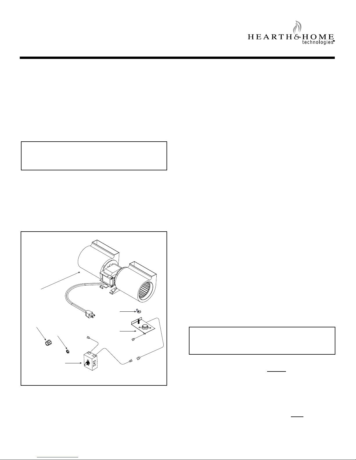
Compare system components in Figure 1 with the actual
parts received. If any parts are missing or damaged, con-
tact your dealer before starting installation. Do not install
a damaged fan kit.
Figure 1. System Components
GFK-160A Fan Kit
- Installation and Operating Instructions -
Installation Precautions
The GFK-160A Fan Kit is tested and safe when installed in
accordance with this installation manual. It is your respon-
sibility to read all instructions before starting installation and
to follow these instructions carefully during installation to as-
sure maximum benet from, and safe operation of, the fan.
This fan is carefully engineered and must be installed only
as specied. If you modify it or any of its components, you
may cause a re hazard and will void the WARRANTY. In
addition, such action may void the coverage provided by
the owner's home insurance.
CAUTION: All wiring should be done by a qualied
electrician and shall be in compliance with local
codes and with the National Electric Code ANSI/NFPA
NO. 70-current (in the United States), or with the cur-
rent CSA C22.1 Canadian Electric Code (in Canada).
SPEED
CONTROL
TEMPERATURE
SENSOR
SWITCH
WING
NUT
CONTROL
NUT
FAN
CONTROL
KNOB
CAUTION! Do not install damaged components.
Introduction
The GFK-160A fan has been designed to circulate room
air through the replace to enhance heat output. The
GFK160A fan system operates on 120 VAC, 60 Hz power.
This is available through a receptacle in the factory installed
junction box. The junction box is located in the controls
compartment of the replace.
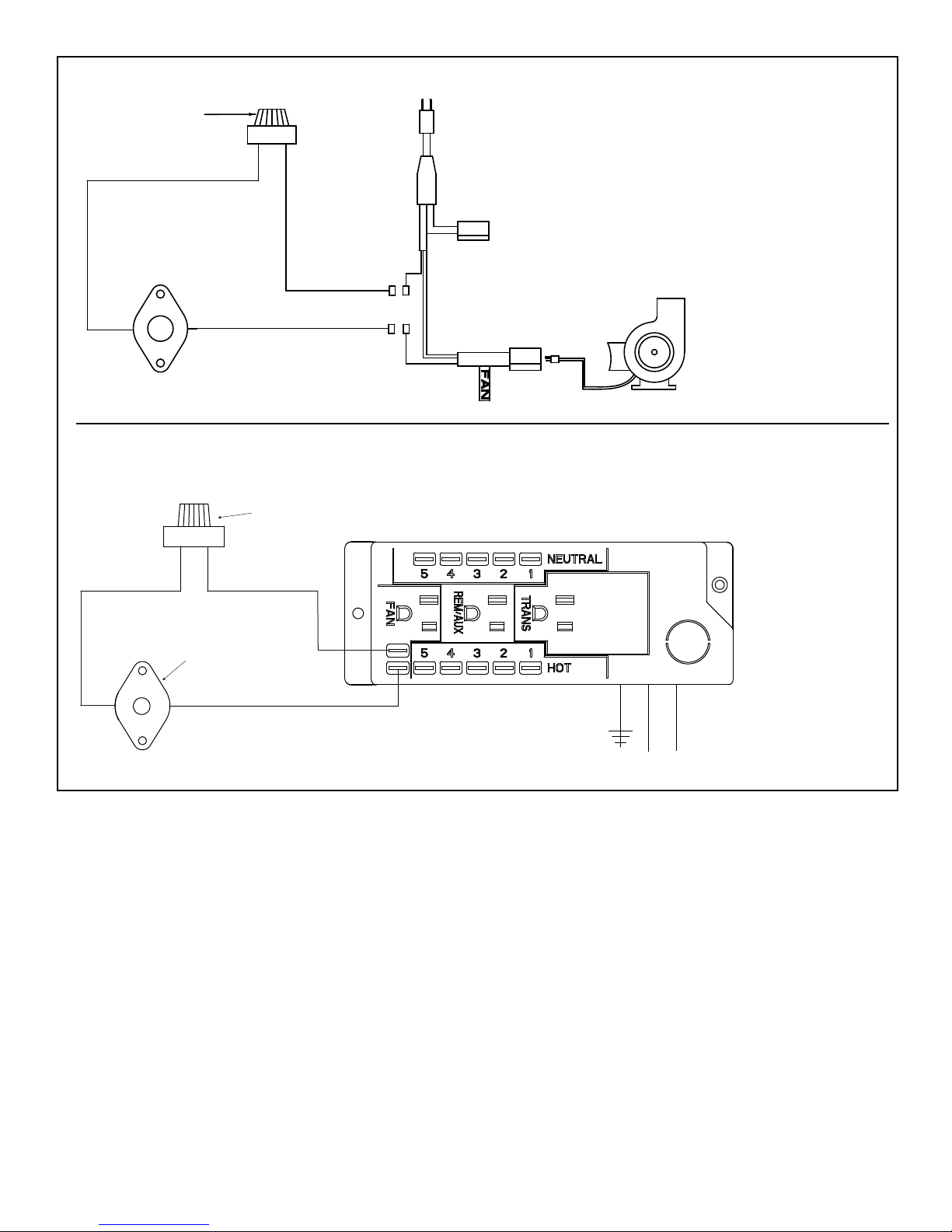
A variable speed control is provided with the fan system
to provide quiet forced air ow at the desired speeds. A
temperature sensor switch, which automatically turns the
fan ON/OFF, is also provided with this kit.
NOTE: The variable speed control and temperature
sensor switch are not used with some remote control
systems.
NOTE: Some models may have a separate mounting
location on the control panel or valve bracket for mount-
ing this speed control.
2. Slide the temperature sensor switch/bracket assembly
onto the weld stud on the outside of the combustion
chamber. Secure the bracket assembly with the wing
nut provided. See Figure 3.
NOTICE: The weld stud is located either on the lower right
side or the bottom of the combustion box.
Installation Instructions
NOTE: The factory installed junction box in the gas
replace must be wired with 110 VAC before installing
this kit. See Installation Instructions section.
Installing the Fan
Position the fan all the way to the rear and center
in the fireplace. Pull the blower forward 1/8" to 1/4"
from the back wall of the fireplace. See Figure 2.
Thread fan cord plug through hole on bottom of cord bracket
and plug into receptacle labeled "FAN" on power cord.
Installing the Speed Control and Sensor Switch
If using a remote control system that utilizes fan control,
disregard steps 1-3 and follow remote control installation
instructions.
1. Remove the knob and locknut from the variable speed
control. Slide the control behind the replace wall, in,
with the stem sticking out of the pre-punched hole which
is often in the lower right front corner. Attach the lock-
nut tightly and reattach the knob on the stem. Turn the
speed control switch to the "ON" position.
WARNING: Risk of Shock! Turn electrical power off
at the circuit breaker before beginning this installa-
tion.
NOTICE: The switch/bracket assembly must be installed
so that the sensor switch is facing the combustion box
surface.