Hearth Technologies mix back User manual
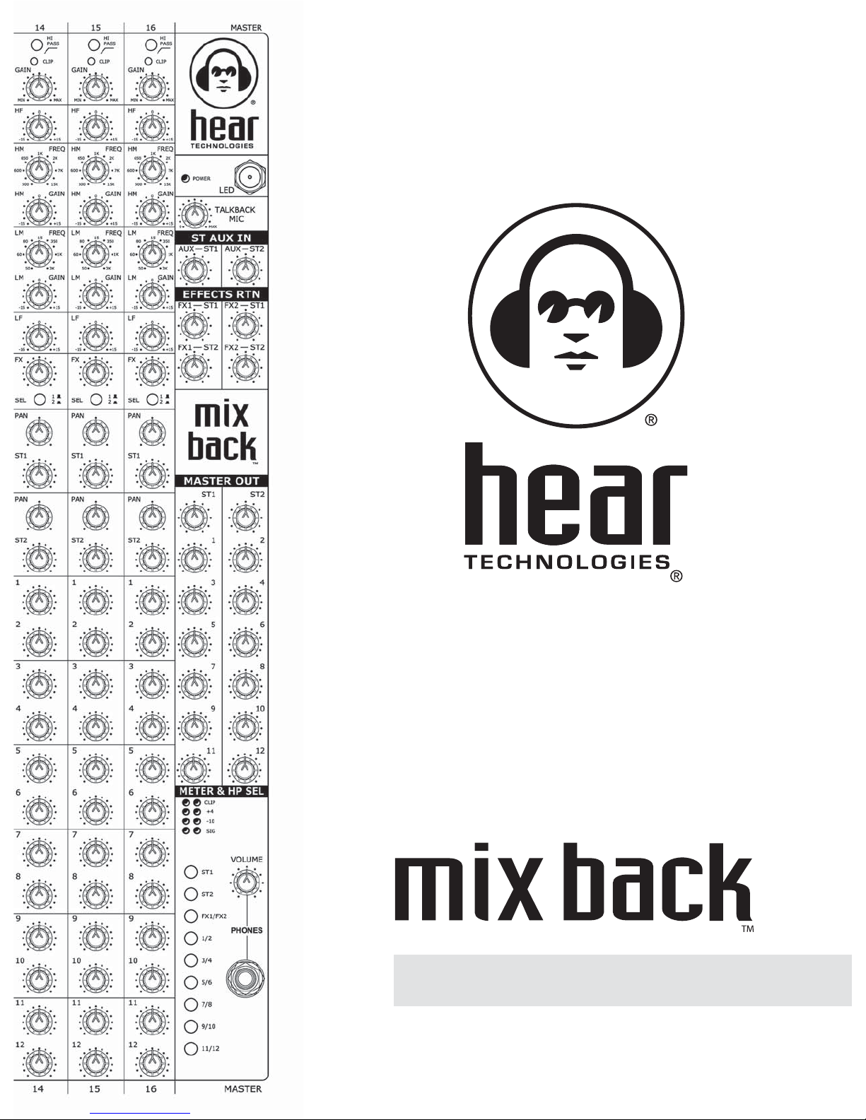
user guide


Mix Back User Guide 4
WHY?
Better Control of Your Mix
In-ear monitors (IEM) and personal monitor mixing provide several benefits above conventional
monitoring:
• No feedback – now you can EQ the vocal mic
• Greatly reduced or eliminated stage volume (yea!)
• Virtual elimination of room acoustic coloration on stage (ever played in a gymnasium?)
• Elimination of sign language between stage and sound engineer (no more semaphores!)
• Most importantly, you get to Control Your Mix®
Mix Back and Hear Back Make It Easy
With some monitor systems, it is possible for the talent to create his or her own mix. However,
there are two drawbacks of a musician mixing all of the individual mixes:
a. They don’t know what they sound like in the audience because their ears are plugged up
with in-ear monitors. Do you care what you sound like to the audience?
b. Players need to be playing, not mixing
With Hear Back, it’s as simple as turning up the "perfect mix" (front of house, recording studio
two mix, etc.) and adjusting your "more me" input(s). Simply turn the knobs and smile.
EXAMPLE: Your star vocalist should not waste time mastering an extensive system of
switches, dials, displays and cables resembling the cockpit of a 747. They just need the
"perfect mix" (channels 1 & 2) and their "more me" input. Now time and energy is where it
should be – performing!
We recommend you connect the “perfect mix” from the FOH console or studio “two mix” to the
Mix Back stereo aux input.
When using in-ear monitors the talent looses their psycho-acoustic space because stage
reflections are lost. To cure this, create a stereo mix (as perceived on stage) to help restore the
natural feel. When performing live, the “perfect mix” lets you hear what the audience hears.
Connect an ambient microphone to a Mix Back input (located near the band front line) so
the talent can hear the audience. Locating the mic far away adds an unnatural delay. Sound
travels at roughly one foot per millisecond, so a mic placed 100 feet into the audience has a 100
mSec delay. It is often necessary to add a limiter to the ambient mic channel to prevent excessive
ambient signal into the monitor mix.
INTRODUCTION TO
PERSONAL MONITOR MIXING
™
TIP
TIP
Forget everything
you’ve ever learned about
monitor mixing!

Mix Back User Guide
5
MIX BACK MIXER DESCRIPTION
Mix Back is a flexible 16 x 12 x 2 x 2 monitor
mixer. Featuring two stereo and twelve mono
busses, it’s a perfect companion for Hear Back,
as well as conventional monitoring systems
and wireless in-ear systems. Mix Back is
equally at home as a stand-alone mains and
monitor mixer.
Each channel features a signal/clip LED, Gain
control, 100 Hz hi-pass filter, four-band EQ,
switch-selectable dual effects sends, two stereo
volume and pan controls, and twelve mono
volume controls.
The master section features AFL (After Fade
Listen) meter/headphone selection, stereo
auxiliary input, and two effects returns. A
built-in talkback mic preamp permits talking to
any or all of the master outputs as well as a
balanced output using the optional
sixteen-button talkback remote.
The sixteen master outputs are available as
balanced TRS analog, ADAT, and HearBus.
Note: This equipment has been tested and found to comply with the limits for a Class B digital device, pursuant to part 15 of the FCC Rules. These limits are
designed to provide reasonable protection against harmful interference in a residential installation. This equipment generates, uses and can radiate radio
frequency energy and, if not installed and used in accordance with the instructions, may cause harmful interference to radio communications. However, there is
no guarantee that interference will not occur in a particular installation. If this equipment does cause harmful interference to radio or television reception, which
can be determined by turning the equipment off and on, the user is encouraged to try to correct the interference by one or more of the following measures:
• Reorient or relocate the receiving antenna.
• Increase the separation between the equipment and receiver.
• Connect the equipment into an outlet on a circuit different from that
to which the receiver is connected.
• Consult the dealer or an experienced radio/TV technician for help.
FCC Statement
™
•Independent Monitor control
• Frees front of house and recording
console I/O for other duties
• High quality Mic preamplifiers
• Four band EQ with quasi-parametric
sweepable mid controls
• Very low distortion
• Built-in talkback feature controllable only
with optional remote control
• Buss inputs permit linking mixers together
• Stereo Aux input assignable to ST1
and ST2
• Dual effects send/return
• Switch-selectable AFL meter/headphone
monitoring
• Analog, ADAT, and HearBus outputs
• Glow-in-the-dark knob pointers and
silkscreen
• UV LED Lamp included
• Rack Mountable (11RU)
ADVANTAGES / FEATURES
Thank you for purchasing the Hear Technologies
Mix Back!
Mix Back User Guide 6
APPLICATIONS
• Monitor Mixer
• Front of House Mixer
• Recording Studio Cue Mixer
• Post Production Mixer
• Multi-Zone Distributed Audio with Paging
MIX BACK USED AS A
STAND-ALONE LIVE SYSTEM
• Stereo FOH mix – connected via stereo
analog outputs
• Hear Back – connected via sixteen
channel HearBus outputs
• Recording – connected via the sixteen
channel ADAT outputs
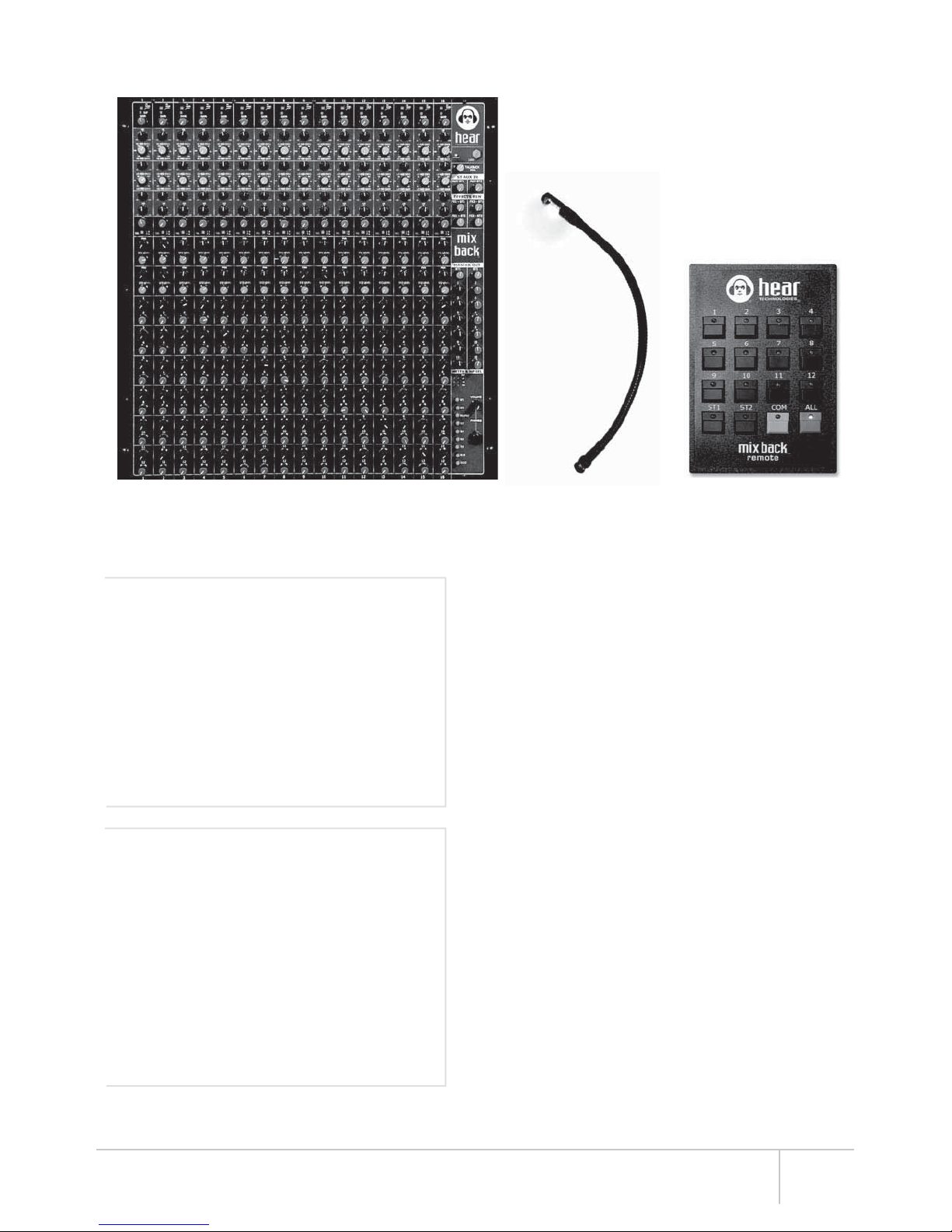
mix back mixer mix back remote
(optional)
When used in conjunction with Hear Back, the
talent has total control over cue or personal
monitor mixes. The Mix Back provides control for
effects, EQ, and a stereo baseline “perfect mix”.
Combine all that with the talkback feature and
you have a winning combination, sure to bring
smiles to the talent!
The built-in talkback function permits the band
director to talk specifically to each talent through
the individual “more me” outputs, as well as both
stereo busses.
The optional talkback remote may be connected
up to 500 feet from the Mixer using standard
CAT5e cable. The talkback (remote COM)
balanced output acts as an intercom for
communicating with the front of house engineer
or to the talent when used in a studio. The
remote COM button also activates a relay for
lighting beacons or virtually any function
needing a set of dry contacts.
UV LED lamp

Mix Back User Guide
7
• High quality Mic/Line inputs
• Passive XLR split with Pin 1 lift
• Phantom Mic power switch
• Channel insert
• Signal/Clip LED indicator
• 100 Hz high-pass filter
• Gain control
• Four-band EQ with dual sweepable mids
• Two stereo level and pan controls
(ST1 and ST2)
• Twelve mono level controls (1-12)
• Dual switch-selectable effects sends
Hi-Pass filter: Use to eliminate low frequency stage
rumble and wind noise in microphones. Use whenever
possible to prevent excessive low energy build up in
the mixer busses.
Signal/Clip LED: This indicator is post-EQ,
pre-volume.
Preamp Gain Control
HF (Hi Frequency): 10 KHz shelving EQ, +/- 15 dB
gain cut/boost
HM (Hi Mid) Frequency: Adjustable from 500 Hz to
15,000 Hz
HM Gain control: +/- 15 dB cut/boost
LM (Lo Mid) Frequency: Adjustable from 50 Hz to
3,000 Hz
LM Gain control: +/- 15 dB cut/boost
LF (Lo Frequency): 100 Hz shelving, +/- 15 dB
cut/boost
FX Level: Adjusts the effects send level
FX Select: Selects effects send 1 or 2
ST1 (Stereo 1) Pan: Use to pan input to the desired
stereo position
ST1 (Stereo 1) Level: Adjusts level to the Stereo 1
master buss
ST2 (Stereo 2) Pan: Use to pan input to the desired
stereo position
ST2 (Stereo 2) Level: Adjusts level to the Stereo 2
master buss
Mono level 1-12: Adjusts level to mono master
outputs 1 thru 12
Line Input: TRS Balanced
Phantom Mic Power
Switch: +18 VDC (powers
most condensers)
Mic Input: XLR (Pin 2 +)
Pin 1 Ground Lift:
For Output XLR
Passive Split XLR Output
Channel Insert:
Tip = Send
Ring = Return
Sleeve = Ground (SHIELD)
It is wise to cut undesirable frequencies
rather than boost desired frequencies because it
causes less ringing associated with analog EQ.
Note: Turn off the Mic
power switch if you use
FOH console or recording
console phantom power.
1
front panel rear panel
2
3
4
5
6
7
8
9
10
11
12
13
14
15
16
TIP
17
18
19
20
21
22
2
2
1
3
4
5
6
7
8
9
10
12
13
14
15
16
11
17
18
19
20
21
22
EACH INPUT CHANNEL FEATURES
32
132
132
1
1
2
3
1
2
3
1
2
3

Mix Back User Guide
9
Remote Control RJ45 Pin Outs:
Pin Function
1 Digital +
2 Digital -
3 Ground
4 +18 VDC
5 No Connect
6 Ground
7 +18 VDC
8 No Connect
1
2
3
4
5
2
3
4
5
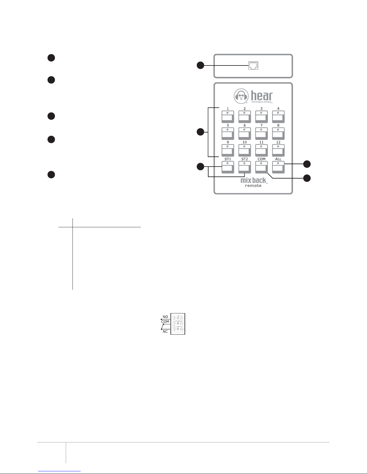
TALKBACK REMOTE CONTROL (Optional)
Remote Output: The Mix Back Remote is
connected to the Mix Back using standard
CAT5e cable. (wired 1 to 1)
Switches 1-12: Routes the talkback microphone
to the corresponding Mix Back master sections.
Very useful for talking to a particular “more me”
output. Talkback is useful for live and studio
personal cue.
ST1/ST2: When selecting ST1 and/or ST2
switches, one can talk to everyone listening to
those corresponding stereo mixes.
COM: The COM button turns on the talkback
balanced output connector on the rear panel and
closes the talkback relay (for light beacons,
dimming module for control rooms, the Talk Back
600 MV logic input, etc.).
ALL: The ALL switch permits the talkback
microphone to route to all outputs at the same
time. This can be thought of as a broadcast to
everyone connected to the Mix Back outputs.
1
Relay Output:
1 = Normally Open (Top Pin)
2 = Common (Center Pin)
3 = Normally Closed (Bottom Pin)


Mix Back User Guide
11
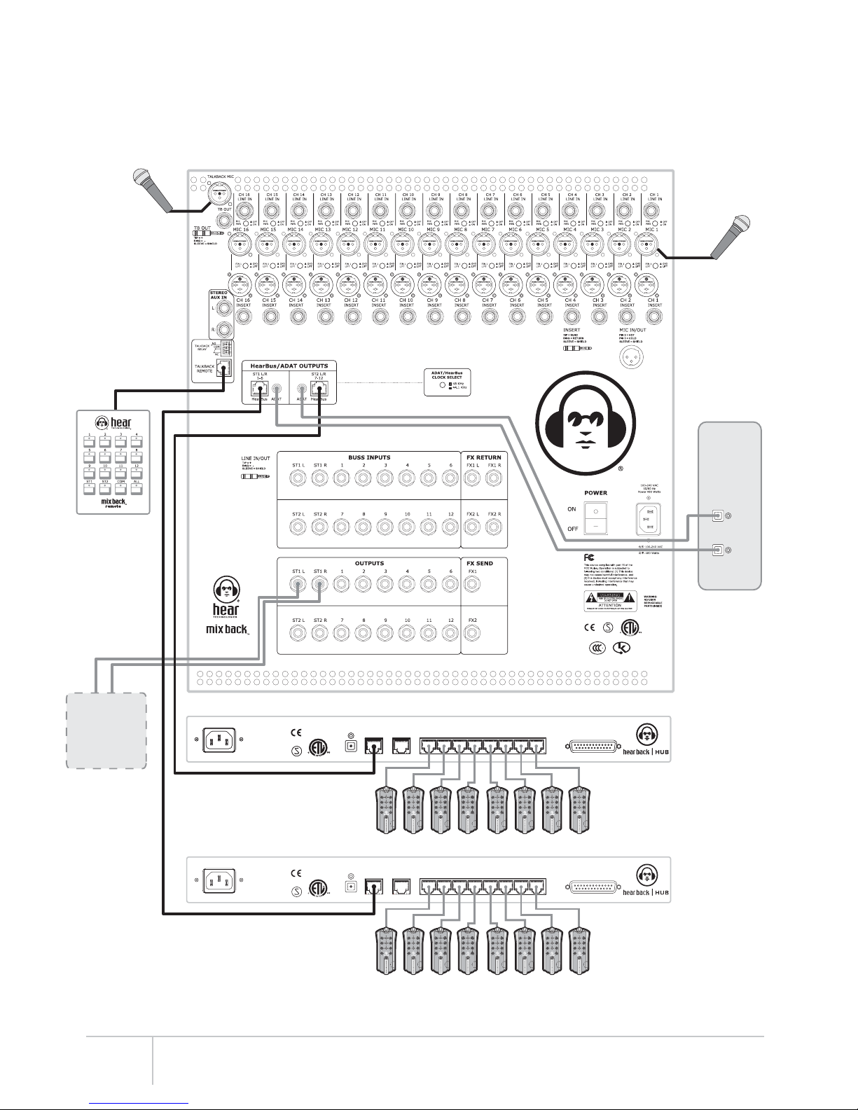
USING MIX BACK FOR PA, HEAR BACK,
AND RECORDING
1. Using the Mix Back, Hear Back and ADAT
equipped recorders at the same time (see the
hook-up diagram on page 17):
a. Connect the Mix Back HearBus outputs to
Hear Back Hub HearBus inputs.
b. Connect Stereo Master 1 analog outputs to
the PA system.
c. Connect Mix Back ADAT optical outputs to a
digital recorder with ADAT inputs.
d. Duplicate the stereo (“Perfect Mix”) on both
Stereo 1 (PA) and Stereo 2 (Hear Back) as the
base line mix for the Hear Back system(s).
This permits the performers to hear the
equivalent FOH mix as in the PA system.
e. Adjust the Mix Back mono channel (“more
me”) outputs (mono 1-12) and send them to
the appropriate “more me” Hear Back Hub
inputs. Example: if Channel 1 of the Mix Back
is the guitar player, then adjust mono volume 1
to obtain the appropriate level, turn all other
Mono volumes off. Doing this sends just the
guitar to channel three on the Hear Back Hub.
NOTE: Since Mix Back channels 1&2 are the “stereo
mix/perfect mix” and are sent to the HUB channels
1&2 then mono channels are skewed by two
channels, i.e. Mix Back channel one is channel three
on the hub, Mix Back channel two is channel four on
the hub, and so on.
IMPORTANT: When using in-ear monitors you
need a baseline stereo mix to verify what the
audience hears. Always assign the stereo mix so
it appears on every Hear Back Mixer stereo knob
(Channels 1&2). A stereo mix is critical since
ambience and physco-acoustics are absent with
in-ears. (Hey – in-ears are earplugs!)
If you are sending the perfect mix from a FOH
console, then plug that into the left/right Aux
inputs and assign them to the Hear Back output
channels ST1 and ST2.
NOTE: Reverse the left and right channels so you
have the correct stereo image on the stage. You may
feel a little strange if what you hear is a mirror image
of what you see, i.e. the guitar player is physically on
your left, but you hear him/her in your right ear (see
physco-acoustics in the glossary).
STUDIO CUE MIXING USING MIX BACK
AND HEAR BACK
1. Connect the inputs to the Mix Back so as to set
up an independent Cue Mix. Use the passive
splits to connect to your studio preamplifiers.
2. Talkback remote connection:
Connect the remote control to the Mix Back using
standard CAT5e cable. The connection will work
up to 500 feet or 152.4 meters.
CAUTION: NEVER PLUG THE MIX BACK
REMOTE INTO A HEARBUS OR HEAR
BACK MIXER CONNECTION BECAUSE AN
OVER VOLTAGE DAMAGE CAN OCCUR!
3. Using the talkback after channels have been
assigned on the Mix Back/Hear Back:
a. Label the Mix Back remote to correspond to
the Hear Back channel assignments.
b. Now you have the option to speak only to the
drummer – assuming only his/her “more me”
is turned up. This applies to all “more me”
channels.
c. The talkback feature has a balanced output
that becomes active when pressing the COM
switch on the remote. Use the talkback output
as a slate function if desired. Simply connect
the balanced talkback out to your recording
device. The COM switch also energizes the
intercom relay.
d. The ALL (broadcast) switch routes the
talkback mic to all outputs.
Mix Back User Guide
13
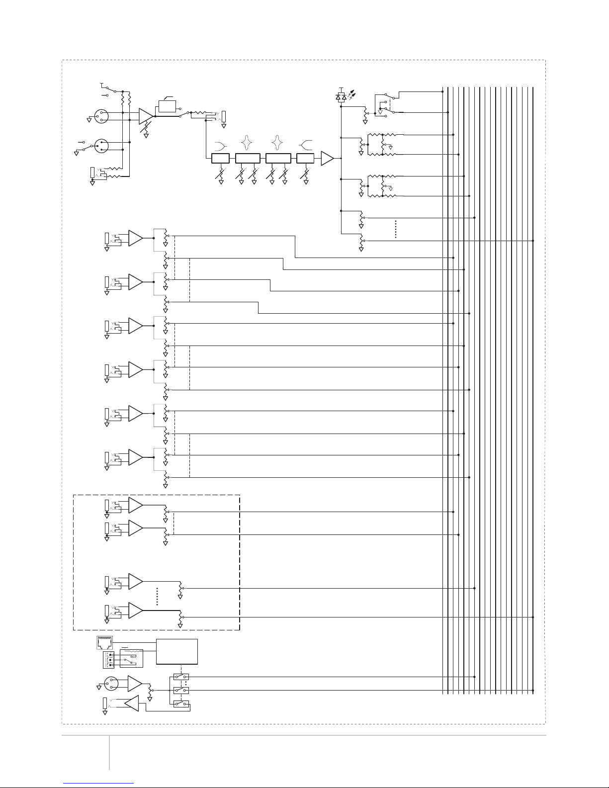
MIX BACK BLOCK DIAGRAM
TALKBACK
MIC IN
COM
NO
NC
REMOTE
CONTROL
LOGIC
MIC
IN
TRIM
INSERT
SIG/CLIP
MIC
OUT
FX 1/2
ST1
PAN
ST2
LEVEL
FX
LEVEL
MONO 1
HPF
100Hz
+
-
13
2
13
2
PIN 1
LIFT
LINE
IN
ST1
LEVEL
ST2
PAN
MONO 12
-
+
+
-
+
-
+
-
-
+
2
3
1TB
LEVEL
TALKBACK
OUT
AUX IN
LEFT
-
+
-
+
AUX IN
RIGHT
AUX L TO ST1 L
FX1 L - ST1 L
FX1 L - ST2 L
FX1 R - ST1 R
FX1 R - ST2 R
FX2 L - ST1 L
FX2 L - ST2 L
FX2 R - ST1 R
FX2 R - ST2 R
AUX L TO ST2 L
AUX R TO ST1 R
AUX R TO ST2 R
FX1 SND
FX2 SND
SELECT
ST1 L
ST1 R
ST2 L
ST2 R
MONO 1
MONO 12
+
-
-
+
BUSS IN
ST1 L
BUSS IN
ST1 R
ST1 L BUSS IN
ST1 R BUSS IN
MONO 12 BUSS IN
BUSS IN
MONO 12
+
-
-
+
BUSS IN
MONO 1 MONO 1 BUSS IN
NOTE: ONLY BUSS INPUTS ST1, MONO 1
AND MONO 12 SHOWN FOR CLARITY
INPUT CHANNEL - TYPICAL OF 16
MONO 12
MONO 1
TB
RELAY
TO
REMOTE
FX1 SND
FX2 SND
ST1 L
ST1 R
ST2 L
ST2 R
MONO 1
MONO 2
MONO 3
MONO 4
MONO 5
MONO 6
MONO 7
MONO 8
MONO 9
MONO 10
MONO 11
MONO 12
G
HI
GF
FG
HI MID
LO MID
LO
G
MONO 12
MONO 11
MONO 10
MONO 9
MONO 8
MONO 7
MONO 6
MONO 5
MONO 4
MONO 3
MONO 2
MONO 1
ST2 R
ST2 L
ST1 R
ST1 L
FX2 SND
FX1 SND
NOTE: TALKBACK ROUTES TO ALL MASTER BUSSES.
ONLY TB OUT, MONO 1, AND MONO 12 ARE SHOWN FOR CLARITY
NOTE: ONLY ST1, ST2, MONO 1, AND MONO 12 SHOWN FOR CLARITY
HI-PASS
FILTER
18 dB PAD
FX1 LEFT
RETURN
FX1 RIGHT
RETURN
FX2 LEFT
RETURN
FX2 RIGHT
RETURN
MIC PWR
+18VDC
(1 of 2)
TALKBACK
Mix Back User Guide 14
FX1 SND
FX2 SND
ST1 L
ST1 R
ST2 L
ST2 R
MONO 1
MONO 2
MONO 3
MONO 4
MONO 5
MONO 6
MONO 7
MONO 8
MONO 9
MONO 10
MONO 11
MONO 12MONO 12
MONO 11
MONO 10
MONO 9
MONO 8
MONO 7
MONO 6
MONO 5
MONO 4
MONO 3
MONO 2
MONO 1
ST2 R
ST2 L
ST1 R
ST1 L
FX2 SND
FX1 SND
ST1
LEFT
ST1
RIGHT
ST2
LEFT
ST2
RIGHT
MONO
1
MONO
2
MONO
3
MONO
4
MONO
5
MONO
6
MONO
7
MONO
8
MONO
9
MONO
10
MONO
11
MONO
12
FX2
SEND
FX1
SEND
ADAT
HEARBUS
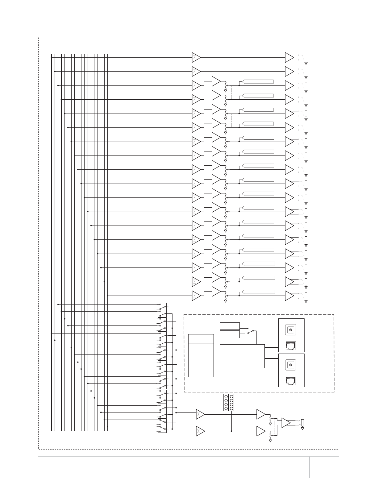
A/D CONVERTER
ADAT/HEAR BUS
LOGIC
44.1 KHz
48 KHz OUTPUT
CHANNELS
ST1 L/R
MONO 1-6
HEARBUS
ADAT
OUTPUT
METER
+13 dB
+4 dB
-10 dB
-32 dB
HEADPHONES
HP
VOLUME
AFL/HP
SELECT
MONO 11/12
MONO 9/10
MONO 7/8
MONO 5/6
MONO 3/4
MONO 1/2
ST2 L/R
ST1 L/R
FROM
VOL BUSSES
CLOCK
SELECT
ST1 L VOL BUSS
MONO 1 VOL BUSS
ST1 R VOL BUSS
ST2 L VOL BUSS
ST2 R VOL BUSS
MONO 2 VOL BUSS
MONO 3 VOL BUSS
MONO 4 VOL BUSS
MONO 5 VOL BUSS
MONO 6 VOL BUSS
MONO 7 VOL BUSS
MONO 8 VOL BUSS
MONO 9 VOL BUSS
MONO 10 VOL BUSS
MONO 11 VOL BUSS
MONO 12 VOL BUSS
FX1 SEND
FX2 SEND
ST1 RIGHT
ST1 LEFT
ST2 LEFT
ST2 RIGHT
MONO 1
MONO 2
MONO 3
MONO 4
MONO 5
MONO 6
MONO 7
MONO 8
MONO 9
MONO 10
MONO 11
MONO 12
LOCATED
ON FRONT PANEL
1 OF 9
GANGED SWITCH
OUTPUT
CHANNELS
ST2 L/R
MONO 7-12
(2 of 2)
MIX BACK BLOCK DIAGRAM

Mix Back User Guide
15
1
2
3
32
1
1
2
3
32
132
132
132
132
132
132
132
132
132
132
132
132
132
132
1
1
2
3
1
2
3
1
2
3
1
2
3
1
2
3
1
2
3
1
2
3
1
2
3
1
2
3
1
2
3
1
2
3
1
2
3
1
2
3
1
2
3
1
2
3
WARNING:
NO USER SERVICEABLE
PARTS INSIDE
ADAT IN HearBus
IN
NOT FOR MIXER
MIXER OUTPUTS ANALOG INPUTS
HearBus
OUT
NOT FOR MIXER MIXER OUTPUTS DA-88 ANALOG CABLE
FUSE: 1A @ 115VAC,
0.5A @ 230VAC
50 / 60 Hz
TM
WARNING:
NO USER SERVICEABLE
PARTS INSIDE
ADAT IN HearBus
IN
NOT FOR MIXER
MIXER OUTPUTS ANALOG INPUTS
HearBus
OUT
NOT FOR MIXER MIXER OUTPUTS DA-88 ANALOG CABLE
FUSE: 1A @ 115VAC,
0.5A @ 230VAC
50 / 60 Hz
TM
To DAW or
to recording
Studio Preamps
Mix Back
Talkback
Remote
Mix Back Mixer
Talkback
Mic
Hear Back Hub
Hear Back Hub
HOOK-UP DIAGRAM STUDIO
DAW or Recorder
“Two Mix”
Up to 8 Mixers
Up to 8 Mixers
Mix Back User Guide 16
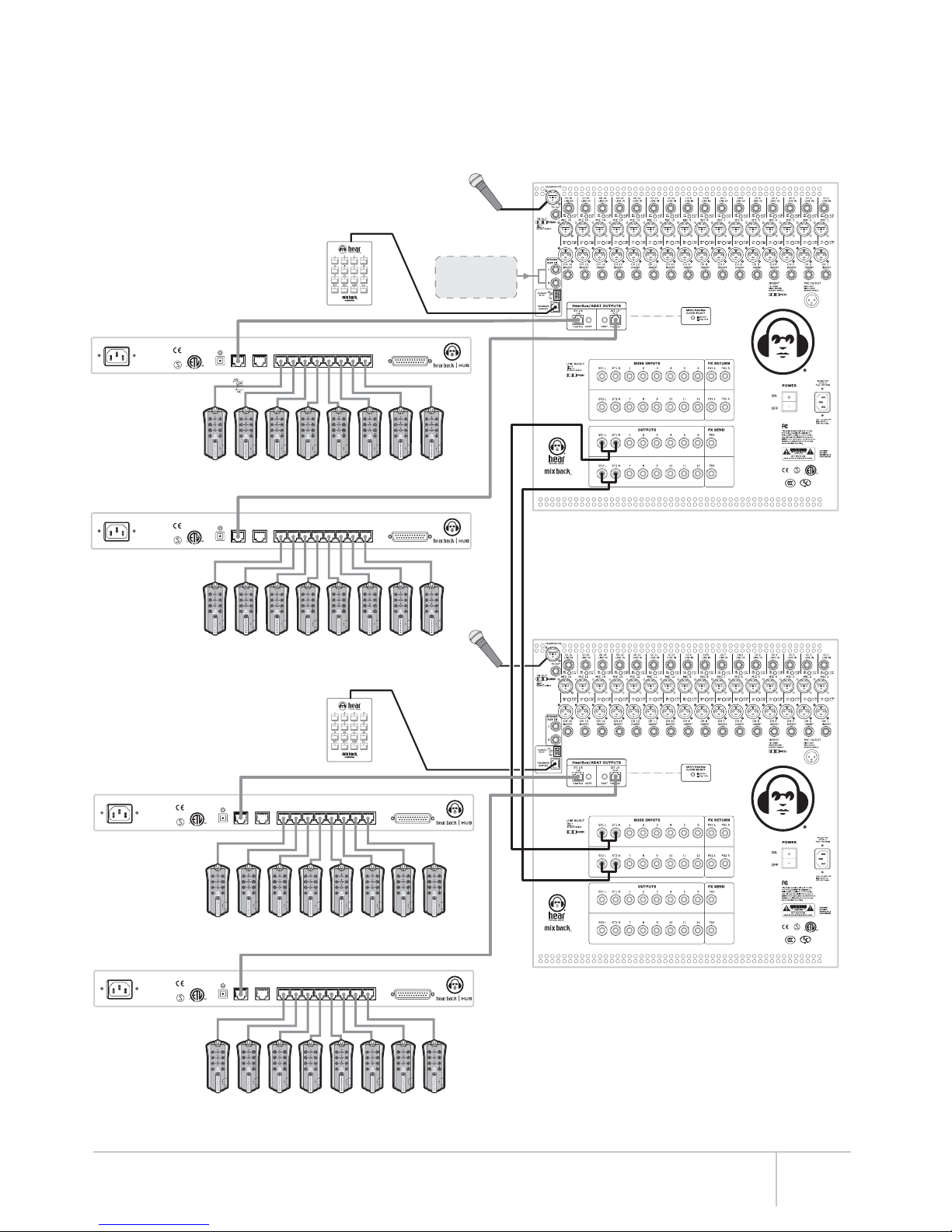
TWENTY-FOUR “MORE ME” CHANNELS USING
TWO MIX BACKS AND FOUR HEAR BACK HUBS
1
2
3
32
1
1
2
3
32
132
132
132
132
132
132
132
132
132
132
132
132
132
132
1
1
2
3
1
2
3
1
2
3
1
2
3
1
2
3
1
2
3
1
2
3
1
2
3
1
2
3
1
2
3
1
2
3
1
2
3
1
2
3
1
2
3
1
2
3
WARNING:
NO USER SERVICEABLE
PARTS INSIDE
ADAT IN HearBus
IN
NOT FOR MIXER
MIXER OUTPUTS ANALOG INPUTS
HearBus
OUT
NOT FOR MIXER MIXER OUTPUTS DA-88 ANALOG CABLE
FUSE: 1A @ 115VAC,
0.5A @ 230VAC
50 / 60 Hz
TM
1
2
3
32
1
1
2
3
32
132
132
132
132
132
132
132
132
132
132
132
132
132
132
1
1
2
3
1
2
3
1
2
3
1
2
3
1
2
3
1
2
3
1
2
3
1
2
3
1
2
3
1
2
3
1
2
3
1
2
3
1
2
3
1
2
3
1
2
3
WARNING:
NO USER SERVICEABLE
PARTS INSIDE
ADAT IN HearBus
IN
NOT FOR MIXER
MIXER OUTPUTS ANALOG INPUTS
HearBus
OUT
NOT FOR MIXER MIXER OUTPUTS DA-88 ANALOG CABLE
FUSE: 1A @ 115VAC,
0.5A @ 230VAC
50 / 60 Hz
TM
WARNING:
NO USER SERVICEABLE
PARTS INSIDE
ADAT IN HearBus
IN
NOT FOR MIXER
MIXER OUTPUTS ANALOG INPUTS
HearBus
OUT
NOT FOR MIXER MIXER OUTPUTS DA-88 ANALOG CABLE
FUSE: 1A @ 115VAC,
0.5A @ 230VAC
50 / 60 Hz
TM
WARNING:
NO USER SERVICEABLE
PARTS INSIDE
ADAT IN HearBus
IN
NOT FOR MIXER
MIXER OUTPUTS ANALOG INPUTS
HearBus
OUT
NOT FOR MIXER MIXER OUTPUTS DA-88 ANALOG CABLE
FUSE: 1A @ 115VAC,
0.5A @ 230VAC
50 / 60 Hz
TM
Up to 8 Mixers
Mix Back Mixer 1
Hear Back Hub 4
Mix Back Mixer 2
Hear Back Hub 3
Hear Back Hub 2
Hear Back Hub 1
Up to 8 Mixers
Up to 8 Mixers
Up to 8 Mixers
Mix Back
Talkback
Remote
HOOK-UP DIAGRAM
Mix Back
Talkback
Remote
“Stereo Mix” from
FOH Console or
Studio “Two Mix”
Ta l k b a c k
Mic
Talkback
Mic
1
2
3
32
1
1
2
3
32
132
132
132
132
132
132
132
132
132
132
132
132
132
132
1
1
2
3
1
2
3
1
2
3
1
2
3
1
2
3
1
2
3
1
2
3
1
2
3
1
2
3
1
2
3
1
2
3
1
2
3
1
2
3
1
2
3
1
2
3
WARNING:
NO USER SERVICEABLE
PARTS INSIDE
ADAT IN HearBus
IN
NOT FOR MIXER
MIXER OUTPUTS ANALOG INPUTS
HearBus
OUT
NOT FOR MIXER MIXER OUTPUTS DA-88 ANALOG CABLE
FUSE: 1A @ 115VAC,
0.5A @ 230VAC
50 / 60 Hz
TM
Digital
Recorder
or DAW
Mix Back
Talkback
Remote
Mix Back Mixer
Talkback
Mic
PA
System
Hear Back Hub
WARNING:
NO USER SERVICEABLE
PARTS INSIDE
ADAT IN HearBus
IN
NOT FOR MIXER
MIXER OUTPUTS ANALOG INPUTS
HearBus
OUT
NOT FOR MIXER MIXER OUTPUTS DA-88 ANALOG CABLE
FUSE: 1A @ 115VAC,
0.5A @ 230VAC
50 / 60 Hz
TM
WARNING:
NO USER SERVICEABLE
PARTS INSIDE
ADAT IN HearBus
IN
NOT FOR MIXER
MIXER OUTPUTS ANALOG INPUTS
HearBus
OUT
NOT FOR MIXER MIXER OUTPUTS DA-88 ANALOG CABLE
FUSE: 1A @ 115VAC,
0.5A @ 230VAC
50 / 60 Hz
TM
Hear Back Hub
Hear Back Hub
HOOK-UP DIAGRAM LIVE PA, HEAR BACK, AND RECORDING
Up to 8 Mixers
Up to 8 Mixers
Mix Back User Guide
17
1
2
3
32
1
1
2
3
32
132
132
132
132
132
132
132
132
132
132
132
132
132
132
1
1
2
3
1
2
3
1
2
3
1
2
3
1
2
3
1
2
3
1
2
3
1
2
3
1
2
3
1
2
3
1
2
3
1
2
3
1
2
3
1
2
3
1
2
3
Multi-channel Stereo Amplifier
Left
1
Right
1
Left
2
Right
2
Left
3
Right
3
Left
4
Right
4
Left
5
Right
5
Left
6
Right
6
Left
7
Right
7
Left
8
Right
8
Stereo Multi-channel Music Source
Left
1
Right
1
Left
2
Right
2
Left
3
Right
3
Left
4
Right
4
Left
5
Right
5
Left
6
Right
6
Left
7
Right
7
Left
8
Right
8
Not connected for clarity
Mix Back
Mixer
SPKR 8
R / Out
SPKR 8
L / Out
SPKR 1
R / Out
SPKR 1
L / Out
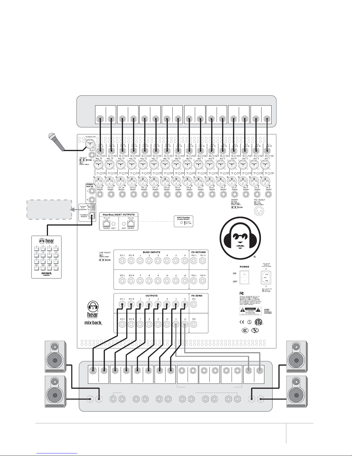
MULTI-ZONE BACKGROUND / FOREGROUND
MUSIC WITH PAGING
Mix Back
Talkback
Remote
For Zoned Paging
Talkback
Mic
Mix Back works great as a zoned music system with
paging. You can have up to eight stereo sources
and zones, or up to fourteen mono zones and
sources. When using mono zones, paging (talkback)
occurs on both left and right of the two stereo (ST1
L/R and ST2 L/R) outputs.
Note: Paging (talkback) does not duck the music,
but it is adjustable to overcome the music.
The talkback Intercom relay can trigger other
devices, such as pre-recorded messages, lamps, or
other control device.
Relay contacts for
dimming music
source (if available)
Zone 8 Zone 1
Speaker zones 2-7 not shown for clarity
Mix Back User Guide 18
HOOK-UP DIAGRAM

1
2
3
32
1
1
2
3
32
132
132
132
132
132
132
132
132
132
132
132
132
132
132
1
1
2
3
1
2
3
1
2
3
1
2
3
1
2
3
1
2
3
1
2
3
1
2
3
1
2
3
1
2
3
1
2
3
1
2
3
1
2
3
1
2
3
1
2
3
Equalizer
Left
1
Right
2
Left
3
Right
4
Left
5
Right
6
Left
7
Right
8
Left
9
Right
10
Left
11
Right
12
Left
13
Right
14
EQ
R / Out
EQ
L / Out
EQ
R / Out
EQ
L / Out
CONVENTIONAL MONITOR MIXING
(UP TO FOURTEEN MONITORS)
1. Connect microphone or line inputs
to the Mix Back input channels.
2. Connect the mic outputs to the
FOH board.
3. Connect the Mix Back Master
outputs to an equalizer, and then
the equalizer outputs to the power
amps or powered monitors.
Adjust all input channels “Mono Level
1” to the Master 1 output to obtain the
mix for that monitor. Repeat for all
twelve mono Master outputs.
Pan all ST1 and ST2 pan controls full
left (or right) and the ST1 or ST2 level
controls to derive the two additional
mono monitor mixes.
To FOH Mixer
Not connected for clarity
EQ In
Powered MonitorsPowered Monitors
Optionally, you may use ST1
and ST2 outputs to derive two
stereo monitor mixes. This
option yields twelve mono
mixes and two stereo mixes.
Not connected for clarity
Mix Back Mixer
Mix Back
Talkback
Remote
Talkback
Mic Mic In
HOOK-UP DIAGRAM
Mix Back User Guide
19
Table of contents


