Inkel SYSTEM 800 User manual
Penta
é
meenaeee
|
Sidalaonctcrca
a:
;
a
Sane
any
pee
i
rari
nae
MIO
A
SS

Unpacking
and
Installation
Although
it
is
neither
complicated
to
install
nor
difficult
to
operate
your
Audio
Mixer,
a
few
minutes
of
your
time
is
required
to
read
this
manual
for
a
properly
wired
installation
and
becoming
familiar
with
its
many
features
and
how
to
use
them.
Please
take
a
great
care
in
unpacking
your
Mixer
and
do
not
discard
the
carton
and
other
packing
materials.
They
may
be
needed
when
moving
your
set
and
are
required
if
it
ever
becomes
necessary
to
return.
your
set
for
service.
Never
place
the
unit
near
radiators,
in
front
of
heating
vents,
to
direct
sun
light,
in
excessively
humid
or
dusty
location
to
avoid
early
damage
and
for
your
years
of
quality
entertainment.
Connect
your
complementary
components
as
illus-
trated
in
the
following
page.
Feature
of
Audio
Mixer
SYSTEM
800
8
CHANNEL
INPUTS
AND
2
CHANNEL
OUTPUTS
AMPLIFIERS
ARE
INCORPORATED:
Any
sound
source
of
microphones,
turntables,
cassette
decks,
and
electric
guitars
can
be
applied
to
the
four
input
CH
1-4,
and
turntables,
cassette
decks,
can
be
applied
to
the
four
input
CHS5-8.
TONE
CONTROL
Adjustment
of
TREBLE
and
BASS
controls
for
the
acoustic
characteristics
of
microphones,
speakers
and
room
structure.
|
PANPOT
FOR
STEREO
EFFECT
You
can
distribute
the
signal
level
from
each
input
source
between
left
and
right
output
to
make
a
stereo
sound
ef-
{ect
ECHO
FUNCTION
To
make
the
effect
of
echo
soundon
CH
1-4,
SYSTEM
800
employs
BBD
(Bucket
Brigade
Devices)
IC.
/
You
can
individually
adjust
the
echo
volume
level
of
CH
1-4,
and
adjust
the
level
as
a
whole
with
Echo
Master.
MONITOR
You
can
monitor
the
output
or
the
program
of
individual
channel
before
from
channel
fader
stage
by
headphone.
ELECTRO-START
FUNCTION
Channel
faders
of
CH
5/6,7/8
are
provided
with
electro-start
function
to
control
AC
power
automatically
to
the
AC
outlet
on
the
rear
panel..

Rear
Panel
Connections
Speaker
Speaker
Turntable
|----e00--@
@
Amplifier
Turntable
Supply
for
Turntable
Electric
Guitar
AC
Power
Microphone
Speaker
Speaker
Cassette
Deck
i
@@---ef
alee
a___}
|----ece--0
@
Amplifier
Tuner

Rear
Panel
Feature
1.
ACINPUT
CORD
Plug
this
AC
INPUT
CORD
into
AC
outlet.
2.
AC
OUTLETS
FOR
TURNTABLES
You
can
turn
the
turntables
which
are
connected
to
this
outlets
ON
or
OFF
by
using
the
Electro-start
function
of
CH
5/6,7/8.
3.
LINE
OUT
Signal
from
these
OUTPUT
jacks
are
to
be
connected
to
LINE
IN
jacks
or
TAPE
IN
jack
if
necessary
on
the
amplifiers.
4.
MIC/MIC
ATT
INPUT
These
input
jacks
are
to
be
connected
with
microphone.
When
CH
1,2
are
selected
MIC
ATT,
they
are
to
be
connected
with
electric
guitar
etc.
5.
LINE/PHONO
INPUT
These
input jacks
are
to
be
connected
with
deck,
tuner
etc.
When
CH
3,4
are
selected
PHONO,
they
are
to
be
connected
with
turntables.
6.
LINE
INPUT
These
stereo
inputs
are
to
be
connected
with
deck,
tuner
etc.
7.
PHONO
INPUT
These
stereo
inputs
are
to
be
connected
only
with
turntables.
8.
GROUND
TERMINAL
This
terminal
is
to
be
connected
to
the
ground
terminal
of
turntable
to
reduce
hum
to
minimum.
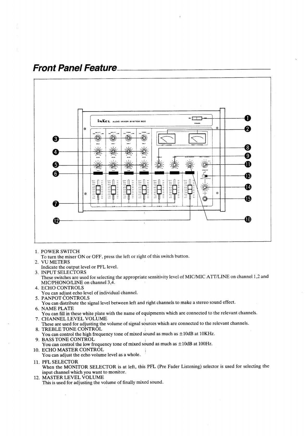
Front
Panel
Feature
10,
ii.
2.
K
aa
(aed
Ba
INREL
avuoio
mixeER
SYSTEM
800
POWER
carr
»
-
.
oe
PT
peel
or
La&e|t
c.
T
CHANNEL
o's
>
?
.
‘
a
.
.
‘
.
.
*
°
a0
o
14
es
10
°
ac
ec ec
En
ee
ee
See
te
ritsiitaiie
bpbetyuddea
beeriuguial
rigddiiita itiiiiiith
3
Jf
:
©:
©:
:
:
ea
(RASA
SAR:
a
ee
es
ee
mae
(<o)
.
POWER
SWITCH
To
turn
the
mixer
ON
or
OFF,
press
the
left
or
rignt
of
this
switch
button.
.
VU
METERS
Indicate
the
output
level
or
PFL
level.
.
INPUT
SELECTORS
These
switches
are
used
for
selecting
the
ap
TOnaae
sensitivity
level
of
MIC/MIC
ATT/LINE
on
channel
1,2
and
MIC/PHONO/LINE
on
channel
3,4.
.
ECHO
CONTROLS
You
can
adjust
echo
level
of
individual
channel.
.
PANPOT
CONTROLS
You
can
distribute
the
signal
level
between
left
and
right
channels
to
make
a
stereo
sound
effect.
.
NAME
PLATE
You
can
fill
in
these
white
plate
with
the
name
of
a
which
are
connected
to
the
relevant
channels.
.
CHANNEL
LEVEL
VOLUME
These
are
used
for
adjusting
the
volume
of
signal
sources
which
are
connected
to
the
relevant
channels.
.
TREBLE
TONE
CONTROL
You
can
control
the
high
frequency
tone
of
mixed
aun
as
much
as
+10dB
at
10KHz.
.
BASS
TONE
CONTROL
You
can
control
the
low
frequency
tone
of
mixed
sound
as
much
as
+10dB
at
100Hz.
ECHO
MASTER
CONTROL
|
You
can
adjust
the
echo
volume
level
as
a
whole.
PFL
SELECTOR
When
the
MONITOR
SELECTOR
is
at
left,
this
PFL
(Pre
Fader
Listening)
selector
is
used
for
selecting
the
input
channel
which
you
want
to
monitor.
MASTER
LEVEL
VOLUME
This
is
used
for
adjusting
the
volume
of
finally
mixed
sound.
13.
MONITOR
SELECTOR
This
is
used
for
selecting
PFL
signal
or
Output
signal
which
you
want
to
monitor.
14.
HEADPHONE
LEVEL
VOLUME
This
is
used
for
adjusting
the
volume
level
of
headphone
monitoring.
IS.
HEADPHONE
JACK
This
jack
is
used
for
headphone
when
you
are
monitoring.
*
CH
5/6,7/8
are
provided
with
electro-start
function
which
can
switch
AC
outlets,
and
designed
for
stereo
function.
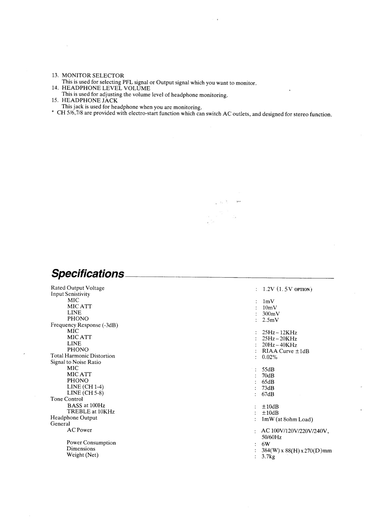
Specifications
Rated
Output
Voltage
Input
Senistivity
MIC
MIC
ATT
LINE
PHONO
Frequency
Response
(-3dB)
MIC
MIC
ATT
LINE
PHONO
Total
Harmonic
Distortion
Signal
to
Noise
Ratio
MIC
MIC
ATT
PHONO
LINE
(CH
1-4)
LINE
(CH
5-8)
Tone
Control
BASS
at
100Hz
TREBLE
at
10KHz
Headphone
Output
General
AC
Power
Power
Consumption
Dimensions
Weight
(Net)
1.2V
(1.5V
opTION)
lmV
10mV
300m
V
2.5mV
25Hz~—
12KHz
25Hz
—20KHz
20Hz
—
40KHz
RIAA
Curve
+1dB
0.02%
55dB
70dB
65dB
73dB
67dB
+10dB
+10dB
1ImW
(at
80hm
Load)
AC
100V/120V/220V/240V,
50/60Hz
6W
384(W)
x
88(H)
x270(D)mm
3.7ke

Schematic
Diagram
cH
x
Ge
ae
gee
png
ae
gt
aie
te
nae
ad
7
R128
MIC
(tmV
©
a
rd
P
4003517810
td)
ile
J
dh
Sa
POWER
BD.
OO
/
=
OD
tee
my
jr2h
Rio
£8
Line(soomv)
(
}
O
O
a
i
‘9
8.6K
ba
a
131
279
O
|
OUTPUT
CH2
A
LEFT(1L.2v)
MIC
(nv)
Sees
MIC
ATT(
cio2
ry
:
|
1/80
|
LINe@BOOmv
)
©sz
4.7/80
3
$3x
23m
cos
BP
18
etal
ej2
e#;"
e
R112
180K
i=
RIGHTUL2V)
cioe
2200p
S
|
So
=_
—
OO
ris
Kk
6
|
="
3
of
oe
L
7ORS030
ss
O
7%
10OKB
cH
8
74
C
sch
im)
{
i
|
E
£
ex
|
8
|
PHONO
(2.5mv)
(C9
O
\,
HE
ADPHONE
LINE
(
300mv)
“a
ro!
{
|
330K
g
cH
4
|e
MIC(tmv)
|
i
|
IC
NJN4556
|
{
PHONO(2.5
mv?
LINE
(BOOmv
)
VR6Otb
20KA
°
0.00!
{00027
ax
R214
R26
t
28
O33
330K
of
ou
~
21.5V
R701
C701
a
=
R3I9
(419)
EQ+
E
BCE
EN
zn
=
VU
METER
c
CHS(CH?)-LEFT
Bg
88
a
oes
LEFT
8
280880
ms
ye)
C301
(401)
gn
8
zSCiB18
PHONDL2.Sam
()
=
=
C309
(408)
R315(415)
8
8
PTR,
PTR2,DOO!,
DOO2,
D004
,D00S
:
IN4002
3
rs
D003
:
WZ
240
LINE(Z0Omy:
Ms
4
RBIT
(417)
a4
«
2
D701,
0702,
D703,
D704
:
IN6O
Cs
D80!,0802
;
CDG
24
TROO!
|
28De80Y
TROOZ
,
TROOS,
TR6O3
,TREOG,
TRTO!,TR702,
TROOI,
TROOZ
:
2SCI815
TREOI,TREO2
:
28C732TM
ICIO1,
1201,
1C3O1,1C401,
ICSOt,
1C502
,
ICBO!
|
NUM
4558
{C802
:
MN
BOOT
1C803:
MN
SIO!
VRBO
10
(-4
Ia}
R702
CTO2
Mt
CHE
(CHS)-
RIGHT
ie
eal
OO
R3I6
IG)
ISK
A
For
EUROPE
Version
AC
220V
/SOnz
R318
(418)
amK
3.3m
2
3
C3
3
3
m
3
R302
402)
3.9K
R304(404)
R
308(408)
RBIO(410)
4003517800
MAIN
BD.
ns
AC
OUTLET
1
(SWITCHED
CH
5/6)
SOW
MAX
A
AC
OUTLET
2
0.0047
O
|
(switcHen
cH
7/8)
a00VAC
()
sow
MAX
<<
TROO2
A
|.
Resistance
volues
ore
indicated
ohms
unless
otherwise
specified.
(K=1
000
,
M=1,000,000)
2.Capacitence
vaiwes
ore
shown
in
microfered
uniess
ofherwise
noted
.(
P=
micro-microfereds
)
For
UL,
CSA
AY
POWER
TRANS
pera
vanes
are
mee
—
change
without
notices,
ALIZ0V
SOs
,
x
_seneee
ere
roference
ground
under
the
following
cogditions.
Gore
OC
:
No
signal
except
where
indicated.
AC
-
RNS
5.
The
mork
found
on
some
component
parts
of
indicates
the
importance
of
the
sofety
of
the
part.
Trerefore
,
when
repiocing,
be
sure
to
use
parts
of
identico!
designation.
NOTE
:
Table of contents
Other Inkel Music Mixer manuals


