7205967-01
Note: When rst turned on wait about 1 1/2minutes for
the circuitry to calibrate.
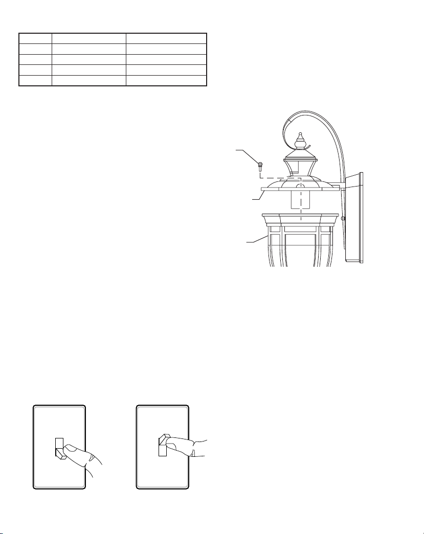
Mode: On-Time Works: Day Night
Test 5 Seconds x x
Auto 1, 5, or 10 x
Accent x
Manual x
Turn Switch OFF for
1 to 2 seconds Turn Switch
Back ON
CARE AND MAINTENANCE
and a soft damp cloth only.
light xture.ey could cause a premature deterioration
of the nish.is is not a defect in the nish and will not
be covered by the warranty.
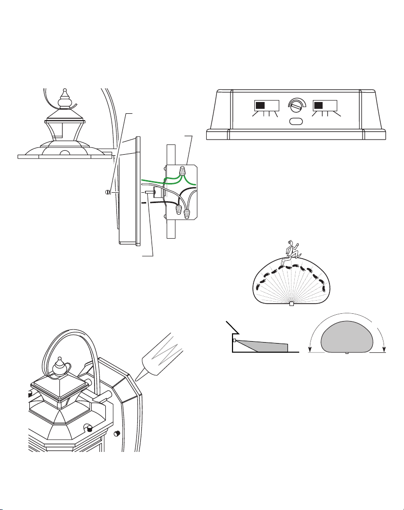
OperatingModes
Motion Sensor (AUTO) – is light xture is designed
to automatically turn on when the sensor detects a tem-
perature dierence moving across the front of the motion
sensor. e light will turn o automatically after a set
to 1, 5, or 10 minute setting and the wall switch should
be left in the ON position at all times.
Optional DualBrite® Control – is optional feature
allows the light xture to turn on at a lower light level
after dusk (sunset) for the amountoftimeselected.When
motion is detected,the lights will turn on full bright.is
continue to work in AUTO mode.
Manual Mode – is light can be activated to stay on full
bright after dusk (sunset) for only one night at a time. It
automatically resets to motion sensing at dawn (sunrise).
Note: If
power to the light xture is o for more than 5 seconds,
allow the electronic circuitry in the sensor to calibrate
(90 seconds) prior to switching to manual mode.
the wall switch for 1 to 2 seconds and then back on.
2. To return to AUTO mode, switch the light o at the
wall switch for 1 to 2 seconds and then back on.
Note: e sensor will also reset to AUTO mode at
sunrise.
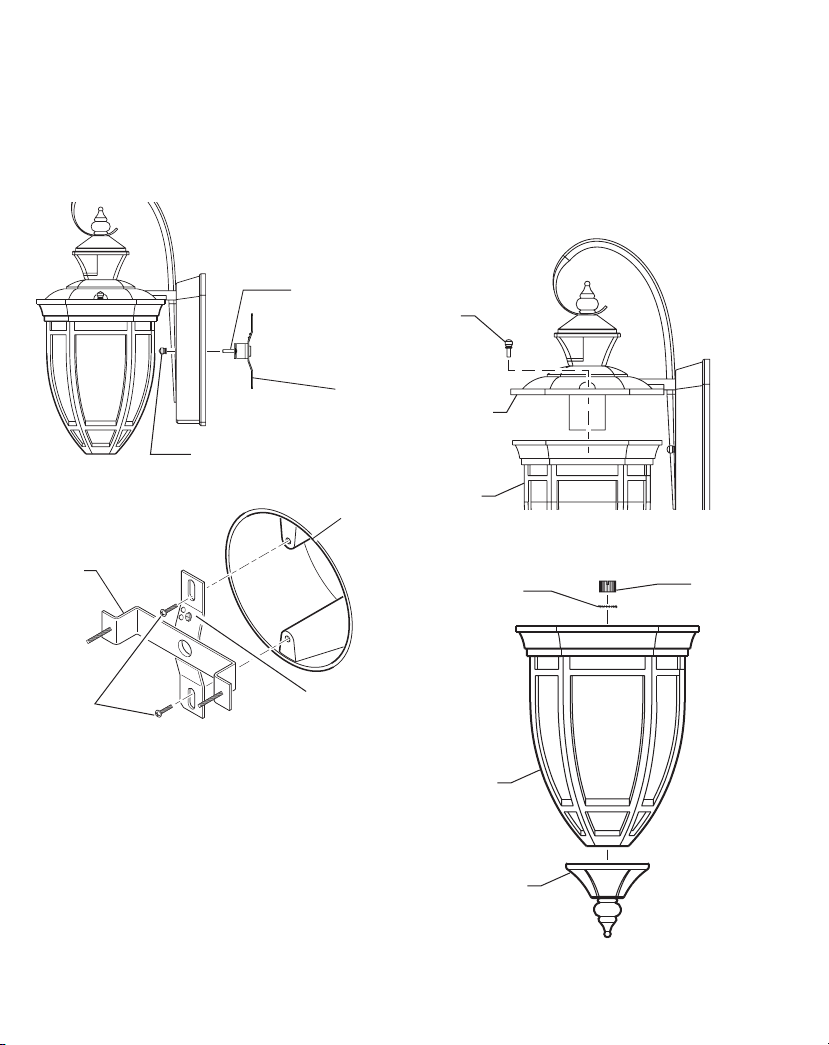
BULB REPLACEMENT
1. While holding the globe assembly with one hand,
remove the two decorative screws on top of xture cap
with the other.
2. Replace bulb (tungsten incandescent, medium base,
type “A”, 100 watt maximum).
4. Replace globe assembly onto xture.
5. Secure with decorative screws.
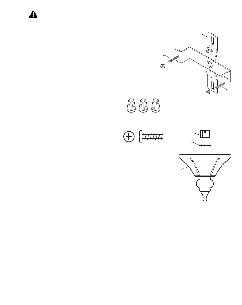
Decorative
Screw
Fixture Cap
Globe
Assembly
Remove Globe Assembly