HEATMKIT b
Page 4DA
fiTROM
CIRCUIT DESCRIPTION
_ItI4II I IIIIII1I«IIII IIIIIIIIIII•II IIIIIIIIII I »IIIIIIIt•l*II•II111tl1II•li•IIIIIiItIlI*'•<
LEFT CHANNEL PREAMPLIFIER
ai•)i*ii*MIiiiiit•»i iM11)iMivf
IUMII I1IMIHI iII l< Ml
LEFT CHANNEL POWER AMPLIFIER
h-
3
CL
z
:z
-z
:<
-i
:u
AUX
TUNER
XTAL PHONO
:“MAG. PHONO
y
t
VCW
y
6EU7
^I1I1III«fl IIIIIIIIII I IfIIIIIIiIIII*IIII| | I!IIII||IIIAIIIIIIII|I I 1IMIIIIII•IIIIIIIII4I I II*«II•IiXl1191 v1*114111 11 1*11•11
SOURCE
SELECTOR MC
SELE'
IDE 1
CTOR |
VI B1/2 6EU7 TONE CONTROL jV6 6AN6 V7 EL 84
V3 6AU6 NETWORK !1ve EL84 LEFT
"SPEAKER
i•11•i*1111m11*»11111 1 1 1 11111111»111111111111111*
£». I I IIIIIfII II«IIII1II•III III»1II I tI»I»II«»M«I4 I IIIIt I1(ItI•IiIII*IMt
-to
tHAUX
:o.
:z
=uJ TUNER
:z
:z
-<
E5XTAL PHONO
:h
:5
:gMAG. PHONO
-0£
RIGHT CHANNEL PREAMPLIFIER
t
CW V2B 1/2 6EU7
V4 6AU6 [TONE CONTROL
NETWORK
ll lIIIill 1IIIII I*Iit I I I I II IIII IIIt 11II II) II«IM1 I 1
»
RIGHT CHANNEL POWER AMPLIFIER
L| V5 6AN8 |—»|
V9 EL84
V10 EL84 RIGHT
SPEAKER
V2A 1/2 6EU7
11i11>t11111i•111 1 ii i •1111111r111iii i•i«i11111it1 1 1ii11•1 1 ii111
1
11111i1111«) 1111 i t1111111
»
it11ai1111it11•11»iii tiin1111i»11«iia1
1
«1 1 1m1111111i1 1 1111 < 11111111
1
«i
BLOCK DIAGRAM
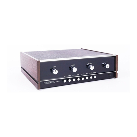
The Model AA-151 Stereo Amplifier has three
basic sections; acommon power supply, the
left channel preamplifier and amplifier, and the
right channel preamplifier and amplifier.
The left and right channel preamplifier and
amplifier circuits are identical, therefore, only
the left channel and power supply circuits will
be discussed. For the purpose of this description,
assume that the SOURCE switch is in the MAG.
PHONO position and that the MODE selector
switch is in the LEFT AMPposition. We suggest
that you frequently refer to the Schematic and
Block Diagrams.
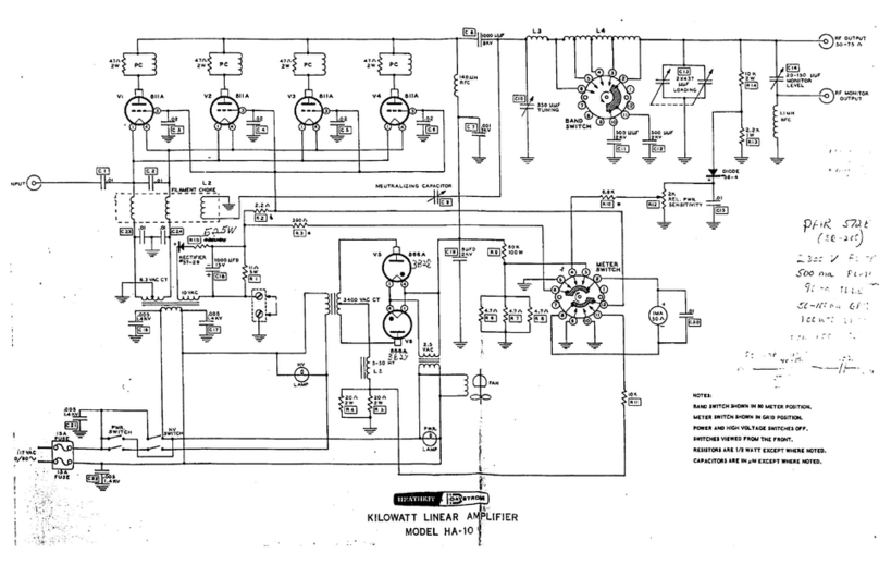
The audio signal presented to the MAG. PHONO
input is applied directly to the grid of tube VIA.
VIA is ahigh-gain, low-noise preamplifier stage.
The amplified signal is coupled from the plate
of VIA through capacitor C5 to the grid of VI B.
Resistors R9 and RIO, along with capacitors
C3, C4 and C6, provide RIAA equalization for
magnetic phono cartridges. VI Bis also ahigh-
gain preamplifier. The amplified signal from its
plate is coupled by capacitor C8 and the VOL-
UME control to the grid of V3.
V3 further increases the amplitude of the sig-
nal. The amplified signal from V3 is fed through
capacitor Cll to the packaged electronic tone
control network. This network consisting of sev-
eral resistors and capacitors, encapsulated in
an insulating material, operate in conjunction
with R20 and R23 to perform the BASS and
TREBLE control functions. The output signal of
the tone control network is applied through the
MODE switch to the grid of V6A.
The signal is again amplified by V6A and is
applied to the grid of V6B, the phase inverter
V6B does not amplify the signal, but applies
the signal in proper phase, to each tube (V7
and V8) in the push-pull amplifier output stage.
The signal from the push-pull output stage is
coupled through audio output transformer T1
to the left channel speaker system.
The power supply uses a5AR4 tube as afull-
wave rectifier. The filter network, consisting
of capacitors C25, C24, C23, and C22, and re-
sistors R36, R35, and R34, removes the 120
cycle ripple from the B+ voltage.

