Page 5
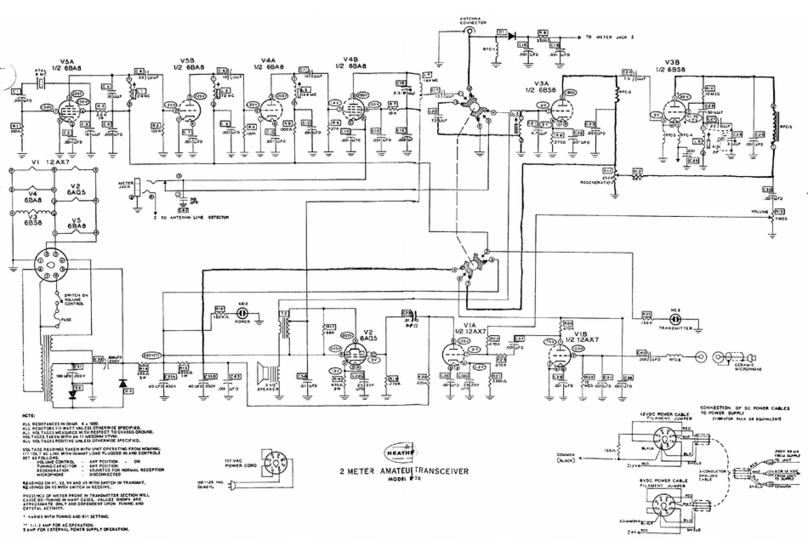
If the metering plug is inserted all the way
into the jack, the meter will read final ampli-
fier cathode current, typically in the order of
20-25 ma. The meter plug must be withdrawn
from this position for normal operation once
proper tuneup has been accomplished. The
meter plug in this fully inserted position over-
rides the normal functioning of the transmit -
receive switch and allows final amplifier plate
current to flow regardless of switch position.
With a key plug inserted all the way in the meter
jack, the transmitter may be used on CW if
desired, although considerable "back wave" may
result due to the fact that previous transmitter
stages are running constantly.
For phone operation, modulation is accomplished
by causing the plate and screen voltage source
for V4B to vary at the audio frequency rate
determined by the signal being passed through
the combination modulation -output transfor-
mer (see AUDIO SECTION description).
RECEIVER SECTION
The incoming signal received by the antenna
and arriving at the antenna connector via the
transmission line is supplied to an impedance
matching tap on coil L5, through capacitor C20.
The resultant signal appearing across the broad-
ly tuned circuit consisting of L5 and C21 is fed
to the input of the RF amplifier stage V3A.
The output circuit of the RF amplifier is "im-
pedance coupled" to the cathode circuit of the
superregenerative detector V3B through capac-
itor C24. This arrangement provides consider-
able gain in the RF stage, which does not re-
quire neutralization as the feed point in the
detector circuit is relatively low impedance.
This means of coupling these two stages elimi-
nates the most trying problem in most super-
regenerative detectors in that a condition re-
ferred to as "suck -out" can occur where a
tuned circuit is not properly isolated from the
detector. In other instances where a tuned cir-
cuit (it may be a coil and capacitor combin-
ation or reflected antenna tuning) is closely
coupled, the detector will drop out of oscillation
as detector tuning passes the resonant fre-
quency of the interfering tuned circuit. In
addition to solving the above problem and pro-
viding gain, the RF amplifier also isolates the
antenna from the oscillating detector, mini-
mizing re -radiation from the detector into
the antenna.
The type of detector used is one which pro-
vides the most sensitivity for the number of
components required and is superregenerative.
In a straight regenerative detector, consider-
able sensitivity is achieved by adjusting the
signal feedback of the detector for a near
oscillating condition. In the regenerative cir-
cuit, the more feedback that can be employed
with stable operation short of the detector
actually going into oscillation, the greater will
be the gain.
The superregenerative detector employed here
carries the regenerative principle one step
further in that the detector actually goes in
and out of oscillation at a controlled rate.
In doing such, the detector periodically passes
through the point of maximum gain (just prior
to oscillation) and therefore provides optimum
gain from its circuit. This periodic rate, re-
ferred to as the "quench" frequency, is con-
trolled by the value of RFC5, and associated
components, and is in the vicinity of 20,000
cycles per second; therefore, the quench fre-
quency is inaudible. The detector circuit is
essentially a Colpitts type of oscillator circuit
in which interelectrode tube and stray capac-
ities form the normal feedback path. The detec-
tor cathode and heater are placed above RF
ground by RF chokes RFC3 and RFC4. The
plate circuit is bypassed for RF by C29.
The rear apron mounted 250 Ka linear po-
tentiometer Rh is adjusted for maximum sen-
sitivity by setting the value of B+ voltage at the
detector plate. The receiver configuration is
one of very good sensitivity. Three micro-
volts input will produce near complete quiet-
ing with usable signals extending down to 1/2
microvolt.
AUDIO SECTION
The detected audio signal passes through C30
to the 1 megohm volume control R13. Signal
flow proceeds through the audio mixing resistor
R22 to the grid of the audio driver VIA which is
coupled to the power output stage V2 by capac-
itor C35. The combination modulation -output
transformer T2 provides proper impedance
matching to the speaker with the unit operating
as a receiver. With the transmit -receive switch
in the receive position, no loading of the audio
output occurs at the primary modulation tap
because the cathode circuit of the transmitter
final amplifier is open. During receive, tubes
V5, V4 and section V1B are inoperative.
