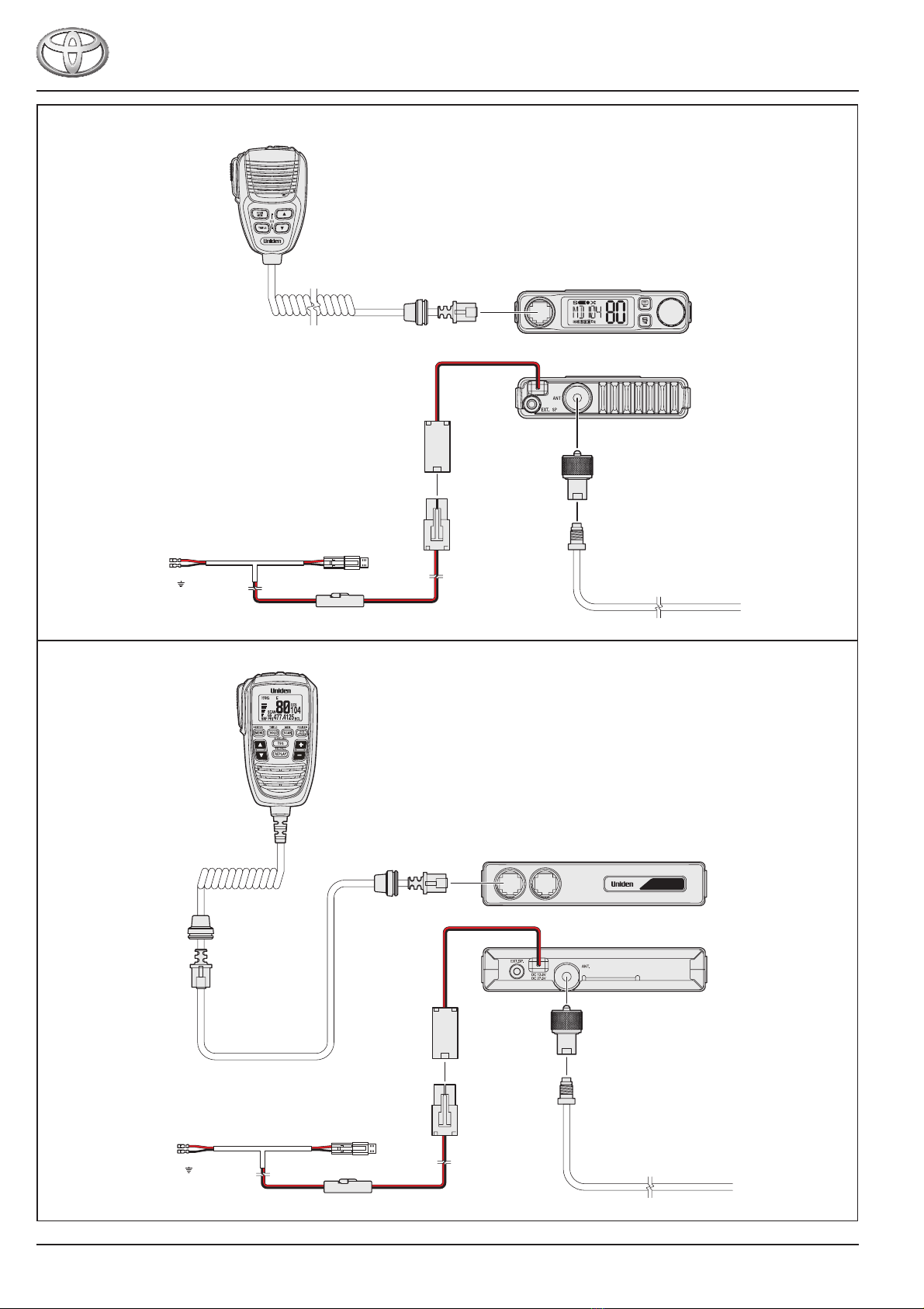
Fitting Instructions
UH9000S / UH9060S / UH9080S
Page 3 of 14
WARNING
This vehicle is equipped with Supplemental Restraint System (SRS) airbags and seatbelt pretensioners.
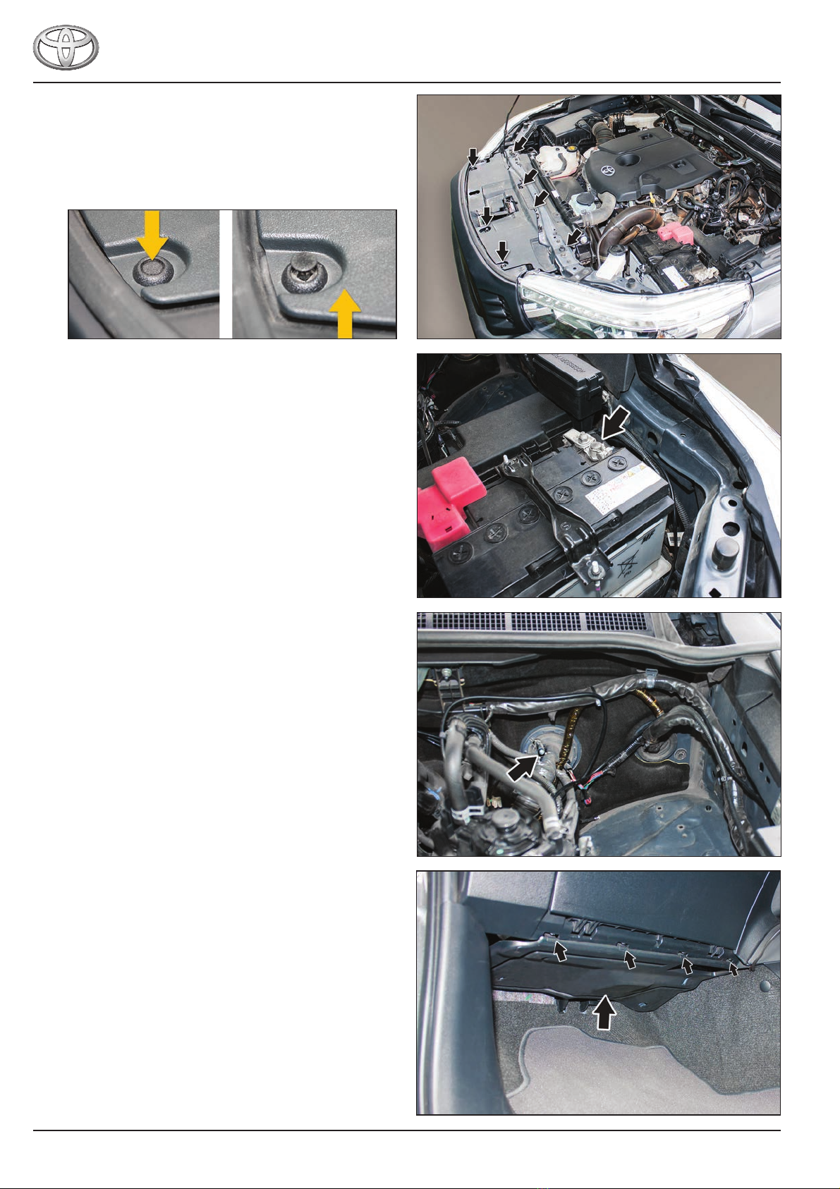
Before starting work, wait at least 90 seconds after the ignition switch is turned off and the negative (-) battery terminal
cable is disconnected.
SRS parts are equipped with a backup power source. If work is started within 90 seconds of turning the ignition switch off
and disconnecting the negative (-) battery terminal cable, SRS parts may deploy possibly causing serious injuries.
WARNING
Do not install any parts in a location that may interfere with the operation and deployment of the SRS airbags or seatbelt
pretensioners, including driver, front passenger and knee SRS airbags if tted. Doing so may result in serious injury or
death.
PREPARATION
• Follow all standard workshop and occupational health and safety practices during the installation process.
• Check and note any existing marks or damage to the vehicle.
• Before starting the installation thoroughly read through these installation instructions then follow the tting sequence as described.
• Check that the UHF CB transceiver kit is complete.
• Take all possible precautions to avoid damaging the vehicle’s interior and exterior during the installation. Use protective tape on
parts and tools where necessary.
• To avoid damage to the wiring harness and antenna cable, avoid contact with sharp edges. Cable tie securely every 200 mm.
• Ensure all removed parts are re-tted correctly.
SPECIAL TOOLS
• Trim removal tools
• Protective tape
• Lead wire
PARTS LIST - UHF CB TRANSCEIVER KITS
Model UHF CB Transceiver Kit Fitting Kit Part Number
HILUX
UH9000S
UNIFK001UH9060S
UH9080S
PARTS LIST - ANTENNA
Model Antenna Part Number Description
HILUX
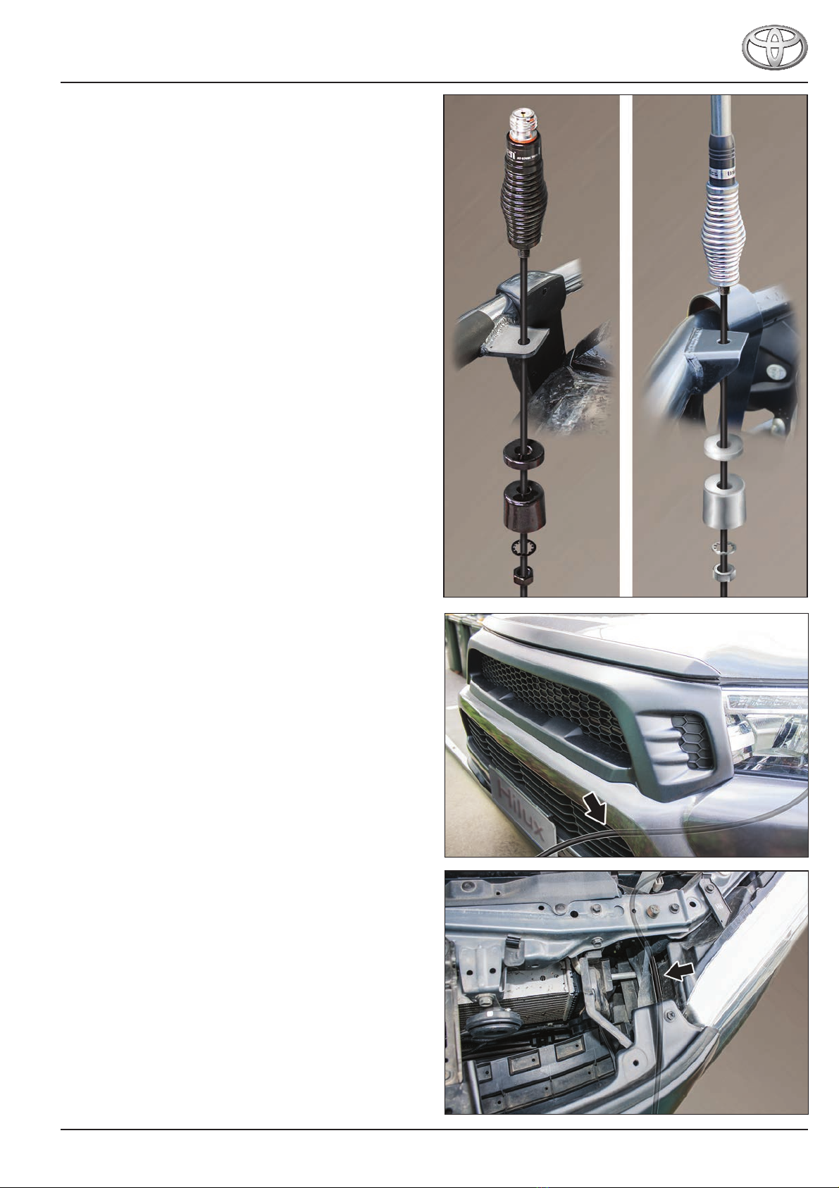
AT970BKTWIN Antenna Dual Whip Black
AT970WTWIN Antenna Dual Whip White
AT970BK Antenna 1200mm Black
AT970W Antenna 1200mm White
AT890BK Antenna 1000mm Black
AT890W Antenna 1000mm White
AT880TWIN Antenna Dual Whip Stainless Steel