HeatLink 11500 User manual
Serial Number
Hydraulic
Pressure
Check
HE 152
HE.15274
HE.12488_B © 05/2013 R&D-2
Slim-line Power Press Tool
11500
HeatLink Group Inc.
+1 (800) 661-5332
www.heatlinkgroup.com
L611500 Rev. B

Instruction Manual Pressing Tool
I
pic. 1
HE 152
HE.15274
Legend p.2
Legend pp.3-4
L611500 Rev. B © 05/2013
11500
15 min.
20 sec/5Hz
page VIII
RESTART
5 Makita BL1815
optionally:
Makita BL1830
9
8
14
7
23
6
Instruction Manual Pressing Tool
II
pic. 3
1
2
3
4
5
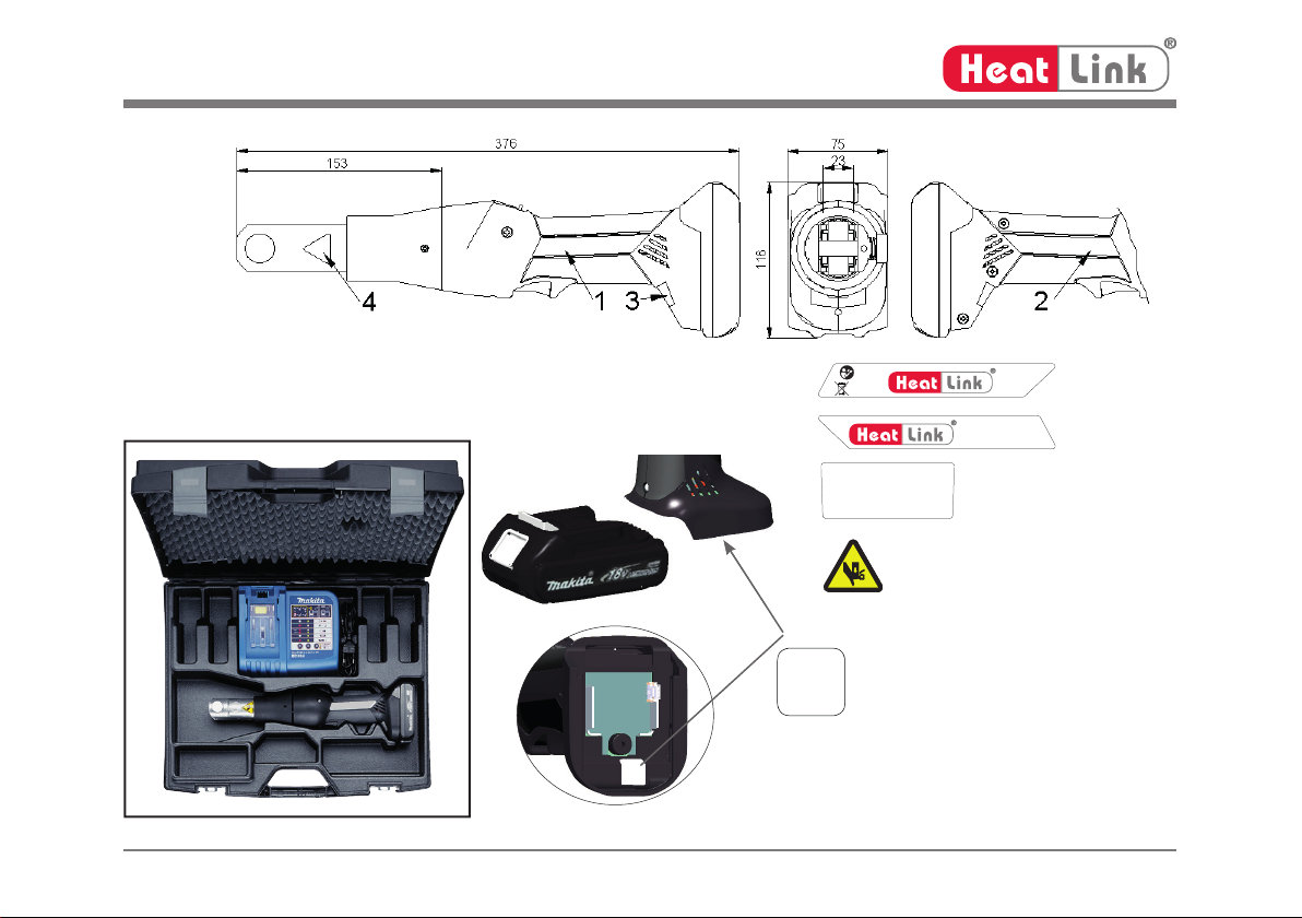
304711 batch# e.g. 304711
CV datecode e.g. C = 2009; V = July.
142 consecutive# e.g. „142“ = tool # 142
5
pic. 2
11500
Voltage: 18V DC
Thrust: 15 kN
HE.15275
HE.15274
L611500 Rev. B © 05/2013
11500
HE.12486
HeatLink Group Inc.
Head Office
4603E - 13th Street NE
Calgary, AB T2E 6M3-Canada
Instruction Manual Pressing Tool
III
pic. 4 pic. 5
pic. 6 pic. 7 pic. 8
pic. 9 pic. 10
pic. 11
Li-ion
pic. 12
®
#884676B996
#884598C990
pic. 13
L611500 Rev. B © 05/2013
11500
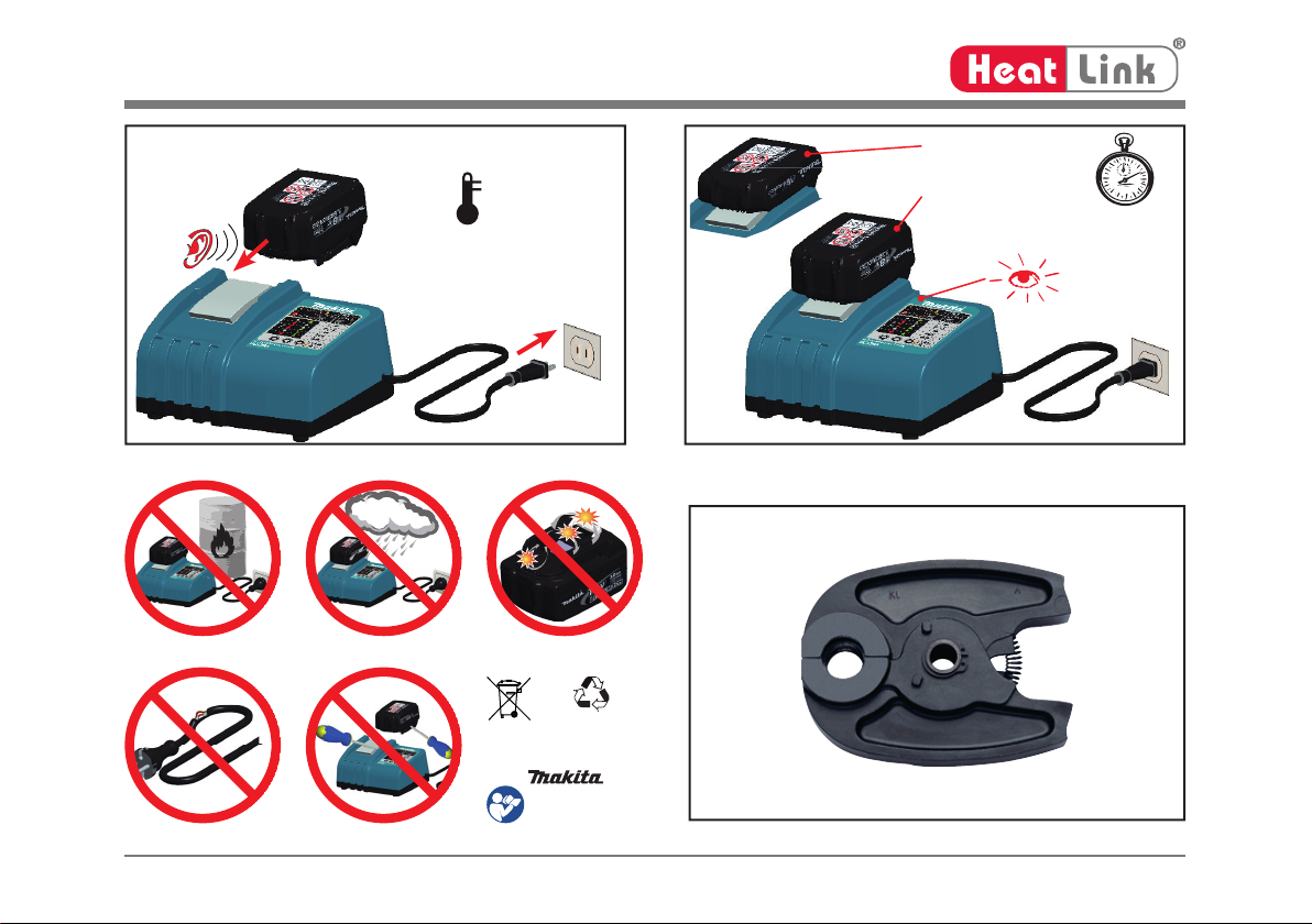
Makita 15 min.
BL1815
optional:
Makita 22 min.
BL1830
CLICK
50 - 104°F
(10 - 40°C)
Instruction Manual Pressing Tool
IV
pic. 14 pic.15
1. 2.
350°
pic. 16 pic. 17
45°
1.
2.
OIL
1.
2.
HE.15274
Folie: weiss Druck: farbig
linke Seite, erstellt 10 0
HE.15274
L611500 Rev. B © 05/2013
11500
Instruction Manual Pressing Tool
V
pic. 18 pic. 19
CLICK
1.
2.
on / off
PRESS
PRESS
L611500 Rev. B © 05/2013
11500

Instruction Manual Pressing Tool
VIL611500 Rev. B © 05/2013
11500
Pure
®
Link
Link
Plus
P
u
r
e
®
Link
Link
P
l
u
s
P
u
r
e
®
Link
Link
Pl
u
s
P
ure
®
Link
Link
Plus
Pu
r
e
®
Link
Link
P
l
u
s
Pu
r
e
®
Link
Link
P
l
u
s
Preparation
1. Inspect all components for debris, obstructions, and/or
damage prior to installation.
2.Cut the PEX tubing to length, ensuring a square cut - an
irregular cut may result in a failed connection. For larger
diameter PEX an ABS cutter is recommended.
3. Slide the stainless steel sleeve over the tubing until it is
properly seated.
4. Push the tubing and sleeve onto the fitting or Multiport tee
until it bottoms out on the shoulder.
5. Use the sight hole in the sleeve to verify proper seating
of PEX tubing.
6. Make press as instructions below for 1»2" to 1 1»2".
1»2" to 1 1»2" Press Instructions; Auto Press
{Never press with empty jaws as this will damage the jaws.
{Regularly check tool jaws and sleeve for any abnormalities that
could be an indication of a damaged tool.
{If the Stainless Steel Sleeve is damaged or pressed incorrectly,
ERWKWKH¿WWLQJDQGWKHVOHHYHPXVWEHUHSODFHG
{Never re-use stainless steel press sleeves.
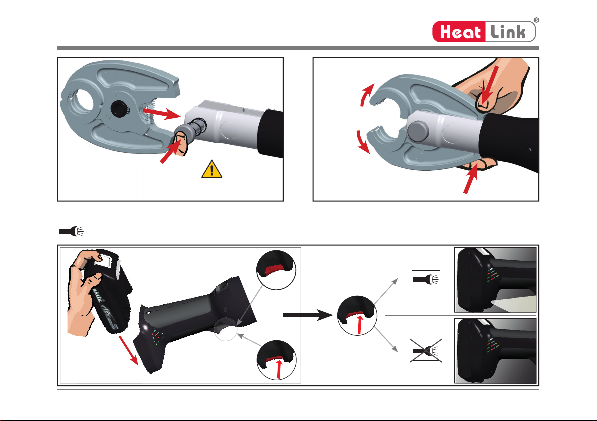
1. Open the jaws and position squarely around the sleeve, then
DOORZWKHMDZVWR¿UPO\JUDVSWKHVOHHYH
LinkPure
®
Link Plus

Instruction Manual Pressing Tool
VIIL611500 Rev. B © 05/2013
11500
2. Squeeze the trigger until the press is complete.
Note: if the red LED flashes or there an audible beep,
consult “Tab. 1.”
3. Open the jaws and remove the tool from the sleeve.
4. Inspect the connection to ensure the tubing is still
properly seated (only PEX is visible in sleeve sight
hole), and the press has been properly formed onto the
sleeve (see diagram for guideline).
Tool jaws imprint "HL" on the sleeve.
An improperly positioned tool may result in a poor
press and a damaged fitting.
Pu
P
u
Pu
Sight
Hole
Improperly
positioned
jaws
PEX
improperly
seated in
sleeve
Pinched Stainless Steel Sleeves
If the stainless steel sleeves are being pinched, the tool jaws
are worn out or damaged and must be replaced.
Example Presses
1»2"3»4"1"
11»4"1
1»2"
Instruction Manual Pressing Tool
VIII
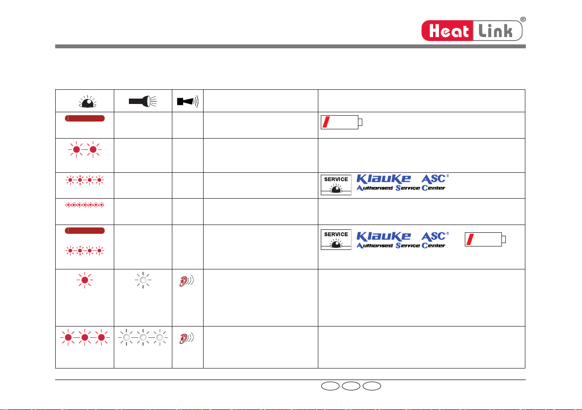
Tab. 1 Visual and Audio Indicator Meanings
Explication des signales acoustiques et visuels
Descripción de las indicaciones del diodo luminoso
When / Quand / cuándo Why / Pourquoi / ¿por qué?
20 sec
after working cycle
après opération de travail
Después del proceso de trabajo
2 x
after inserting the battery
après mise en place de
l’accumulateur
Después de insertar la batería
Self check
autocontrôle
Auto-test
20 sec/2Hz
after working cycle
après opération de travail
Después del proceso de trabajo
20 sec/5Hz
while exceeding the temp. limit
pendant surchauff e
en caso de temperatura excesiva
Unit too hot
outil surchauff é
Herramienta demasiado caliente
20 sec
20 sec/2Hz
after working cycle
après opération de travail
Después del proceso de trabajo
+
1 x 1 x
after working cycle
après opération de travail
Después del proceso de trabajo
Error: the required pressure has not been reached. The operator
has interrupted the pressing cycle manually while the motor was
not running.
Erreur: Pression necessaire pas atteinte. Il s‘agît d‘une interrupti-
on manuelle de la sertissage au moteur arrêté.
Error: No se ha alcanzado la presión necesaria o el operador ha
interrumpido el ciclo a mano mientras el motor ha parado.
3 x 3 x
after working cycle
après opération de travail
Después del proceso de trabajo
Serious Error: The pressure has not been reached while the motor
was running.
Erreur grave: Pression pas atteinte au moteur courant.
Error grave: No se ha alcanzado presión mientras el motor estaba
en marcha
US F Sp
L611500 Rev. B © 05/2013
11500
1
US
Instruction Manual Pressing Tool
authorised
copy
L611500 Rev. B © 05/2013
11500
Index
1. Introduction
2. Warranty
3. Description of the electro-hydraulic pressing tool
3.1 Description of the components
3.2 Features
3.3 Visual and Audio Indicator Meanings
4. Operating Instructions
4.1 Operation of the tool
4.2 Explanation of the application range
4.3 Service and Maintenance
5. Troubleshooting
6. Technical data
7. Decommissioning/Disposal
Symbols
Safety Warnings
Please do not disregard to avoid injuries and environmental damage
Application Warnings
Please do not disregard to avoid damaging the tool.
1. Introduction
Before using the tool please read the instruction manual carefully.
Use this tool exclusively for its determined use and follow all applicable safety instructions. This instruction manual
should accompany the tool for its entire life span.
The owner has to: • guarantee the availability of the instruction manual for the user and
• make sure, that the user has read and understood the instruction manual.

2
US
Instruction Manual Pressing Tool
authorised
copy
L611500 Rev. B © 05/2013
11500
2. Warranty
If the tool is operated according to its intended use and the regular maintenance services are observed our war-
ranty is 24 months from the time of delivery. Worn-out parts resulting from regular use are excluded. We reserve
the right to rework the tool in case of a valid warranty claim.
3. Description of the battery operated electro-hydraulic pressing tool
3.1 Description of the components
The hydraulic tool is a hand operated tool and consists of the following components:
Table 2 (see page I, pic.1)
Pos. Description Function
1 Pressing head Working unit to accommodate the pressing jaws
2 Retract slide Slide to open the pressing jaws in case of an error or emergency
3 LED (red) Indicator for battery charge, service Intervals and faults
4 Battery lock Slide to unlock the battery
5 Battery Rechargeable Li-Ion battery 18V
6LED (white) to illuminate the working area
7 Trigger Actuator to start the pressing cycle
8 Jaws Pressing jaws
9 Locking pin Pin with special lock to open/close the pressing head

3
US
Instruction Manual Pressing Tool
authorised
copy
L611500 Rev. B © 05/2013
11500
3.2 Features
Safety features:
The unit is equipped with a special brake which instantly stops the forward motion of the piston/dies when the trigger
is released.
A white LED illuminates the working space after activating the trigger. It automatically switches off 10 sec. after relea-
sing the trigger. This feature can be deactivated (see page V).
Hydraulic Pressure Check, HPC for short, monitors the oil pressure in the tool’s oil circuit, hence ensuring a conti-
nuous, consistent press quality.
During each pressing cycle, the achieved pressing pressure is determined by a pressure sensor and compared to the
required minimum value. An audible warning signal sounds if the achieved pressure diff ers from the specified working
pressure. The user will know immediately that the fi tting must be checked and repressed or replaced as required.
Functional features:
The hydraulic unit incorporates an automatic retraction which returns the piston into its starting position when the
maximum operating pressure is reached.
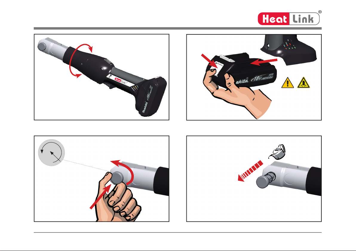
A manual retraction allows the user to return the piston into the starting position in case of an incorrect press.
The pressing head can be smoothly turned by 350° around the longitudinal axis in order to gain better access to tight
corners and other diffi cult working areas.
The unit is equipped with a microprocessor (page I, pic. 1.3) which shuts off the motor automatically after the press
is completed, indicates service intervals, checks battery capacity and does a trouble check e.g. informing the user
through audible and visual warning signals about the kind of error.
Power saving function through motor switch-off .
The ergonomically formed compact housing has two important features. The non-slip rubber coated grip area to-
gether with a balanced center of gravity allows fatigue-free working.
All tool functions can be controlled by one trigger. This results in an easy handling and a better grip compared to a
two button operation.
4
US
Instruction Manual Pressing Tool
authorised
copy
L611500 Rev. B © 05/2013
11500
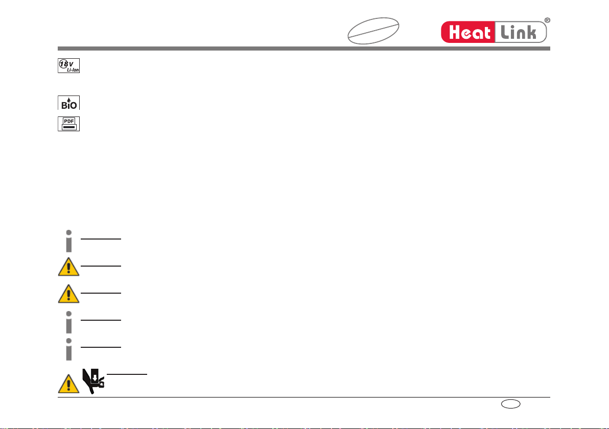
Li-Ion batteries have neither a memory eff ect nor self-discharge. Even after long periods of non-operation the tool
is always ready to operate. In addition, they have a lower power weight ratio with 50% more capacity and shorter
charging cycles compared to NiMH batteries.
The oil used in our tool is rapidly bio-degradable and non-hazardous to water, and has been received “The Blue
Angel” ecolabel. The oil is suitable for low temperatures and has excellent lubrication characteristics.
At the end of a job a print-out via a USB adapter (not included) can be generated documenting the proper function
of the tool.
3.3 Visual and Audio Indicator Meanings
See page VIII, tab. 1
4. Operating Instructions
4.1 Operation of the tool
The pressing cycle is started by squeezing the trigger (page 1, pic. 1.7). The pressing cycle is characterized by the closing
motion of the jaws. Due to the linear movement of the rollers on the piston the jaws close scissors like.
Attention
The pressing cycle must be completed and the jaws closed to ensure a permanent leak free connection.
Attention
The pressing process can be interrupted at any moment by releasing the trigger.
Attention
This tool is intended for use with HeatLink®PEX tubing, fittings, and stainless steel press sleeves.
Attention
The user has to check by visual means whether the pressing jaws are completely closed.
Attention
If a pressing cycle has been interrupted the fitting has to be either replaced or pressed a second time.
Attention
Do not operate the tool without jaws.
5
US
Instruction Manual Pressing Tool
authorised
copy
L611500 Rev. B © 05/2013
11500
Attention
For your own safety please observe all local safety regulations.
The user needs to make sure that the pressing jaws are completely closed and that there are no foreign objects (e.g.
plaster or stone fragments) between the pressing jaws.
4.2 Application
This tool is meant for use with HeatLink® stainless steel press sleeves, PEX tubing, and fi ttings.
The unit is not to be restrained in a vise. It is not allowed to use the tool in a stationary application.
The tool is not designed for continuous use. After series of approximately 50 completed presses, let the tool cool
down for 15 min.
Attention
Overly intensive use can cause heat damage to the tool
Attention
During the operation of the built-in electric motor, sparks can occur, which might ignite highly inflammable
or explosive liquids and materials.
Attention
Electric tools must not be operated in pouring rain or under water.
4.3 Service and Maintenance
The reliable operation of the tool is dependent on proper handling and service. To ensure proper presses, this tool
must be mainted and serviced regularly as follows:
1. The electric-hydraulic pressing unit must be cleaned and dried after each use before stored.
2. In order to guarantee reliable operation, the pressing tool should be returned to the manufacturer or one of our Au-
thorized Service Centers (ASCs) after the red LED indicates Service (after 10,000 pressing cycles) or once every
year whichever occurs fi rst.
3. The nuts and bolts, the rollers and their guides as well as the moveable parts of the pressing jaw must be
lightly oiled on a regular basis.
6
US
Instruction Manual Pressing Tool
authorised
copy
L611500 Rev. B © 05/2013
11500
4. Perform and inspect test presses or have the tool manufacturer check the tool and pressing jaws regularly to en-
sure proper function.
5. Keep the pressing jaws clean. Remove dirt with a brush.
In order to avoid possible malfunctions we off er you a manufacturer service consisting (see ASC) of disassembly,
cleaning, exchange of possibly worn out parts assembly and fi nal inspection. Only a clean and properly functioning
press tool can ensure a leak free connection.
The tool has no user serviceable parts. Only the pressing jaws (page I, pic. 1.8; page III, pic. 13) and battery can
be changed by the user.
Attention
Do not damage the seals of the tool. If the seals are damaged the warranty is null and void.
5. Troubleshooting
a.) Constant fl ashing/indicating of the red LED (page I, pic 1.3) or an audible warning signal.
see table 1. If the issue cannot be resolved return the tool to the nearest Authorized Service Center (see
inside back cover).
b.) The tool is leaking oil.
Return the unit to the manufacturer. Do not open it and damage the seal of the tool.
c.) The red LED fl ashes 3x and simultaneously 3 acoustic warning signals occur (see table 1).
Serious fault! If this fault occurs repeatedly, return the unit to an Authorized Service Center (ASC). Do not
open it and damage the seal of the tool.
In case of a one time occurrence the fi tting has to be replaced or pressed a second time.
7
US
Instruction Manual Pressing Tool
authorised
copy
L611500 Rev. B © 05/2013
11500
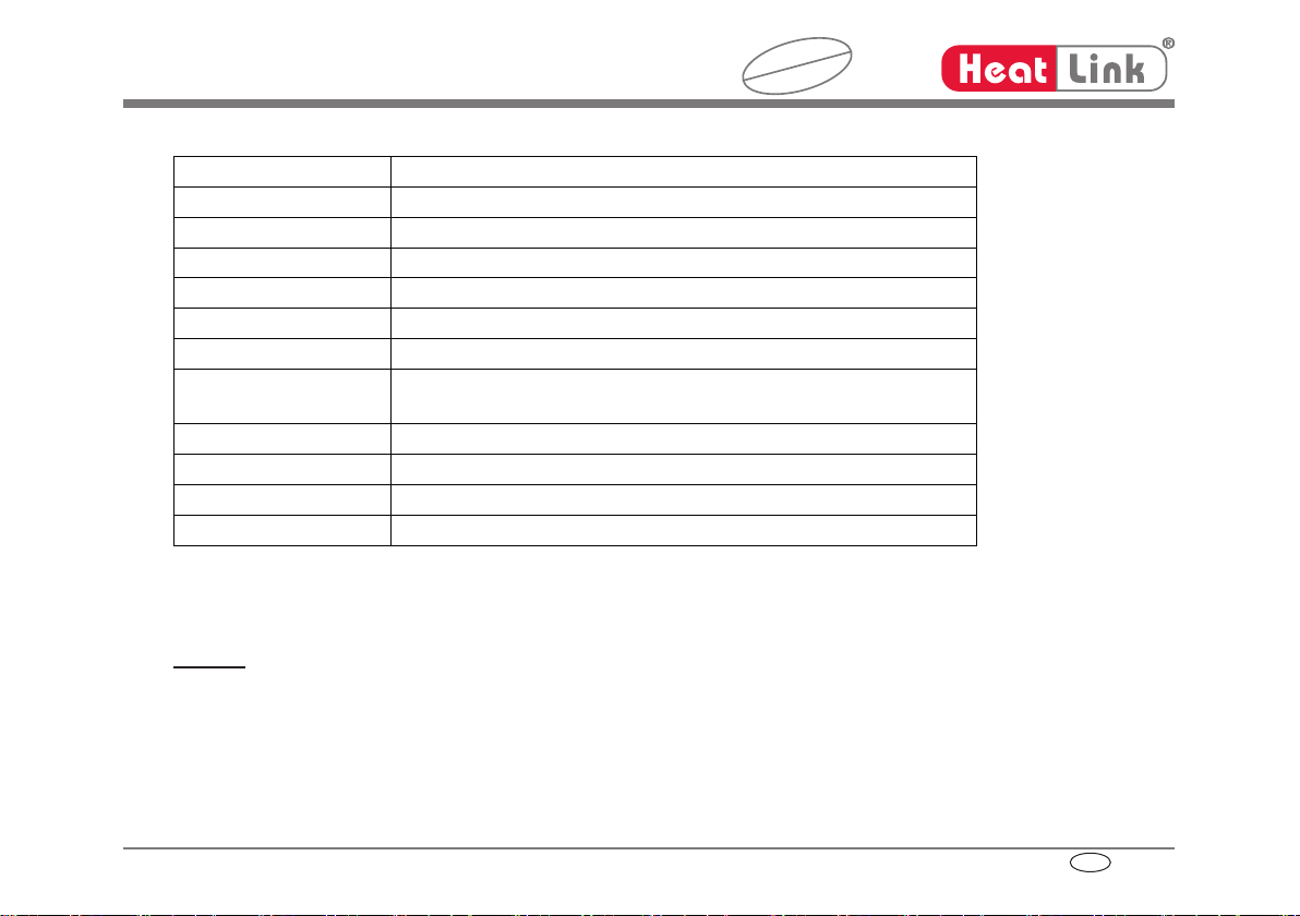
6. Technical Data
Type 11500
Weight incl. battery: 3.74 lb (1.7 kg)
Pressing time: 3-4 s
Thrust force (linear): 15 kN min.
Battery voltage: 18 V
Battery capacity: 1.3 Ah Li-Ion (Makita BL1815) or 3.0 Ah Li-Ion (Makita BL1830)
Battery charging time: 15 min. (Makita BL1815) or 22 min. (Makita BL1830)
Presses/charge: approx. 150 presses (1/2”) (Makita BL1815)
approx. 300 presses (1/2”) (Makita BL1830)
Ambient temperature: 14°F to 104°F (-10°C to +40°C)
Hydraulic oil: Rivolta S.B.H. 11
Sound level: < 70 dB (A) at a distance of 3.3 ft (1 m)
Vibrations: < 2.5 m/s²
7. Decommissioning/Disposal
The tool and battery must be disposed of in accordance with local guidelines and regulations.
Remark
This instruction manual can be ordered free of charge. The Part No. is L611500 (HE.12488).
1
F
Mode d´emploi sertisseuse
copy
L611500 Rev. B © 05/2013
11500
Sommaire
1. Introduction
2. Garantie
3. Description de outillage hydraulique
3.1 Description des composants
3.2 Caractéristiques
3.3 Explication des signales acoustiques et visuels
4. Consignes pour un usage conforme
4.1 Utilisation de l‘appareil
4.2 Application
4.3 Service et Maintenance
5. Marche à suivre en cas de panne de la outillage
6. Caractéristiques techniques
7. Mise hors service / Mise au rebut
Symboles
Instructions techniques de sécurité
à respecter impérativement, pour la sécurité des personnes et la protection de l‘environnement.
Instructions techniques d‘utilisation
à respecter impérativement, pour éviter des dommages à l‘appareil.
1. Introduction
Lire attentivement le mode d‘emploi avant la mise en service de votre outillage.
N‘utilisez cet appareil qu‘exclusivement pour l‘usage prévu, en respectant les instructions relatives à la sécurité et à
la prévention des accidents du travail.
L‘exploitant doit • mettre le mode d‘emploi à la disposition de l‘utilisateur et
• s‘assurer que celui-ci ait lu et bien compris son contenu.

2
F
Mode d´emploi sertisseuse
copy
L611500 Rev. B © 05/2013
11500
2. Garantie
La garantie s’élève à 24 mois date de la livraison à condition d’une utilisation de l’outil exclusivement pour son
usage déterminé et d’observation des intervalles des maintenance. Sauf pièces de rechanges qui résultent d’un
usage déterminé. Nous réservons le droit de récupérer le produit.
3. Description de outillage hydraulique
3.1 Description des composants
L’ outillage électro-hydraulique est un appareil conduit manuel qui se compose des éléments suivants:
Tabl. 2 (cf. page I, fig. 1)
Pos. Désignation Fonction
1Tête de sertissage Unité de travail pour le logement des mâchoires de sertissage
2Commutateur de retour Commutateur glissant d‘ouverture des mâchoires de sertissage
en cas d‘anomalie ou d‘arrêt d‘urgence.
3Affi cheur LED (rouge) Indication capacité d’accumulateur, indication Service et erreur d’outil
4Déblocage de l‘accumulateur Commutateur glissant de déblocage de l‘accumulateur
5Accumulateur Accumulateur rechargeable au Li-Ion 18V
6LED (blanche) Pour l’éclairage du local de travail
7Commutateur de marche Déclenchement du sertissage
8Mâchoires de sertissage Mâchoires de sertissage (dépendent du système)
9Boulons de verrouillage Dispositif de verrouillage pour l‘ouverture/fermeture de la tête.
3
F
Mode d´emploi sertisseuse
copy
L611500 Rev. B © 05/2013
11500
3.2 Caractéristiques
Caractéristiques de sécurité
L‘outillage est équipé d‘un dispositif d‘arrêt immédiat qui stoppe instantanément l‘avance dès que le bouton de mar-
che/d´arrêt est lâché.
LED blanche illumine le local de travail en actionnant le commutateur de service et s’éteint après 10 s. Cette fonction
peut être éliminée.
La fonction Hydraulic Pressure Check, abrégée HPC contrôle la pression d’huile directement dans le circuit d’huile
des outils et assure ainsi une qualité uniforme et constante des sertissages.
À chaque cycle de sertissage, la pression atteinte est déterminée au moyen d’un capteur de pression, puis comparée
à la valeur minimale requise. Un signal acoustique et optique paraît lorsque des diff érences par rapport à la pression
de travail déterminée se produisent.
Caractéristiques de fonction
L‘outillage possède une fonction de retour automatique, qui ramène automatiquement les galets d‘entrainement en
position initiale après que la sertisseuse ait atteint sa pression maxi de fonctionnement.
Un retour manuel permet à l’utilisateur de retourner le piston à la position initiale coupage.
La tête peut être tourné de 350° en continu autour de son axe de rotation. Ceci permet le coupage à des endroits
diffi cilement accessibles.
L’outil est équipée d’un système électronique donnant informations importantes sur l’état de la machine, le résultat
de coupage et la capacité de l’accumulateur. L’indication s’eff ectue par diode luminescente ou par un signal acous-
tique.
Fonction d’économie d’énergie grâce à l‘arrêt automatique du moteur en fi n de cycle de sertissage.
Le corps en plastique bi-matière avec insert souple contribue à une sensation de prise agréable et sûre. La position
optimisée du centre de gravité permet en complément un travail durable et sans fatigue.
Toutes fonctions de l’outil s’eff ectuent par moyen d’une commande à bouton unique pour une maniement aisée et
un meilleur appui.
Accus lithium-ions 18V puissants avec une capacité complémentaire de 50% et des délais de charge extrêmement
courts. Ces accumulateurs n’ont pas d’eff et mémoire et auto-décharge électrique.
4
F
Mode d´emploi sertisseuse
copy
L611500 Rev. B © 05/2013
11500
Cet outil travaille avec huiles hydrauliques synthétiques. Ces huiles sont facilement biodégradables et ne présentent
aucun danger pour l’eau.
Fonction d’évaluation par interface optique et adaptateur USB. (Équipement spéciale).
3.3 Explication des signales acoustiques et visuels
Voir page IX, tableau 1
4. Consignes pour un usage conforme
4.1 Utilisation de l‘appareil
Un processus de sertissage se déclenche en actionnant le commutateur de service (page I, fi gure 1.7).
La fermeture des mâchoires signale le commencement du processus de sertissage. Les mâchoires de sertissage se
ferment en forme de ciseaux au moyen des rouleaux d‘entraînement situés sur la barre de piston.
Attention
Effectuer un contrôle visuel à la fin du processus de sertissage pour vérifier si les mâchoires de sertissage
sont entièrement fermées.
Attention
Le cycle de sertissage peut être interrompu à tout instant en relachant la pression exercée sur le bouton de
commande.
Attention
Cet outil est prevu pour utilization avec HeatLink® PEX tube, raccords, et bagues à sertir inoxidables.
Attention
A la fin du cycle de sertissage, il est nécessaire d‘effectuer en plus un contrôle visuel, pour vérifier que les
mâchoires soient bien complètement fermées.
Attention
Les raccords pour lesquels le cycle de sertissage n‘a pas été complètement terminé doivent être démontés,
ou faire l‘objet d‘un nouveau sertissage complet.
Table of contents
Languages:
Other HeatLink Power Tools manuals


