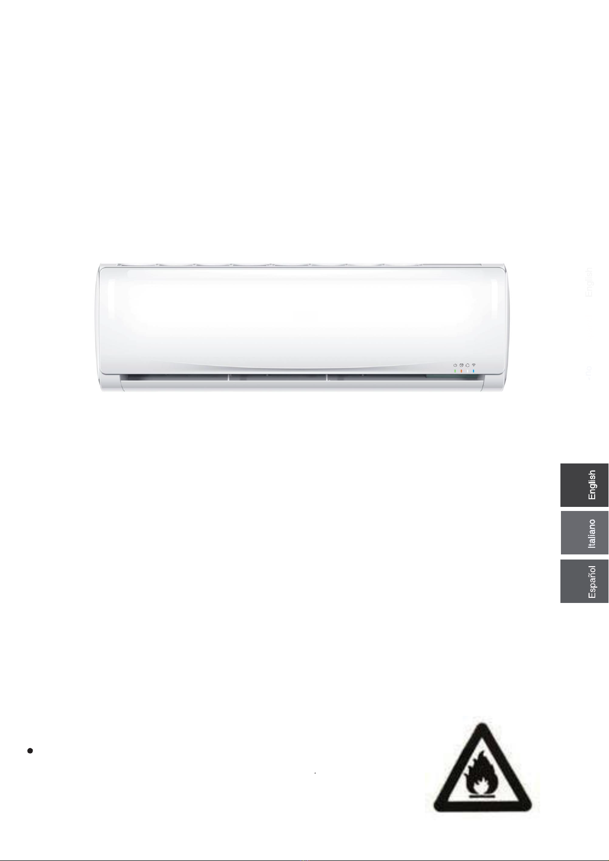
HEC HSU-09TK/R32(DB)-IN User manual
Please
●
read this operation manual before using the air conditioner.
Keep this operation manual for future reference
This appliance is filled with R32.
0010596337
HSU-09TK/R32(DB)-IN
HSU-12TK/R32(DB)-IN
HSU-18TK/R32(DB)-IN
HSU-24TK1/R32(DB)-IN
HSU-09TK/R32(DB)-INM
HSU-12TK/R32(DB)-INM
HSU-09TK1/R32(DB)-IN
HSU-12TK1/R32(DB)-IN
HSU-18TK1/R32(DB)-IN
HSU-09TK1/R32(DB)-INM
HSU-12TK1/R32(DB)-INM
SPLIT TYPE ROOM AIR CONDITIONER
OPERATION MANUAL
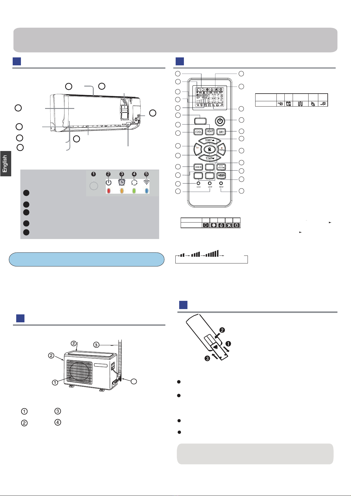
Outdoor Unit
●
Loading of the battery
1
2
3
4
●
Parts and Functions
Indoor Unit
OUTLET
INLET
CONNECTING PIPING AND ELECTRICAL WIRING
DRAIN HOSE
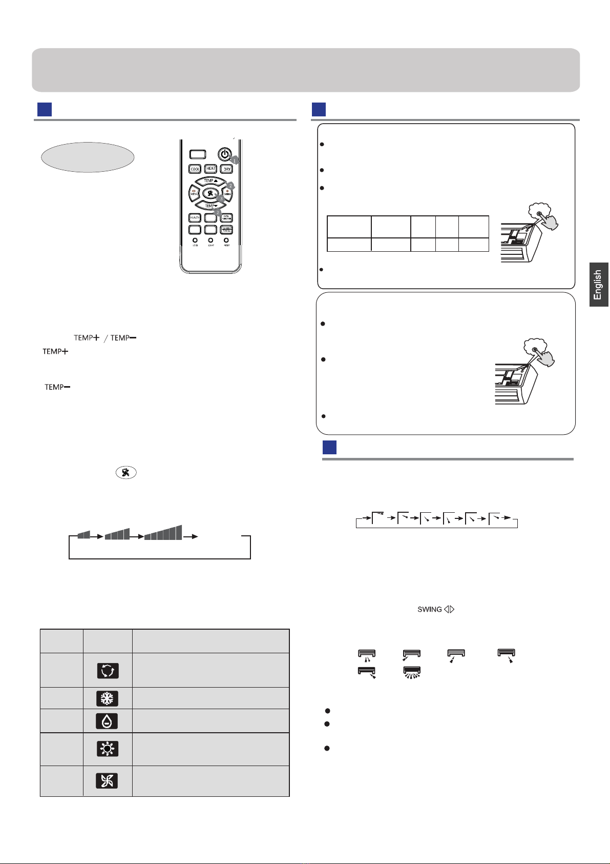
Remote controller
Remove the battery cover;
Load the batteries as illustrated.
2 R-03 batteries, resetting key
(cylinder);
Be sure that the loading
is in line with the" + "/"-";
Load the battery,then put on the cover again.
The distance between the signal transmission head and the rece-
iver hole should be within 7m without any obstacle as well.
When electronic-started type fluorescent lamp or change- over
wireless telephone is installed in the
ver is apt to be disturbed in receiving the signals,
so the distance to the indoor unit should be shorter.
type fluorescent lamp or
room, the recei
Note:
Full display or unclear display during operation indicates the
ries
●
have been used up. Please change batteries.
If the remote controller can't
●
run normally during operation, please
reload several minutes later.
batte
remove the batteries and
Please be subject to the actual produce purchased the
above picture is just from your reference
4
Hint:
Remove the batteries in case won't be in use for a long period. If
there is any display after taking-out, just press reset key.
Healthy function is not available for some units.
1. Mode display
2. Signal sending display
4. FAN SPEED display
5. LOCK display
6. TIMER OFF display
TIMER ON display
16. LOCK button
25. RESET button
When the remote controller appears
abnormal, use a sharp pointed
article to press this button to reset
22. TIME OFF/ON button
Control the lightening and extinguishing
of the indoor LED display board.
8.
9. TURBO button
11. COOL button
10. HEAT button
12. SWING LEFT/RIGHT button
13. FAN SPEED button
14. HEALTH button
15. SLEEP button
17. LIGHT button
18. POWER ON/OFF button
19. DRY button
20. TEMP button
21. SWING UP/DOWN button
23. EXTRA FUNCTION button
24.CANCEL/CONFIRM button
Function: Setting and cancel to the
timer and other additional functions.
3. SWING display
Operation mode AUTO FAN
COOL DRY
Remote controller
HEAT
LO MED HI AUTO
Display
circulated
the remote.
Additional functions display
1
2
3
4
5
9
10
11
12
13
14
15
16
17
8
22
23
24
25
19
20
21
18
7
6
Operation mode
Remote controller
QUIET TURBOSLEEP
Supplemented
electrical
heating HEALTH
Function: HEALT AIR FLOW ----
AUTO --- FAN
Display board
Actual inlet grille may vary from the one shown in the
manual according to the product purchased
(adjust left and
ow)
Vertical blade
right air fl
Air Purifying FilterInlet
(inside)
Emergency
Switch
Horizontal flap
(adjust up and down air flow
Don't adjust it manually)
Outlet
Inlet grille
6
5
2
1
4
3
6
4
2
1
5
3
(inside)
7
8
Anion generator
1
TURBO
SWING
SLEEP
TIME
ON
TIME
OFF
7. TEMP display
Display board
4
2
3
1
5
Operation mode indicator
(lights up when the compressor is on.)
Timer mode indicator
(Lights up whenTimer operation is selected.)
Power indicator
(Lights up when unit starts.)
WIFI(Optional)
Remote signal receiver
(A beeping sound is generated when a signal from remote controller isreceived.)
Operation
Air Flow Direction Adjustment
●
Press FAN button.
For each press button fan speed
follows:
Remote controller:
Press button
Every time the button is pressed, temp.setting
increase 1oC,if kept depressed, it will increase
rapidly
Every time the button is pressed, temp.setting
decrease 1oC,if kept depressed, it will
decrease rapidly
Select a desired temperature.
3.Fan function
2.Select temp.setting
Air conditioner is running under displayed fan speed.
●
When FAN is set to AUTO, the air conditioner
automatically adjusts the fan speed according to room
●
temperature.
1. Unit start
Press ON/OFF on the remote controller, unit starts.
Base Operation
Remote controller
Emergency operation and test operation
changes as
Operation
Mode
Remote
Controller Note
In DRY mod
●
e , when room temperature becomes lower
than temp.setting+2oC, unit will run intermittently at LOW
speed regardless of FAN setting.
Under the mode of auto operation, air conditioner will
automatically select Cool or Heat operation according to
room temperature. When FAN is set to AUTO the air
conditioner automatically adjusts the fan speed according
to room temperature.
In FAN ope
●
ration mode , the unit will not operate in COOL or
HEAT mode but only in FAN mode, AUTO is not available in
FAN mode. And temp. setting is disabled. In FAN mode,
sleep operation is not available.
Emergency Operation:
Use this operation only when the remote controller is defective
or lost, and with function of emergency running, air conditoner
can run automatically for a while.
When the emergency operation switch is pressed, the " Pi "
sound is heard once, which means the start of this operation.
When power switch is turning on for the first time and
emergency operation starts, the unit will run automatically in
the following modes:
Room
temperature Designated
temperature
Timer
mode Fan
speed
Operation
mode
Above 23oC 26oC AUTO COOL
No
It is impossible to change the settings of temp. and fan speed,It
is also not possible to operate in timer or dry mode.
temperature is below 16o
C, do not use it in the
Test operation:
Use this switch in the test operation when the room
normal operation.
your finger from the switch: the cooling
Continue to press the test operation
switch for more than 5 seconds . After
you hear the "Pi" sound twice, release
Test operation switch is the same as emergency switch.
operation starts with the air flow speed "Hi".
Under this operation mode,the fan motor of indoor
unit will run in high speed.
LOW MED HI AUTO
Display
circulated
Pi
Pi Pi
DRY
COOL
AUTO
HEAT
FAN
In HEAT mode, warm air will blow out after a short
period of the time due to cold - draft prevention function.
When FAN is set to AUTO, the air conditioner automatically
adjusts the fan speed according to room temperature.
2
TURBO
SLEEP
TIME
ON
TIME
OFF
When restart after remote turning off, the remote controller
When adjusting the flap by hand,turn off the unit.
When humidity is high,condensate water might occur
It is advisable not to keep horizontal flap at downward
position for a long time in COOLor DRY
otherwise, condensate water might occur.
adjusted to left or at air outlet if all vertical louvers are right.
mode ,
controller will automatically memorize the previous set swing position.
Note:
Vertical flap
Pos.1
(Auto swing)
1.Status display of air flow
2.Left and right air flow adjustment
Pos.1 Pos.2 Pos.3 Pos.4
Pos.5 Pos.6
For each press of button, remote controller
displays as follows :
remote controller:
Cautions:
Initial state
Pos.2 No initial state disaplayed on remote controller, the
vertical flap will be fixed on the current position
Operation
Comfortable SLEEP
3.In AUTO mode
corresponding sleep mode adapted to the
automatically selected operation mode.
4. In FAN mode
It has no SLEEP function.
sleeping function is set up,if user resets TIMER function, the
state of timing-on,if the two
modes are set up at the same
time,
either of their operation time is ended first,the unit will
stop automatically,and the other mode will be cancelled.
5. When quiet sleeping function is set to 8 hours the quiet
Note to the power failure resume:
press the sleep button ten times in five seconds and enter
function after hearing four sounds.And press the sleep button
ten times within five seconds and leave this function after
hearing two sounds.
sleeping time can not be adjusted.When TIMER function is
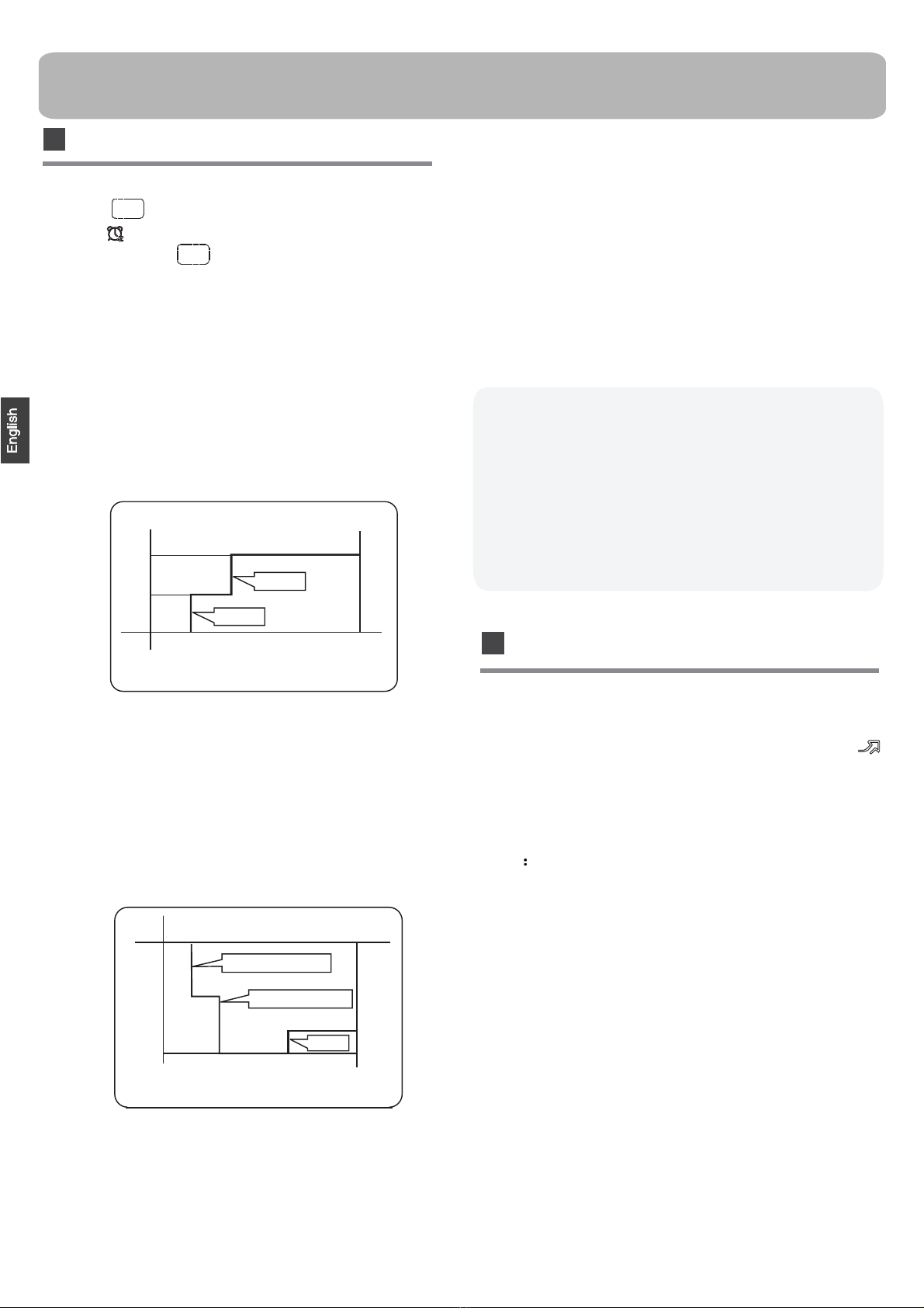
2.In HEAT mode
1 hours after SLEEP mode starts, temp will become
2 C lower than temp.setting. After another 1 hours,
temp decrease by 2 C further. After more another
3 hours, temp.risesby 1 C further.The unit will run
for further 3 hours then stops.Temp. is lower than
temp. setting so that room temperature won't be too
high foryour sleep.
O
O
SLEEP
operation starts SLEEP
operation stops
1 hr
1 hr
3 hrs
3 hrs
Rises 1
O
C
Temp.setting Unit stop
In HEAT mode
Decreases 2
O
C
Decreases 2
O
C
The unit operates in corr
●
esponding sleep mode
set,the quiet sleeping function can't be set up.After the
sleeping function will be cancelled; the machine will be in the
Operation Mode
1. In COOL,DRY mode
SLEEP operation starts SLEEP operation stops
Approx.6hrs
1 hr Rises 1OC
Rises 1OC
Temp.setting Unit stop
In COOL, DRY mode
1 hr
1 hours after SLEEP mode starts,temp.will become
higher than temp.setting.After another 1 hours,
temp.risesby 1 futher .The unit will run for further
6 hours then stops Temp. is higher than temp.setting
so that room temperature won’t be too low for your
sleep.
OC
1
OC
Press button , the remote controller will
show , and then achieve to the sleep function.
Press again this button , the sleep function will
be cancelled.
O
Note
When TIMER function is set, the sleeping function can’t be
set up .After the sleeping function is set up,if user resets
TIMER function, the sleeping function will be cancelled; the
machine will be in the state of timing-on.
Power Failure Resume Function
If the unit is started for the first time, the compressor will not
start running unless 3 minutes have elapsed. When the power
resumes after power failure, the unit will run automatically,
and 3 minutes later the compressor starts running.
SLEEP
SLEEP
3
Note
During TURBO operation, in rapid COOL mode , the room
will show inhomogeneous temperature distribution.
TURBO Operation
(This function is unavailable on some models.)
TURBO Operation
When you need rapid heating or cooling, you can use this function.
Press TURBO button, the remote controller will show ,
and then achieve to the turbo function. Press again this
TURBO button , the turbo function will be cancelled.

Operation
1.After unit starts, select your desired operation mode.
2.Press TIMER button to change TIMER mode. Every
time the button is pressed, display changes as follows:
Remote controller:
BLANK
TIME ON TIME OFF TIME ON-OFF
Then select your desired TIMER mode (TIME ON or
TIME OFF or TIME ON-OFF). " "or " "will flash.
3.Press / button to set time.
It can be adjusted within 24 hours.
●
Hints:
After replacing batteries or a power failure happens, time
●
setting should be reset.
According to the Time setting sequence of TIMER ON or
TIMER OFF, either Start-Stop or Stop-Start can be achieved.
Timer On/Off On-Off Operation CE
All the products are in conformity with the following
European provision:
- Low Voltage Directive 2014/35/EU
-Electomagnetic CompatibilitY 2014/30/EU
ROHS
The products are fulfilled with the requirements in the
directive 2011/65/EU of the European p arliament and of
council on the Restriction of the use of Certain Hazardous
Substances in Electrical and Electronic Equipment (EU
RoHS Directive)
WEEE
DISPOSAL REQUIREMENTS:
Your air conditioning product is marked with this
symbol.This means that electrical and electronic
products shall not be mixed with unsorted
household waste. Do not try to dismantle the
system yourself : the dismantling of the air
EUROPEAN REGULATIONS
CONFORMITY FOR THE MODELS
1
●1+2= kg
R32
2kg2=
1= B
C
D
F E
kg
A
This product contains fluorinated greenhouse gases covered by
the Kyoto Protocol. Do not vent into the atmosphere.
Refrigerant type:R32
GWP* value:675
●
GWP=global warming potential
Please fill in with indelible ink,
and
on the refrigerant charge label supplied with the product.
The filled out label must be adhered in the proximity of the product
●
charging port (e.g. onto the inside of the stop value cover).
A contains fluorinated greenhouse gases covered by the Kyoto
Protocol
B factory refrigerant charge of the product: see unit name plate
C additional refrigerant amount charged in the field
D total refrigerant charge
E outdoor unit
F refrigerant cylinder and manifold for charging
IMPORTANT INFORMATION REGA-
RDING THE REFRIGERANT USED
In accordance with the directive 2012/19/EU of the European
parliament, herewith we inform the consumer about the dis-
posal requirements of the electrical and electronic products.
conditioning system,treatment of the refrigerant, of oil and of
other part must be done by a qualified installer in
accordance
with relevant local and national legislation. Air conditioners
must be treated at a specialized treatment facility for reuse,
recycling and recovery. By ensuring this product is disposed
of correctly, you will help to prevent potential negative cons-
equences for the environment and humen health. Please
contact the installer or local authority for more information.
Battery must be removed from the remote controller and dis-
posed of separately in accordance with relevant local and
nationl legislation.
Contains fluorinated greenhouse gases
covered by the Kyoto Protocol
Healthy airflow Operation
1.Press to starting
Setting the comfort work conditions.
2.The setting of healthy airflow function
Note:
1.After setting the healthy airflow function, the position
grill is fixed.
4.In cooling and dry, using the air conditioner for a long
time under the high air humidity, condensate water may
occur at the grille .
3.The cancel of the healthy airflow function
Notice: Do not direct the flap by hand. Otherwise, the
grille will run incorrectly. If the grille is not run correctly, stop
for a minute and then start, adjusting by remote
controller.
2.In heating, it is better to select the
3.In cooling, it is better to select the
mode.
mode.
TIME OFF-ON
0.5h 0.5h 0.5h 0.5h
Press the button for each time, setting time in the first
12 hours increased by 0.5 hour every time, after 12
hours,increased by 1 hour every time.
Press the button for each time, settiing time in the first
12 hours decreased by 0.5 hour every time, after 12
hours,decreased by 1 hour every time.
After adjust the time,press button and confirm the
time ON or OFF button will not flash any more.
4.Confirm timer setting
5.Cancel timer setting
Press the timer button by times until the time display
eliminated.
Press button to enter additional options,Press this
button continuously, the louvers location will cycle between
in the following three locations, to choose the swing location
what you needed,and then press button to confirm.
Press button to enter additional options,Press this
button continuously, the louvers location will cycle between
in the following three locations again,and then press
button to cancel.
Healthy
airflow
upwarder
Healthy
airflow
downwarder
Present
position
Voltage:230V
Climate:T1
4
Indoor Unit Installation
Driver Torque wrench
(17mm,22mm,26mm)
Nipper
Reamer
Hacksaw Pipe cutter
Gas leakage detector or
soap-and-water solution
Hole core drill Flaring tool
Spanner(17,19 and 26mm) Knife
Measuring tape
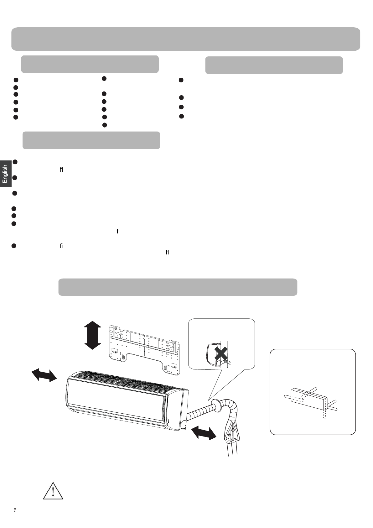
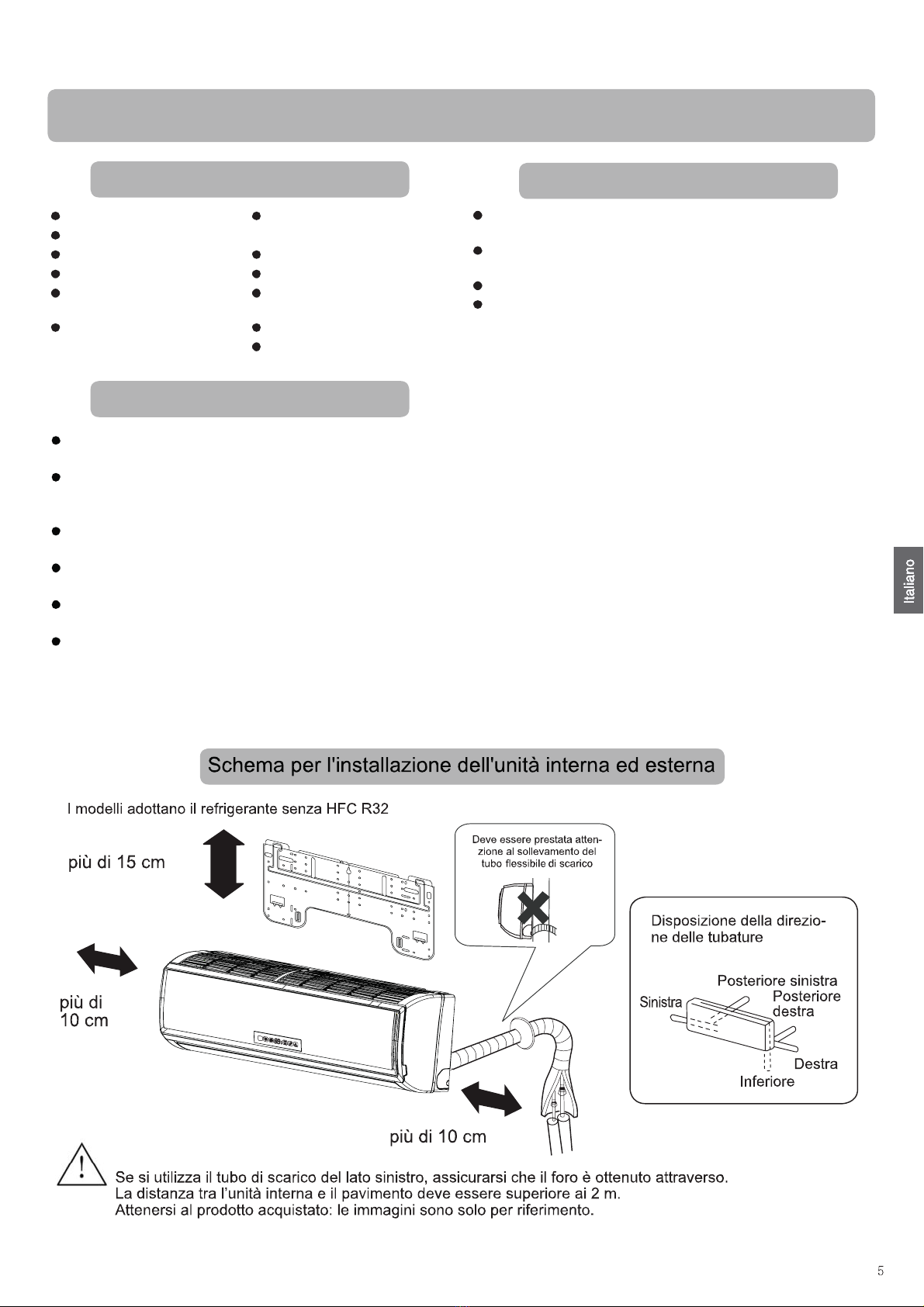
The distance bet
●
ween the indoor unit and the floor should be more than 2m.
The models adopt HFC free refrigerant R32
more than
10cm
more than 15cm
more than 10cm
Attention must be paid to
the rising up of drain hose
Drawing for the installation of indoor units
Please be subject to the actual product purchased,the above picture is just for your reference.
If using the left side drain pipe, make sure the hole is got through.
Necessary Tools for Installation
Selection of Installation Place
Place, robust not causing vibration, where the body can be
supported suf ciently.
Place, not affected by heat or steam generated in the vicinity,
where inlet and outlet of the unit are not disturbed.
Place, possible to drain easily, where piping can be conne-
cted with the outdoor unit.
Place, where cold air can be spread in a room entirely.
Place, nearby a power receptacle, with enough space around.
Place where the distance of more than lm from televisions,
radios, wireless apparatuses and uorescent lamps can be
left.
In the case of xing the remote controller on a wall, place
where the indoor unit can receive signals when the uore-
scent lamps in the room are lightened.
Power Source
Before inserting power into receptacle, check the voltage without
fail.
The power supply is the same as the corresponding nameplate.
Install an exclusive branch circuit of the power.
A receptacle shall be set up in a distance where the power cable
can be reached. Do not extend the cable by cutting it.
Arrangement of piping
directions
Rear left
Rear
right
Right
Below
Left

Indoor Unit Installation
Fix to sid
●
e bar and lintel a mounting bar, Which is separately sold, and
then fasten the plate to the fixed mounting bar.
Refer to the previous article, “ When the mounting plate is fi
position of wall hole.
Make a hole of 60 mm in diame
●
ter, slightly descending to outside the wall
Install piping hole cover and seal it off with putty after installation
1. Carry out, based on the neighboring pillars or lintels, a
to be fixed against the wall, then temporarily fasten the plate
with one steel nail.
2. Make sure once more the proper level of the plate, by hanging a thread
with a weight from the central top of the plate, then fasten securely the
plate with the attachment steel nail.
3. Find the wall hole location A/C using a measuring tape
HSU-09TK1/R32(DB)-IN
HSU-09TK1/R32(DB)-INM
HSU-09TK/R32(DB)-IN
HSU-12TK/R32(DB)-IN
HSU-09TK/R32(DB)-INM
HSU-12TK/R32(DB)-INM
HSU-12TK1/R32(DB)-IN
HSU-12TK1/R32(DB)-INM
HSU-18TK/R32(DB)-IN
HSU-18TK1/R32(DB)-IN
HSU-24TK1/R32(DB)-IN
A=150mm C=120mm
C=113mm
B=
Ø
60mm
A=70mm
B=
Ø
60mm B=
Ø
60mm
B=
Ø
60mm
30mm
45mm
45mm
30mm
35mm
35mm
B=
Ø
60mm
A=120mm C=80mm
B=
Ø
60mm
When the mounting plate is fixed side bar and lintel
Fitting of the Mounting Plate and Positioning of the wall Hole
Lid for right
piping
Lid for under piping pipe
Fix with adhesive tape
Lid for left piping
Indoor/outdoor electric cable and drain hose must be bound with
efrigerant piping by protecting tape.
[ Other direction piping ]
Cut away, with a nipper, the lid for piping according to the piping
direction and then bend the pipe according to theposition of wall
hole. When bending, be careful not to crash pipes.
Connect beforehand the indoor/outdoor electric cable, and then
pull out the connected to the heat insulation of connecting part
specially.
proper leveling
for the plate
rst fixed “,
for the
Making a Hole on the Wall and Fitting the Piping Hole Cover
Drawing of pipe
Installation of the Indoor
●
Unit
[ Rear piping ]
Draw pipes and the drain hose, then fasten them with the adhesive tape
[ Left Left-rear piping ]
In case of left side piping, cut away, with a nipper, the lid for left
piping.
In case of left-rear piping, bend the pipes according to the piping
direction to the mark of hole for left-rear piping which is marked on
heat insulation materials.
1. Insert the drain hose into the dent of heat insulation materials of
indoor unit.
2. Insert the indoor/outdoor electric cable from backside of indoor
unit,and pull it out on the front side, then connect them.
3. Coat the flaring seal face with refrigerant oil and connect pipes.
Cover the connection part with heat insulation materials closely,
and make sure fixing with adhesive tape
Hang surely the unit body onto the upper
notches of the mounting plate. Move the body
from side to side to verify its secure fixing.
In order to fix the body onto the mounting
plate,hold up the body aslant from the
underside and then put it down perpendicularly.
Remove terminal cover at right bottom corner of
indo
●
or unit, then take off wiring cover by removing
its screws.
mounting plate
When you unload the indoor unit,please use your hand to arise
slightly and lift the unit aslant until it leaves the mounting plate.
agraffe mounting plate
the body to leave agraffe,then lift the bottom of the body outward
Heat insulation
material
Drain hose
Piping
Pipe supporting
plate
Indoor/outdoor electric cable
Indoor side Outdoor side
Ø60mm
Wall hole
Thickness of wall
(Section of wall hole) Piping hole pipe
G
When the mounting plate is first fixed
Fixing the indoor unit body
Unloading of indoor unit body
Connecting the indoor/outdoor Electric Cable
Removing the wiring cover
A=130mm C=110mm
35mm
35mm
B=
Ø
60mm B=
Ø
60mm
6

1. Insert from outside the room cable into left side of the wall
hole, in which the pipe has alread
●
y existed.
2. Pull out the cable on the front side, and connect the cable
making a loop.
When connecting the cable, con r
●
m the terminal number of indoor and
outdoor units carefully. If wiring is not correct, proper operation can not
be carried out and will cause defect.
Insert the cable from the back side of the unit, the n pull it out on the fro nt side.
Loosen the screws and insert the cable ends fully into terminal block, then
tighten the screws.
Pull the cab le slightly to make sure the cables have been p rop erly inserted and
tig htened.
After the cab le co nnection, neve r fail to fasten the connected cable with the
wiring cover.
When connecting the cable after installing the indoor unit
When connecting the cable before installing the indoor unit
Note:
1. If the supply cord is damaged, it m
●
ust be replaced by the manufacturer or its
service agent or a similar quali ed person. The type of connecting wire is
H07RN-F.
2. If the fuse on PC board is broken
●
please change it with the type of
3. The wiring method should be in l
●
ine with the local wiring standard.
4. After installation, the power plug should be easily reached.
5. A breaker should be incorporated into xed wiring. The breaker should be
all-pole switch and the distance between its two contacts should be not less
than 3mm.
T.3.15A/250VAC (Indoor).
To Outdoor unit
Connecting wiring
4G1.0mm
2
Code
indic ation Trouble description Analyze and diagnose
E 1
E 2
E 4
E 7
E14
Heat-exchange
sensor failure
Ind oor EE P R OM
error
C om m u nic ation
fault between
indoor and outdoor
units
Indo or fan m otor
m alfunction
Operation halt due to breaking
of wire inside the fan m otor;
O peration halt due to breaking
of the fan m otor lead w ires;
Detection error due to faulty
indoor unit PCB;
Indoor unit- outdoor unit signal
transm iss ion error du e to w iring
error;
Faulty PC B;
Faulty E EP R O M d ata;
Faulty E EP R O M ;
Faulty P CB ;
Faulty connector connection;
F aulty th erm istor;
Faulty P C B;
Room temperature
sensor failure
The power source must be exclusively used for air conditioner.
In the case of installing an air conditioner in a moist place, please install
an ea
For installation in other places, use a circuit breaker as far as possible.
Pipe cutting is carried out with a pipe cutter and burs must be removed.
After inserting the are nut, aring work is carried out.
Power Source Installation
Cutting and Flaring Work of Piping
Flare tool for R410A Conventional are tool
Clutch-type clutch-type(Rigid-type) Wing-nut type (Imperial-type)
A 0~0.5mm 1.0~1.5mm 1.5~2.0mm
rth leakage breaker.
Lean Damage of are Partial Too outside
tcerrocnItcerroC
On Drainage
It becomes
high midway.
The gap with the
ground is too small.
There is the bad
smell from a ditch
It waves.
The end is imm-
ersed in water.
Please install the drain hose so as to be downward slope without fail.
Please don’t do the drainage as shown below.
Please pour water in the drain pan of the indoor unit, and
is carried out surely to outdoor.
In case that the attached drain hose is in a room, please apply heat
insulation to
Less than
5cm
con rm that
drainage
it without fail.
Crack
Indoor unit
Check Items for Test Run
Gas leak from pipe connecting?
Heat insulation of pipe connecting?
Are the connecting wirings of indoor and outdoor rmly
Is the connecting wiring of indoor and outdoor rmly xed?
Is drainage securely carried out?
Is the earth line securely connected?
Is the indoor unit securely xed?
Is power source voltage abided by the code?
Is there any noise?
Is the lamp normally lighting?
Are cooling and heating (when in heat pump) performed normally?
Is the operation of room temperature regulator normal?
Please kindly explain to our customers how to
operate through the instruction manual.
inserted to the terminal block?
Put check mark in boxes
Flare tooling die 1.Cut pipe 2.Remove burs
3.Insert the are nut 4.Flare pipe
On Drainage
Check for Installation and Test Run
7
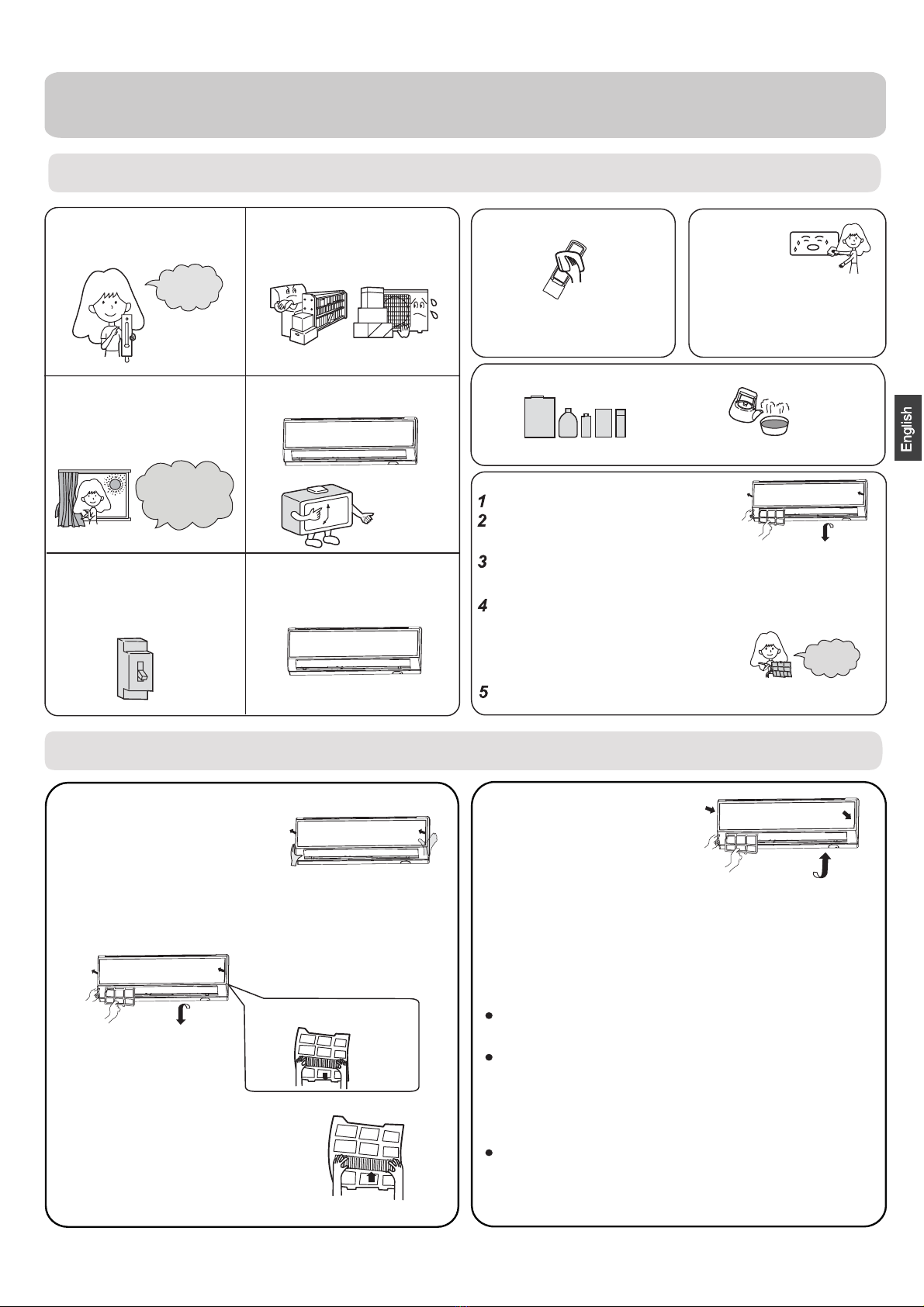
Maintenance
Setting of proper room
temperature
Close doors and windows
●
during operation
If the unit is not to be used
●
for a long time, turn off the
●
power supply main switch.
Use the timer effectively
Use the louvers effectively
Do not block the air inlet
or outlet
Proper
temperature
During cooling operation
prevent the penetration
of direct sunlight with
curtain or blind
OFF
Remote Controller Indoor Body
1.Open the lnlet Grille
2.Detach the standard air filter
●
3.Attach Air Purifying Filter
●
4.Attach the standard air filter
(Necessary installation)
5.Close the Inlet Grille
Close the Grille surely
Slide the knob slightly upward to
release the filter, then withdraw it.
Put air purifying filter appliances into the
right and left filter frames.
NOTE:
The photocatalyst air purifying filter will be solarized in fixed
time. In normal family, it will be solarized every 6 months.
Prop up the inlet grille by using a
small device named grille-support
ATTENTION:
Please keep the bacteria-killing medium air purifying filter in
avoid long time directly sunshine
when you stop using it,or its ability of sterilization will be
reduced.
The bacteria-killing medium air purifying filter will be used
for a long time,no need for replacement. But in the period
of using them ,you should remove the dust frequently by
which located in the right side of
the indoor unit.
using vacuum cleaner or flaping them lightly,otherwise ,
its performance will be affected.
the cool and dry conditions
For Smart Use of The Air Conditioner
Replacement of Air Purifying Filter
The white side of the photocatalyst air purifying filter
face outside,and the black side face the unit The green
side of the bacteria-killing medium air purifying filter face
outside,and the white side face the unit.
Do not usewater,wipe the controller
with a dry cloth.Do not use glass
cleaner or chemical cloth.
wipe the air conditioner by using a
soft and dry cloth.For serious stains,
use a neutral detergent diluted with
water.Wring the water out of the
cloth before wiping,then wipe off the
detergent completely.
Air Filter cleaning
Open the inlet grille by pulling it upward.
Remove the filter.
Clean the filter.
Attach the filter.
Close the inlet grille.
Push up the filter's center tab slightly until it is
from the stopper, and remove the filter downward.
Use a vacuum cleaner to remove dust, or wash the filter with
water.After washing, dry the filter completely in the shade.
Attach the filter correctly so that the "FRONT" indication
facing to the front.Make sure that the filter is
fixed behind the stopper.If the right
attached correctly, that
Do not use the following for cleaning
Gasoline,benzine, thinner or cleanser
ay damage the coating of the unit. Hot water over 40OC(104OF) may
discoloring or deformation.
Once every
two weeks
mcause
released
is
completely
and left filters are not
may cause defects.
Detach old Air Purifying Filter
8

the power supply cord
●
and so on.
2.Do not install in the place where there is any
possibility of inflammable gas leakage around the unit.
3.Do not get the unit exposed
to vapor or oil steam.
Cautions
Please call Sales/Service Shop for the Installation.
Do not attempt to install the air conditioner by yourself because improper works
may cause electric shock, fire, water leakage.
Connect the earth
cable.
ea
●
rthing
WARNING
When abnormality such as burnt-small found,
immediately stop the operation button and
contact sales shop.
OFF
Use an exclusive
power source
with a circuit
breaker
ENFORCEMENT
Connect power supply cord
to the outlet completely Use the proper voltage
Do not use power supply
cord in a bundle.
Take care not to damage
the power supply cord.
1.Do not use power supply cord extended
or connected in halfway
STRICT
ENFORCEMENT
STRICT
STRICT
ENFORCEMENT PROHIBITION
PROHIBITION
PROHIBITION
PROHIBITION
Do not start or stop the
operation by disconnecting
Do not channel the air flow directly
at people, especially at infants or
the aged.
Do not try to repair or
reconstruct by yourself.
Do not use for the purpose of storage of
●food, art work, precise equipment,
breeding, or cultivation.
CAUTION
Take fresh air occasionally especially
when gas appliance is running at the
same time.
PROHIBITION
STRICT
ENFORCEMENT
Do not operate the switch with
wet hand.
PROHIBITION
●
PROHIBITION
PROHIBITION PROHIBITION
PROHIBITION
Do not install the unit near a fireplace
or other heating apparatus. Check good condition of the
installation stand
Do not pour water onto the unit
for cleaning
PROHIBITION
Do not place animals or plants in
the direct path of the air flow
Do not place any objects on or
climb on the unit.
Do not place flower vase or water
containers on the top of the unit.
Do not insert objects into the air
inlet or outlet.
PROHIBITION
PROHIBITION
PROHIBITION
STRICT
ENFORCEMENT
Check proper
installation of the
drainage securely
WARNING
9
Trouble shooting
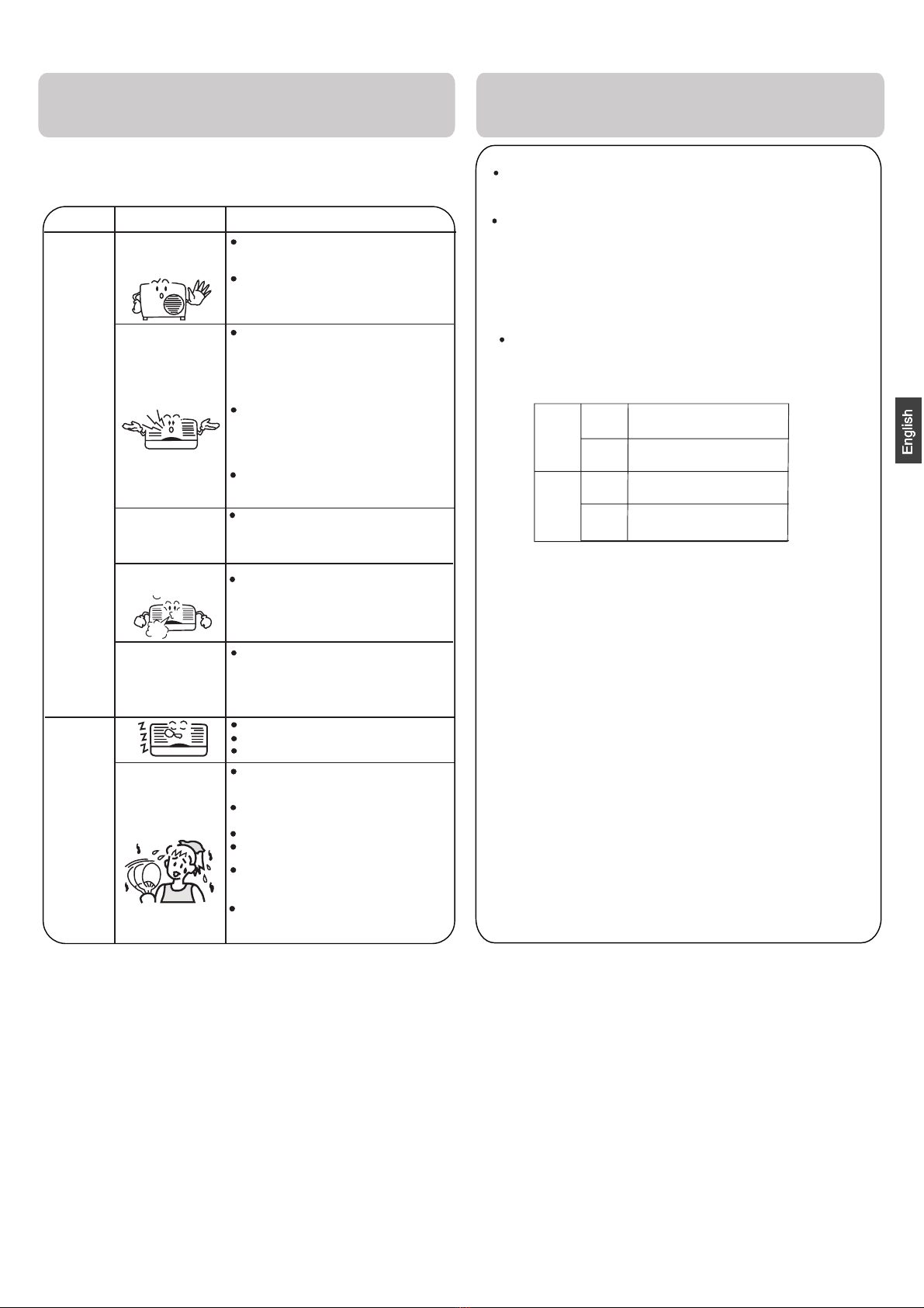
Normal
Performance
inspection
Noise is heard
Phenomenon Cause or check points
The system
immediately.
Smells are
generated.
Mist or steam are
●
Multiple
check
Poor cooling
When unit is stopped, it won't restart
elapsed to protect the system.
When the electric plug is pulled out
and reinserted, the protection circuit
During unit operation or at stop,
a swishing or gurgling noise may
(This noise is generated by
refrigerant flowing in the system.)
During unit operation, a cracking
noise may be heard.This noise is
temperature changes.
Should there be a big noise from
filter may be too dirty.
This is because the system
circulates smells from the interior
During COOL or DRY operation,
This is due to the sudden cooling
Is power plug inserted?
Is there a power failure?
Is fuse blownout?
Is the air filter dirty?
Are there any obstacles before
Is temperature set correctly?
●
Are there some doors or
Is there any direct sunlight
●
through the window during the
Are there too much heat sources
or too many people in the room
In dry mode,
fan
speed can’t be
changed.
In DRY mode, when room temperature
setting+2 oC,unit will run
regardless of FAN setting.
during cooling operation?
cooling operation?(Use curtain)
windows left open?
inlet and outlet?
Normally it should be cleaned
every 15 days.
intermittently at LOW speed
becomes lower than temp.
indoor unit may blow out mist.
of indoor air.
air such as the smell of furniture,
paint, cigarettes.
air flow in unit operation, air
generated by the casing expanding
or shrinking because of
be heard.At first 2-3 minutes after
unit start, this noise is more noticeable.
will work for 3 minutes to protect the
air conditioner.
immediately until 3 minutes have
Cautions
3. If the fuse of indoor unit on PC board is
it with the type of T. 3.15A/ 250V outdoor
broken,change it with the type of T.25A/250V
The refrigerating circuit is leak-proof.
1.Applicable ambient temperature range:
Specifications
The machine is adaptive in following situation
The power plug and connecting cable acquired the local
2. If the power supply cord is damaged, it must be replaced
manufacturer qualified
person.
4. The wiring method should be in line with the local wiring
5. After installation, the power plug should be easily reached.
6. The waste battery should be disposed properly.
7. The appliance is not intended for use
persons
without supervision.
8.Young children should be supervised
with
the appliance.
9. Please employ the proper power plug,
cord.
11.In order to protect the units,please turn
30 seconds later, cutting off the power.
10.
Cooling
Indoor
Maximum:D.B/W.B
Maximum:D.B/W.B
D.B
Maximum:D.B
D.B
Minimum:D.B/W.B
Maximum:D.B/W.B
Minimum:D.B/W.B
Outdoor
Indoor
Outdoor
Heating
35oC/24oC
24oC/18oC
oC
43oC/26oC
-10oC
27oC
21oC/15oC
oC
-15
Minimum:
Minimum:
or its service agent or a similar
broken,please
. If the fuse of
standard.
by young children or
to ensure that they
which fit into the
must have
off the A/C first,
Before asking for service, check the following
first.
blown out.
does not restart
by the
change
unit is
infirm
do not play
power supply
attestation.
and at least
10
Do not obstruct or cover the ventilation
conditoner.Do not put fingers
inlet/outlet and swing louver.
This appliance is not intended for use by persons (including children)
with reduced physiced, sensory or mental capabilities or lack of
experience and knowledge, unless they have been given supervision
or instruction concerning use of appliance by person responsible for
their safety. Children should be supervised to ensure that they do not
play with the appliance.
grille of the air
or any other things into the
10

9
●
1
2
8
5
10
Indice
PARTI E FUNZIONI
FUNZIONAMENTO
INSTALLAZIONE UNITÀ INTERNA
MANUTENZIONE
AVVERTENZE
RISOLUZIONE DEI PROBLEMI
Leggere attentamente le
precauzioni in questo manuale
prima di utilizzare l’unità.
Questo apparecchio contiene
R32.
Tenere questo manuale dove l’utente può trovarlo facilmente.
ATTENZIONE:
Non utilizzare mezzi per accelerare il processo di sbrinamento o per pulire che siano diversi da quelli
raccomandati dal produttore.
L'apparecchio deve essere conservato in una stanza senza fonti di ignizione a funzionamento continuo (ad
esempio: fiamme libere, un apparecchio a gas in funzione o un riscaldatore elettrico in funzione).
Non perforare né bruciare.
Siate consapevoli del fatto che i refrigeranti potrebbero non avere un odore.
L'apparecchio deve essere installato, messo in funzione e conservato in una stanza con una superficie del
suolo più grande di 3m.
Se il cavo di alimentazione è danneggiato, deve essere sostituito dal produttore, il suo agente dei servizi o da
persone similmente qualificate per evitare rischi.
Questo apparecchio può essere usato dai bambini di età pari o superiore agli 8 anni e da persone con ridotte
capacità fisiche, sensoriali o mentali o mancanza di esperienza e conoscenza nel caso in cui abbiano ricevuto
supervisione o istruzioni riguardanti l'uso dell'apparecchio in modo sicuro e capiscano i rischi coinvolti. I
bambini non devono giocare con l'apparecchio. Le operazioni di pulizia e manutenzione non devono essere
effettuate dai bambini senza supervisione.
Il metodo di cablaggio deve essere conforme allo standard locale di cablaggio.
Il tipo di cavo di connessione è H07RN-F.
Tutti i cavi devono possedere il certificato di autenticazione europeo. Durante l'installazione, quando si
interrompono i cavi di collegamento, è necessario assicurarsi che il filo di messa a terra sia l'ultimo ad essere
interrotto.
L'interruttore del condizionatore dovrebbe essere un interruttore onnipolare; e la distanza tra i due contatti
non dovrebbe essere inferiore a 3mm. Tali mezzi di scollegamento devono essere incorporati nel cablaggio.
Assicurarsi che l’installazione venga eseguita secondo la regolazione locale di cablaggio da parte di
professionisti.
Assicurarsi che la connessione al suolo sia corretta e affidabile.
Gli interruttori devono essere installati.
Non utilizzare un refrigerante diverso da quello specificato sull’unità esterna (R32) durante l’installazione,
lo spostamento e la riparazione. L’utilizzo di altri refrigeranti potrebbe causare problemi o danneggiare
l’unità, e lesionare la persona.
2
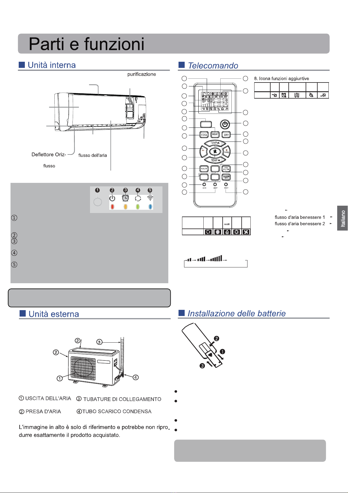
La griglia di aspirazione pu
●
ò variare da quella indicata nel
manuale a seconda del prodott
●
o acquistato
1
Rimuovere il coperchio delle bat-
terie;
Installare le batterie come mo-
strato. 2 batterie R-03, tasto di
ripristino;
Accertarsi di rispettare le polarità
" + "/"-";
●liotsopaerettemiridniuq,airettabaleraciraC
coperchio.
Nota:
●La distanza tra la testina di trasmissione del segnale e il foro del ricevito-
re deve essere di massimo 7 metri, senza ostacoli.
Se nella stanza è installata una lampada al neon con starter elettronico o
un telefono wireless, il ricevitore potrebbe essere disturbato nella ricezio-
ne del segnale, pertanto la distanza con il condizionatore deve essere
diminuita.
Una visualizzazione di tutte le icone o poco chiara, sta ad indicare che le
batterie sono quasi esaurite. Sostituirle.
Se il telecomando non funziona normalmente, rimuovere le batterie e
rimetterle a posto qualche minuto più tardi.
1
2
3
4
Suggerimento:
Rimuovere le batterie se l'unità non viene utilizzata per periodi prolunga-
ti. Se dovessero apparire delle icone una volta spento, basta premere il
tasto di reset.
1
2
3
4
5
9
10
11
12
13
14
15
16
17
8
22
23
24
25
19
20
21
18
7
6
Modalità
operativa
QUITE
(silen-
zioso)
SO-
SPEN-
SIONE
Riscaldamento
elettrico
integrato
BENES-
SERE
ALIMEN-
TAZIONE
Telecomando
9. Pulsante TURBO
10. Pulsante HEAT
11. Pulsante COOL
12. Pulsante OSCILLAZIONE
13. Pulsante VENTILATORE
14. Pulsante HEALTH
15. Pulsante SLEEP
16. Pulsante BLOCCO
Usato per bloccare i pulsanti e la
visualizzazione del LED.
17. Pulsante LUCE
Controlla l'illuminazione lo spegnimen-
to del pannello di visualizzazione LED
interno.
18. Pulsante ACCENSIONE/SPEGNI-
MENTO
19. Pulsante DEUMIDIFICATORE:
20. Pulsante TEMPERATURA
21. Pulsante OSCILLAZIONE
22. Pulsante TIMER
23. Pulsante FUNZIONE EXTRA
Funzione:
Aria inviata
Posizione
Posizione
---
---
---
---
---
A-B yard
Sospensione
Alimentazione
24. Pulsante ANNULLA / CONFERMA
Funzione: Imposta e annulla il timer e
altre funzioni addizionali.
25. Pulsante REIMPOSTA
Se il telecomando avesse un aspetto
anomalo, usare un oggetto appuntito
per premere questo pulsante e reset-
tare il telecomando
1. Icona modalità
Modalità
operativa
AUTO
(auto-
matico)
COOL
(condi-
ziona-
tore)
DRY
(deu-
-
catore)
HEAT
(riscal-
damen-
to)
VENTI-
LATO-
RE
Telecomando
2. Icona invio del segnale
3. Icona OSCILLA
4. Icona VELOCITÀ VENTILATO-
RE
5. Icona BLOCCO
6. Icona TIMER DISATTIVA TI-
MER
icona ATTIVA TIMER
7. Icona TEMP
La funzione benessere non è disponibile per alcune unità.
basso medio alto automatico
Visualizza
circolazione
Filtro di
dell’aria
(interno)
Interruttore
d'emergenza
Aletta verti-
cale
(regolare il
da destra a
sinistra)
Scheda del display
zontale
(dirige il dell'aria
verso l'alto o verso il bas-
so. Non regolare a mano)
Uscita
Gliglia presa d'aria
Pannello
TURBO
SWING
SLEEP
TIME
ON TIME
OFF
Indicatore modalità di funzionamento(accerso quando il
compressore è in marcia)
WIFI(opzionale)
Display
Ricevitore segnale emesso dal telecomando
(quando il segnale emesso dal telecomando è ricevuto emette un
segnale acustico)
Indicatore alimentazione(acceso quando l’unità è in marcia)
Indicatore modalità di timer (acceso quando la modalità di
funzionamento timer è selezionata)
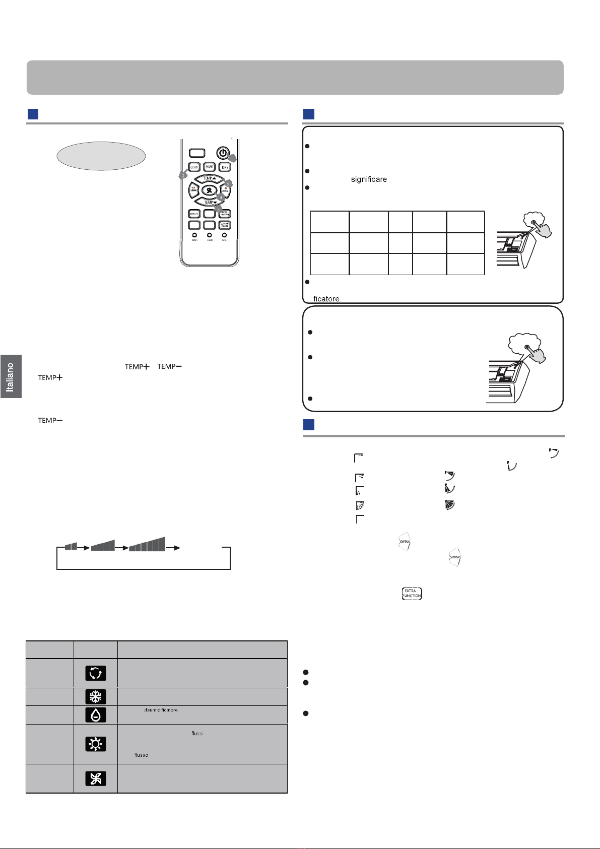
Funzionamento
Funzionamento di base
1. Avviare l’unità
Tenere premuto ON/OFF sul telecomando finché l'unità si
avvia.
2. Selezione della modalità operativa
3. Selezionare l'impostazione della temperatura
●
Premere il pulsante / .
Ogni volta che viene premuto il pulsante, le impo-
●
stazioni temperatura aumentano di 1°C. Se il pul-
sante viene tenuto premuto, la temperatura aumen-
●
terà rapidamente.
Ogni volta che viene premuto il pulsante, le im-
postazioni temperatura diminuiscono di 1°C. Se
il pulsante viene tenuto premuto, la temperatura
diminuirà rapidamente
Selezionare una temperatura desiderata.
4. Selezione della velocità del ventilatore
ne la velocità del ventilatore
cambia come segue:
Telecomando:
Il condizionatore funziona alla velocità del ventilatore visua-
lizzata.
Se ventilatore è impostato in modalità automatica, l’unità
regolerà automaticamente la velocità del ventilatore in base
alla temperatura ambiente.
●
Funzionamento emergenza e collaudo
logeR azione della direzione del flusso d’aria
4.
a destra e a sinistraaira’lledossulfled)elaunam(enoizalogeR
Spostare la lama verticale usando la manopola sul condizio-
natore per regolare la direzione verso destra o verso sini-
stra, facendo riferimento alla fig.
Attenzione:
Quando si regola l'aletta a mano, spegnere l'unità.
In caso di alto tasso di umidità si potrebbe avere della
condensa all'uscita dell'aria se tutte le leve verticali sono
regolate a destra o a sinistra.
Si consiglia di non mantenere l'aletta orizzontale rivolta
verso il basso a lungo in modalità condizionatore o deumi-
dificatore per evitare la condensa.
●
Nota:
Quando si effettua il riavvio dopo aver effettuato lo spegni-
mento remoto, il telecomando memorizzerà automaticamen-
te la posizione di oscillazione precedente impostare la posi-
zione oscillante
Telecomando
assaB medio alto automatico
Visualizza
circolazione
Funzionamento d’emergenza:
Usare questa modalità solo quando il telecomando è difettoso o è
andato perso. In caso di emergenza, il condizionatore può funzionare in
automatico per un po'.
Quando è premuto l’interruttore d’emergenza, sarà emesso un BEEP
una volta a l’inizio della procedura.
Quando l’interruttore viene attivato per la prima volta e viene avviata
l'operatività di emergenza, l'unità si avvierà automaticamente nelle
seguenti modalità:
Temperatura
ambiente
Temperatura
designata
Modali-
tà timer
Velocità
ventola
Modalità
operativa
Sopra i 23°C 26°C N.
Sotto i 23°C 23°C N.
Non è possibile cambiare le impostazioni della temperatura e la velocità
della ventola, inoltre non è possibile usare il timer o la modalità deumidi-
Beep
Collaudo di funzionamento:
L'interruttore del collaudo di funzionamento e quello di emergenza corrispondono.
Usare questo interruttore per il collaudo di funziona-
mento quando la temperatura d’ambiente è inferiore
ai 16°C, non usarlo per il normale funzionamento.
Tenere premuto l’interruttore per il collaudo di fun-
zionamento per più di 5 secondi. Una volta sentito
il beep due volte, rilasciare la pressione dall'inter-
ruttore: il raffreddamento si avvia con la velocità del
flusso d'aria "Hi" (alto).
Con questa modalità di funzionamento, il motore della
ventola dell'unità interna funzionerà ad alta velocità.
Beep beep
Pulsante CONDIZIONATORE: modalità condizionatore
Pulsante RISCALDAMENTO: modalità riscaldamento
Pulsante DEUMIDIFICATORE: Modalità deumidificatore
Premere il pulsante VENTILATORE. A ciascuna pressio-
Modalità di
funzionamento atoNodnamoceleT
AUTOMATICO
In modalità di funzionamento automatico, il condizionatore selezionerà au-
tomaticamente il funzionamento condizionatore o riscaldamento in base alla
temperatura ambiente. Se ventilatore è impostato in modalità automatica, il
condizionatore regolerà automaticamente la velocità della ventola in base
alla temperatura ambiente.
CONDIZIONA-
TORE
DEUMIDIFI-
CATORE
In modalità quando la temperatura d'ambiente supera di 2
°C la temperatura impostata, l'unità si avvierà ad intervalli a velocità bassa
indipendentemente dall'impostazione del ventilatore.
RISCALDA-
MENTO
In modalità riscaldamento, l'aria calda uscirà dopo un breve periodo a causa
della funzione di prevenzione dei d'aria fredda.
Se ventilatore è impostato in modalità automatica, l’unità regolerà automati-
camente la velocità del ventilatore in base alla temperatura ambiente.
Passando da una singola unità interna a due o più unità, l'unità disattiva non
invierà d'aria nei primi 7 minuti e la temperatura visualizzata potrebbe
essere differente dalla temperatura effettiva.
VENTILATO-
RE
In modalità ventilatore, l’unità non funzionerà in modalità condizionatore o
riscaldamento ma solo in modalità ventilatore. La modalità automatica non è
disponibile in modalità ventilatore. Inoltre, l'impostazione della temperatura
viene disabilitata. In modalità VENTIL ATORE, la funzione sospensione non è
disponibile.
AUTOMA-
TICO
CONDIZIO-
NATORE
AUTOMA-
TICO
RISCALDA-
MENTO32
Pos.1
Pos.2
Pos.3
Pos.4
Pos.5
3. Premendo il pulsante .per inserire :Pos.2 / Pos.3.
1. Sportellino verticale Telecomando
COOL/DRY/AUTO(Initialstate):
HEAT(Initial state):
(Autoswing)
(no)
2. Premendo il pulsante , si passa a Pos.4
Premendo nuovamente il pulsante , lo sportellino verticale si
arresta sulla posizione attuale e la funzione di oscillazione viene
annullata
2
TIM E
OF F
TIM E
ON
TURBO
S LE EP
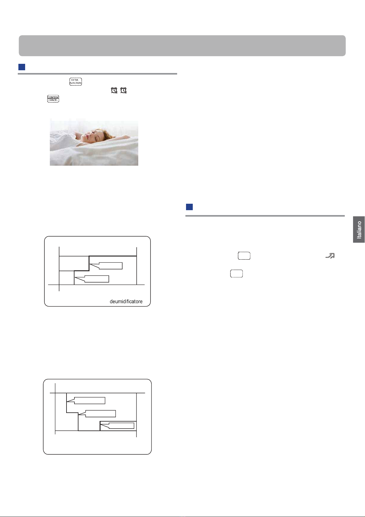
Funzionamento
Funzionamento sospensione
Premere il pul
●
sante per inserire opzioni aggiuntive,
quando viene visualizzato il ciclo su , lampeggerà. Quin-
di premere per entrare nella funzione sospensione.
Modalità di funzionamento
1. In modalità condizionatore, deumidificatore
1 ora dopo che la modalità sospensione si è avviata, la
temperatura si alzerà di 1
°C rispetto alla temperatura im-
●
postata. Dopo un'altra ora la temperatura salirà ancora di
1°C. L'unità rimarrà in funzione per ulteriori 6 ore quindi si
arresterà. La temperatura è maggiore della temperatura
impostata in modo tale che la temperatura ambiente non
sia troppo bassa per il sonno.
2. In modalità riscaldamento
1 ora dopo che la modalità sospensione si è avviata, la
temperatura si abbasserà di 2°C rispetto alla temperatura
●
impostata. Dopo un'altra ora la temperatura scenderà
ancora di 2°C. Dopo altre 3 ore la temperatura salirà di
1°C L'unità rimarrà in funzione per altre 3 ore, quindi si
arresterà. La temperatura è inferiore della temperatura
impostata in modo tale che la temperatura ambiente non
●
sia troppo alta per il sonno.
3. In modalità automatica
L'unità opera nella modalità sospensione corrispondente
in base alla modalità di funzionamento selezionata auto-
maticamente.
4. In modalità ventilatore
Non ha la funzione sospensione
5. Impostare il cambio della velocità del ventilatore
durante la sospensione
Se la velocità di ventilazione è alta o media, prima di
impostare la sospensione, impostare per abbassare la
velocità di ventilazione dopo la sospensione.
Se la ventilazione è debole, non modificarla.
Nota
Se è impostata la funzione TIMER, la funzione di sospensio-
ne non può essere impostata. Una volta impostata la funzio-
ne di sospensione, se l'utente reimposta la funzione TIMER,
la funzione di sospensione verrà annullata e la macchina
entrerà nello stato di temporizzazione attivata.
Funzionamento alimentazione
Nota:
Durante il funzionamento in modalità potenza, in modalità
getta a una distribuzione disomogenea della temperatura.
In modalità condizionatore,
SLEEP entra in funzione SLEEP si arresta
Circa 6 ore
1 ora
1 ora Si alza di 1°C
Si alza di 1°C
Impostazione temperatura Arresto dell’unità
In modalità riscaldamento
Impostazione temperatura
●
Arresto dell’unità
1 ora
1 ora
Diminuisce di 2°C
Si alza di 1°C
SLEEP
entra in funzione SLEEP si arresta
3 ore
Diminuisce di 2°C
riscaldamento o condizionatore rapido, la stanza sarà sog
Un funzionamento silenzioso per un lungo periodo ha l'effetto
di non raffreddare o riscaldare eccessivamente.
3
Funzionamento ALIMENTAZIONE
Quando è necessario un riscaldamento o raffreddamento
rapido, è possibile usare questa funzione.
Premere il pulsante , il telecomando mostrerà
quindi raggiungere la funzione ALIMENTAZIONE. Premere di
nuovo il pulsante , la funzione ALIMENTAZIONE verrà
annullata.
TURBO
,
TURBO
Funzionamento
Funzionamento timer On/Off On-Off
1. Una volta avviata l'unità, selezionare la modalità di funzio-
namento desiderata.
2. Premere il pulsante TIMER per cambiare la modalità
timer. Ogni volta che si preme il pulsante, il display cambia
come segue:
Telecomando:
BLANK
●
3. Per impostare l'ora, premere il pulsante
●
/
Premendo il pulsante per ogni ora, l'ora impostata nelle
prime 12 ore aumenta di mezz'ora, nelle 12 ore succes-
sive aumenta di 1 ora.
Premendo il pulsante per ogni ora, l'ora impostata nelle
prime 12 ore diminuisce di mezz'ora, nelle 12 ore suc-
cessive diminuisce di 1 ora.
Può essere regolato sulle 24 ore.
4. Conferma impostazioni timer
●
Dopo aver regolato l'ora, premere il pulsante e confer-
mare l'ora. Il pulsante ON/OFF non lampeggerà più.
5. Annullare impostazioni timer
Premere il pulsante timer per più volte finché l'ora visualiz-
zata non viene eliminata.
Suggerimenti:
dopo avere sostituito le batterie, oppure dopo un black-out, l’
impostazione dell'ora deve essere configurata di nuovo.
Funzionamento con flusso d'aria be
●
-
nessere
1. Premere per iniziare
Impostare le condizioni di lavoro ottimali.
2. Impostazioni della funzione flusso d'aria benessere
Premere il pulsante button per inserire opzioni aggiun-
tive. Premere ripetutamente questo pulsante in modo che
la posizione delle leve cambi a ciclo tra le tre posizioni, per
scegliere la posizione desiderata dell'oscillazione, quindi
premere il pulsante per confermare.
3. Annullamento del flusso d'aria benessere. Premere il
pulsante per inserire le opzioni aggiuntive. Premere
ripetutamente questo pulsante in modo che la posizione
delle leve cambi a ciclo tra le tre posizioni, quindi premere il
pulsante per annullare.
Avviso: Non direzionare l'aletta con la mano Altrimenti la gri-
glia potrebbe non funzionare correttamente. Se la griglia non
funziona correttamente, ferma
●
re per un minuto quindi riavvia-
re l'unità, eseguendo le regolazioni con il telecomando.
Nota:
1. Una volta impostata la funzione flusso d'aria benessere,
la posizione della griglia viene fissata.
2. In riscaldamento, è meglio selezionare la modalità .
3. In raffreddamento, è meglio selezionare la modalità .
4. In condizionatore e deumidificatore, utilizzando il condi-
zionatore per un lungo periodo di tempo in condizioni di alto
tasso di umidità, dalla griglia potrebbero cadere delle gocce
d'acqua.
CONFORMITÀ AI REGOLAMENTI
EUROPEI PER I MODELLI
CE
Tutti i prodotti sono conformi alle seguenti disposizioni euro-
pee:
- Direttiva bassa tensione 2014/35/UE
- Compatibilità elettromagnetica 2014/30/UE
ROHS
I prodotti sono conformi ai requisiti della direttiva 2011/65/EU
del Parlamento e del Consiglio Europeo sulla limitazione
dell'uso di alcune sostanze pericolose nei dispositivi
elettrici ed elettronici (direttiva RoHS UE).
WEEE
In conformità alla direttiva 2012/19/EU del Parlamento Eu-
ropeo, informiamo il consumatore relativamente ai requisiti
per lo smaltimento dei prodotti elettrici ed elettronici.
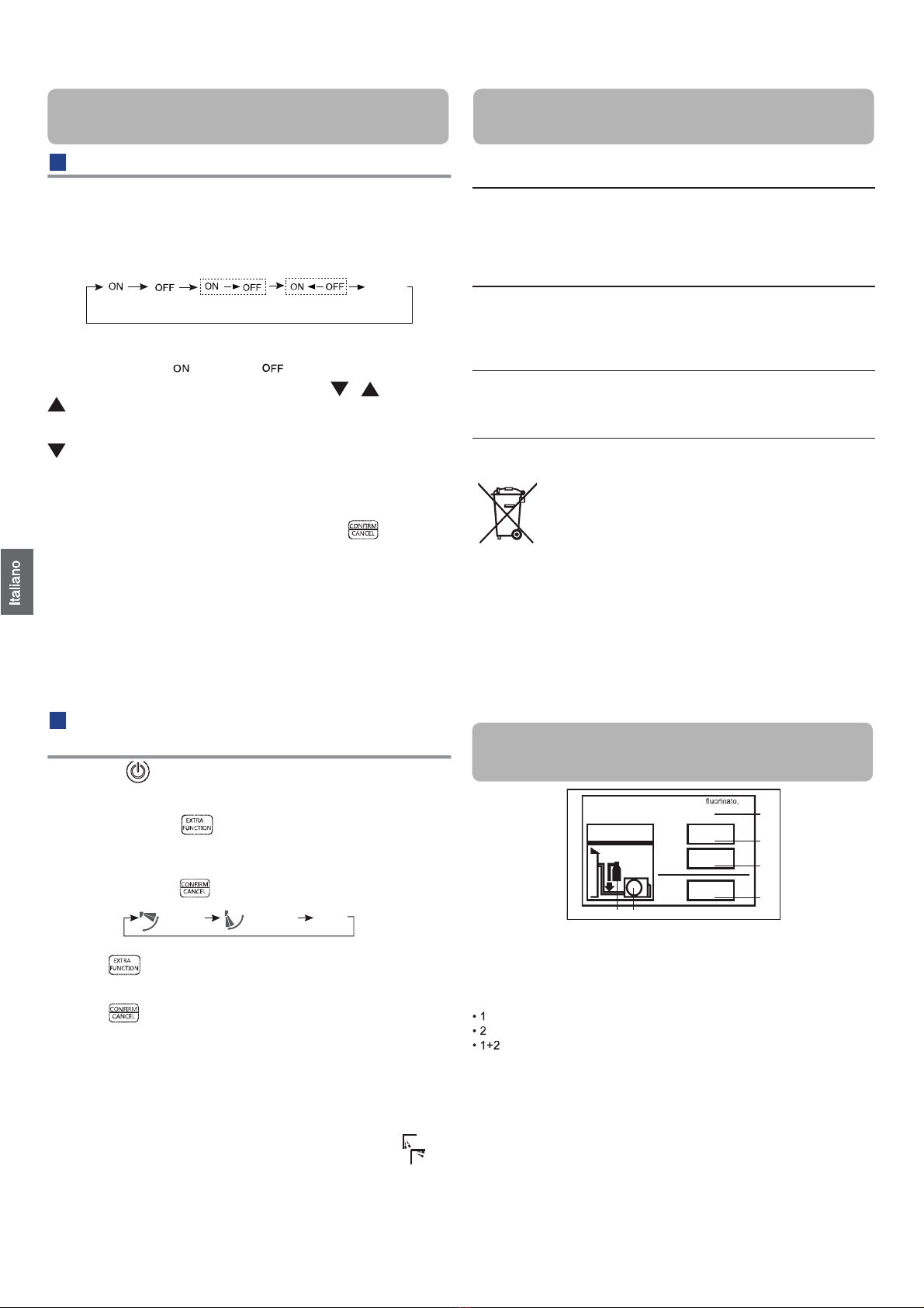
REQUISITI PER LO SMALTIMENTO:
Il condizionatore acquistato è contrassegnato con questo
simbolo, che sta a significare che le parti elettriche ed elet-
troniche non devono essere mischiate con i
rifiuti domestici. Non tentare di aprire il sistema
da soli: lo smontaggio del sistema del condi-
zionatore, il trattamento del refrigerante, del-
l'olio e di altre parti deve essere effettuato da
un installatore qualificato conformemente alle leggi locali e
nazionali pertinenti. I condizionatori devono essere trattati
presso strutture di trattamento specializzate per il riutilizzo,
il riciclaggio e il ricondizionamento. Garantendo che questo
prodotto sia smaltito correttamente, si aiuterà a prevenire
possibili conseguenze negative per l'ambiente e la salute
umana. Contattare l'installatore o l'autorità locale per ulte-
riori informazioni. La batteria deve essere rimossa dal tele-
comando e smaltita separatamente in conformità alle leggi
locali e nazionali pertinenti.
IMPORTANTI INFORMAZIONI RELATIVE
AL REFRIGERANTE UTILIZZATO
1
1+2= kg
R32
2kg
2=
1= B
C
D
F E
kg
A
Questo prodotto contiene gas serra fluorinato, oggetto del Protocollo di
Kyoto. Non lasciar sfogare nell'atmosfera.
Tipo di refrigerante:R32
Valore GWP* :675
GWP=global warming potential
Inserire, con inchiostro indelebile,
il carico di refrigerante del prodotto inserito in fabbrica
il quantitativo aggiuntivo di refrigerante caricato sul campo e
il carico di refrigerante totale
sull'etichetta con il carico di refrigerante in dotazione con il prodotto.
L'etichetta compilata deve essere attaccata accanto alla porta di carica-
mento del prodotto (es. all'interno del coperchio con il valore di arresto).
A contiene gas serra fluorinato, trattato nel Protocollo di Kyoto
Protocollo
B carico di refrigerante del prodotto inserito in fabbrica: vedere la piastra
con il nome dell'unità
C quantitativo aggiuntivo di refrigerante caricato sul campo
D carico di refrigerante totale
E unità esterna
F cilindro di refrigerante e collettore per la carica
TIMER ATTIVOTIMER DISATTIVOTIMER ATTIVO-DISATTIVOTIMER ATTIVO-DISATTIVO
0,5 ore 0,5 ore 0,5 ore 0,5 ore
Flusso d'aria
benessere
verso il basso
Flusso d'aria
benessere
verso l'alto
Posizione
attuale
Questo prodotto contiene gas serra
trattato nel Protocollo di Kyoto
Poi selezionare la modalità timer desiderata TIMER ACCEN-
SIONE o TIMER SPEGNIMENTO o TIMER ACCENSIONE/
SPEGNIMENTO " " oppure " " lampeggerà.
In base alla sequenza di impostazione dei tempi TIMER
ACCENSIONE o TIMER SPEGNIMENTO, possono essere
ottenuti Start-Stop o Stop-Start.
4
Installazione unità interna
Installare in un luogo solido, senza vibrazioni, in grado di
●
supportare in modo sufficiente il peso dell’unità.
Luogo non soggetto a calore o vapore generato nelle
vicinanze, dove i rubinetti e gli scarichi dell’unità non sono
disturbati.
Luogo dove lo scarico è semplice, dove le tubature pos-
sono essere collegate all'unità esterna.
Luogo da dove l’aria fredda può essere dif
●
fusa in tutta la
stanza.
Luogo vicino ad una presa di corrente, con su
●
fficiente
spazio libero attorno.
Luogo ad una distanza superiore ad 1 m da dove si tro-
vano televisori, radio, apparati wireless e lampade fluore-
scenti.
Selezione del luogo d’installazione
Origine d'alimentazione
Prima di collegare la spina alla presa di corrente, accer-
tarsi che la tensione sia corretta.
L'alimentazione deve essere uguale a quella dell'etichetta
corrispondente.
Installare un circuito derivato della corrente.
Ad una certa distanza deve essere installato un ricetta-
colo dove poter raggiungere il cavo d’alimentazione. Non
allungare il cavo tagliandolo.
Attrezzi necessari per l’’installazione
Cacciavite
Pinza
Seghetto
Carotatrice
Chiave per bulloni (17, 19
e 26 mm)
Rilevatore di perdite del
gas oppure soluzione d’
acqua saponata
Chiave dinamometrica
(17 mm, 22 mm, 26 mm)
Tagliatubi
Allargatubi
Lama
Metro
Alesatrice
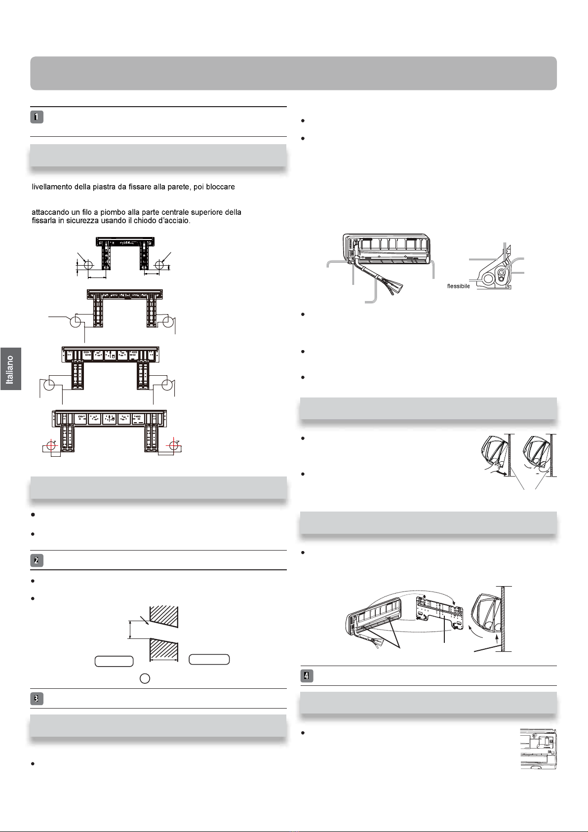
Regolazione della piastra di montaggio e collocazione del foro
●
su parete
1. Eseguire, in base ai pilastri o architravi nelle vicinanze, un appropriato
temporanea-
mente la piastra usando un chiodo d’acciaio.
2. Controllare di nuovo che il livellamento della piastra sia appropriato
piastra, poi
3. Trovare la posizione delforo su parete A/C usando un metro
Fissare una barra di montaggio, venduta separatamente, alla barra late-
●
rale e all’architrave, quindifissare la piastra alla barra di montaggio.
Fare riferimento alla sezione precedente, “Prima installazione della pia-
stra di montaggio”, per la posizione delforo.
Perforamento del muro e in
●
stallazione del coperchio foro tubatura
Fare un buco di 60 mm di diam
●
etro, leggermente inclinato verso la parete
esterna.
Installare il coperchio foro tubatura e sigillarlo con stucco dopo l’installazione
Installazione dell’unità interna
[Tubatura posteriore]
Passare le tubature e il tubo flessibile di scarico, poifissarli con nastro
adesivo
[Sinistra · tubi parte posteriore sinistra]
Se la tubatura è a sinistra, tagliare con una pinza, il coperchio dellatuba
tubatura sinistra.
Se la tubatura è posteriore sinistra, piegare i tubi seguendo la direzio-
ne delletubature verso il contrassegno delforo per la tubatura sinistra
posteriore che è stampigliato sui materiali d'isolamento termico.
1. Inserire il tubo flessibile di scarico nella scanalatura dei materiali d’isola-
mento dell’unità interna.
2. Inserire il cavo elettrico interno/esterno dal retro dell’unità interna ed
estrarlo dal lato frontale, poi collegarli.
3. Coprire la superficie svasata dell’attacco con olio refrigerante e collegare
itubi. Coprire bene la parte di collegamento con materiale d’isolamento e
assicurarsi di fissare con nastro adesivo
Il cavo elettrico interno/esterno e il tubo flessibile di scarico devono esse-
re fissati insieme al tubo per il refrigerante usando del nastro protettivo.
[Tubature con altre direzioni]
Tagliare, con le tenaglie, il coperchio per la tubazione in base alla direzio-
ne della stessa e piegarla in base alla posizione delforo sulla parete.
Quando si piega, prestare attenzione e non spaccare i tubi.
Connettere prima il cavo elettrico interno/esterno, quindi estrarre la parte
connessa all'isolante termico della parte di connessione speciale.
Attaccare in modo sicuro l'unità esterna sulletac-
che superiori della piastra di montaggio. Sposta-
re il corpo da un lato all’altro per verificare che
sia fissato in sicurezza.
Per fissare l'unità sulla piastra di montaggio,
allontanarlo dal lato inferiore e poi appenderlo in
perpendicolare.
Quando si scarica l'unità interna, usare la propria mano per sollevare
il corpo e lasciare la graffa, quindi sollevare la parte inferiore del corpo
leggermente verso l'esterno e sollevare l'unità finché non lascia la piastra
di montaggio.
Collegamento del cavo elettrico interno/esterno
T
●
ogliere il coperchio deiterminali nell'angolo in basso a
destra dell'unità interna, quinditogliere la copertura dei
fili svitando le viti.
Prima installazione della piastra di montaggio
G
Buco della parete
Ø 60 mm
Lato interno Lato esterno
(Sezione delforo su parete) Tubo del foro tubatura
graffa piastra di
montaggio
Tubo
di scarico
Coperchio per
tubatura destra
Coperchio per tubatura
inferiore
Fissare con nastro adesivo
Coperchio
per tubatura
sinistra
Materiale
termicamen-
te isolante
Cavo elettrico interno/esterno
Tubazione
Piastra di
supporto
della
tubazione
Installazione unità interna
Installazione della piastra di montaggio su barra laterale
ed architrave
piastra di montaggio
Schema della tubatura
Fissaggio del corpo dell’unità interna
Scaricamento del corpo dell’unità da interno
Rimozione della copertura dei cavi
6
HSU-09TK1/R32(DB)-IN
HSU-09TK1/R32(DB)-INM
HSU-09TK/R32(DB)-IN
HSU-12TK/R32(DB)-IN
HSU-09TK/R32(DB)-INM
HSU-12TK/R32(DB)-INM
HSU-12TK1/R32(DB)-IN
HSU-12TK1/R32(DB)-INM
HSU-18TK/R32(DB)-IN
HSU-18TK1/R32(DB)-IN
HSU-24TK1/R32(DB)-IN
A=150mm C=120mm
C=113mm
B=
Ø
60mm
A=70mm
B=
Ø
60mm B=
Ø
60mm
B=
Ø
60mm
30mm
45mm
45mm
30mm
35mm
35mm
B=
Ø
60mm
A=120mm C=80mm
A=130mm C=110mm
35mm
35mm
B=
Ø
60mm B=
Ø
60mm
B=
Ø
60mm
This manual suits for next models
10
Table of contents
Languages:
Other HEC Air Conditioner manuals


Popular Air Conditioner manuals by other brands


Carrier
Carrier 38CKC operating guide

Olimpia splendid
Olimpia splendid maeStro Pro Instructions for installation, use and maintenance

Bryant
Bryant Evolution Extreme 186CNV installation instructions

Mitsubishi Electric
Mitsubishi Electric PUZ-ZM200YKA2-ET Service manual

McQuay
McQuay MDB075D owner's manual

York
York PCG4 Series installation manual


