Hedson DRESTER GP 24 User manual

230756 rev 1 ©Hedson Technologies AB 2017
DRESTER GP 24
DE
GB
FR
SE
Technical Manual
Technisches Handbuch
Manuel technique
Teknisk manual

2230756 rev 1
SOMMAIRE
1. Consignes de sécurité................................................91
2. Batterie .........................................................................91
3. Fusibles.........................................................................91
4. Témoin lumineux.........................................................91
5. Remplacement de la carte de contrôle PCD ...........92
6. Menu de configuration...............................................94
7. Mise à jour logicielle...................................................95
8. Remplacement du capteur de température............96
9. Schéma de câblage ....................................................97
10. Régulateur de pression ..............................................99
11. Réglage de la vanne de démarrage progressif.......99
12. Réglage des régulateurs de pression.......................99
13. Réglage des électrovannes......................................100
14. Numérotation et noms des vérins...........................101
15. Capteurs de fin de course sur les vérins ................101
16. Réglage du capot......................................................102
17. Schéma du circuit pneumatique .............................103
18. Réglage du support intérieur ..................................104
19. Réglage de la hauteur du support extérieur du vérin 4105
20. Remplacement de la tête pivotante sur vérin 4 ....105
21. Capteurs de charriot inductifs.................................105
22. Mesure de contrôle du charriot...............................106
23. Installation du palier-bascule sur le charriot..........106
24. Remplacement de la protection de l'arbre............106
25. Rempacement de la pompe....................................107
26. Installation du moteur du mélangeur.....................118
27. Remplacement de l'arbre d'entraînement.............121
28. Autotest ......................................................................126
29. Réinitialisation aux valeurs d'usine .........................132
INNEHÅLL
1. Säkerhetsföreskrifter.................................................135
2. Batteri..........................................................................135
3. Säkringar ....................................................................135
4. Varningslampa...........................................................135
5. Byte av styrkort ..........................................................136
6. Konfigurationsmeny..................................................138
7. Programuppdatering................................................139
8. Byta ut temperatursensorn.......................................140
9. Kopplingsschema......................................................141
10. Tryckvakt.....................................................................143
11. Justering av mjukstartsventilen ...............................143
12. Justering av tryckregulatorerna...............................143
13. Justering av magnetventilerna................................144
14. Cylindrarnas nummer och namn.............................145
15. Cylindrarnas ändlägessensorer...............................145
16. Justera luckan............................................................146
17. Pneumatiskt kopplingsschema................................147
18. Justering av inre vagga ............................................148
19. Justera höjden på cylinder 4 för yttre vagga.........149
20. Byta svänghuvud på cylinder 4 ...............................149
21. Induktiva vagnsensorer ............................................149
22. Kontrollmätning av vagnen......................................150
23. Installation av vagnens gångjärnsförsedda lager .150
24. Byta axelskydd...........................................................150
25. Byta pump..................................................................151
26. Installation av mixermotor........................................162
27. Byta drivaxel...............................................................165
28. Självtest.......................................................................170
29. Fabriksåterställning...................................................176
CONTENT
1. Safety precautions.........................................................3
2. Battery.............................................................................3
3. Fuses ..............................................................................3
4. Warning lamp ................................................................3
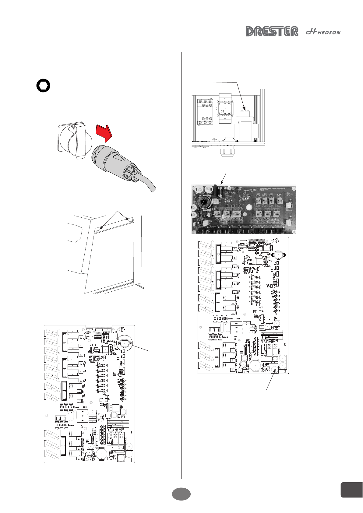
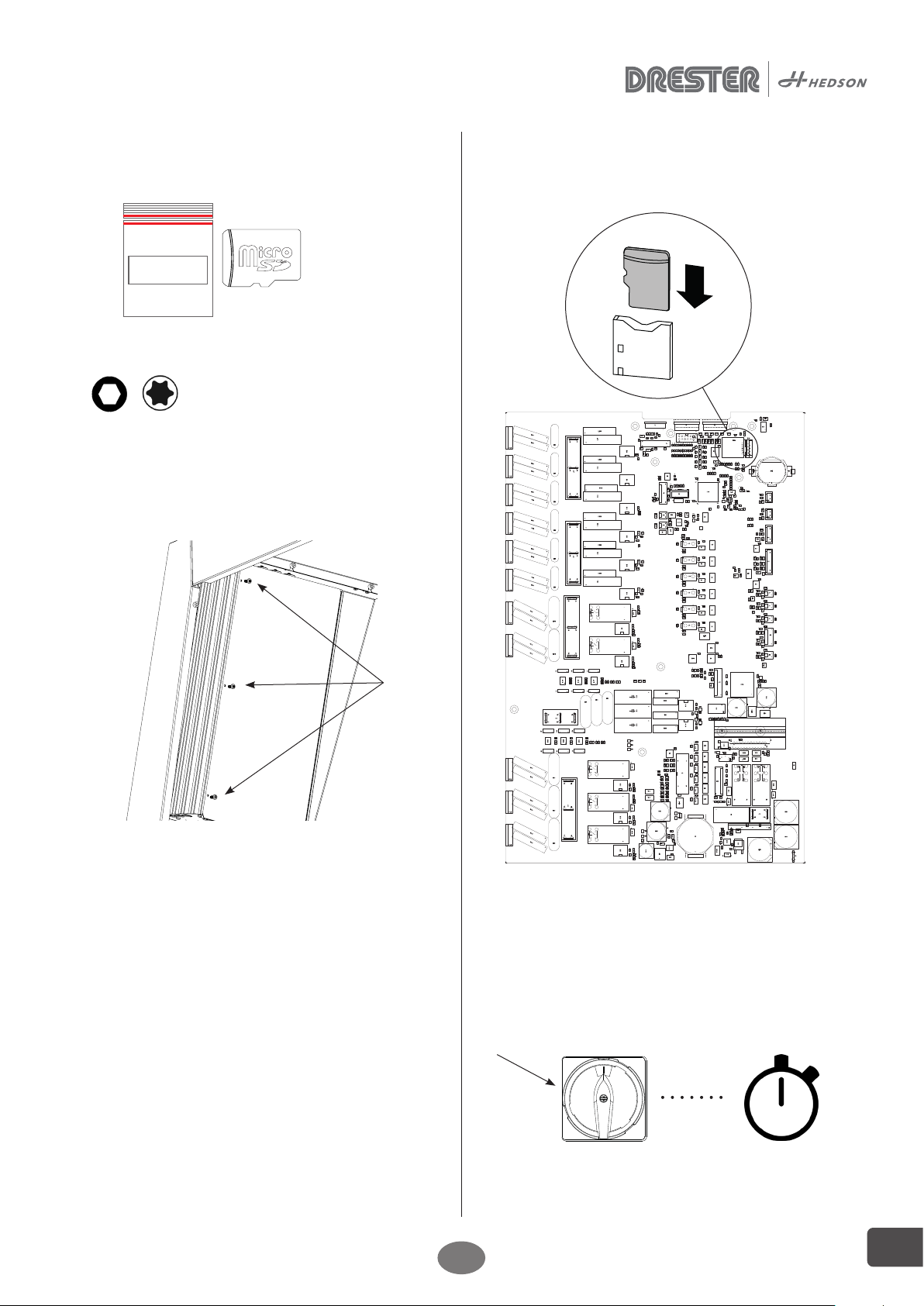
5. Control card PCD replacement................................... 4
6. Configuration menu......................................................6
7. Software update ............................................................7
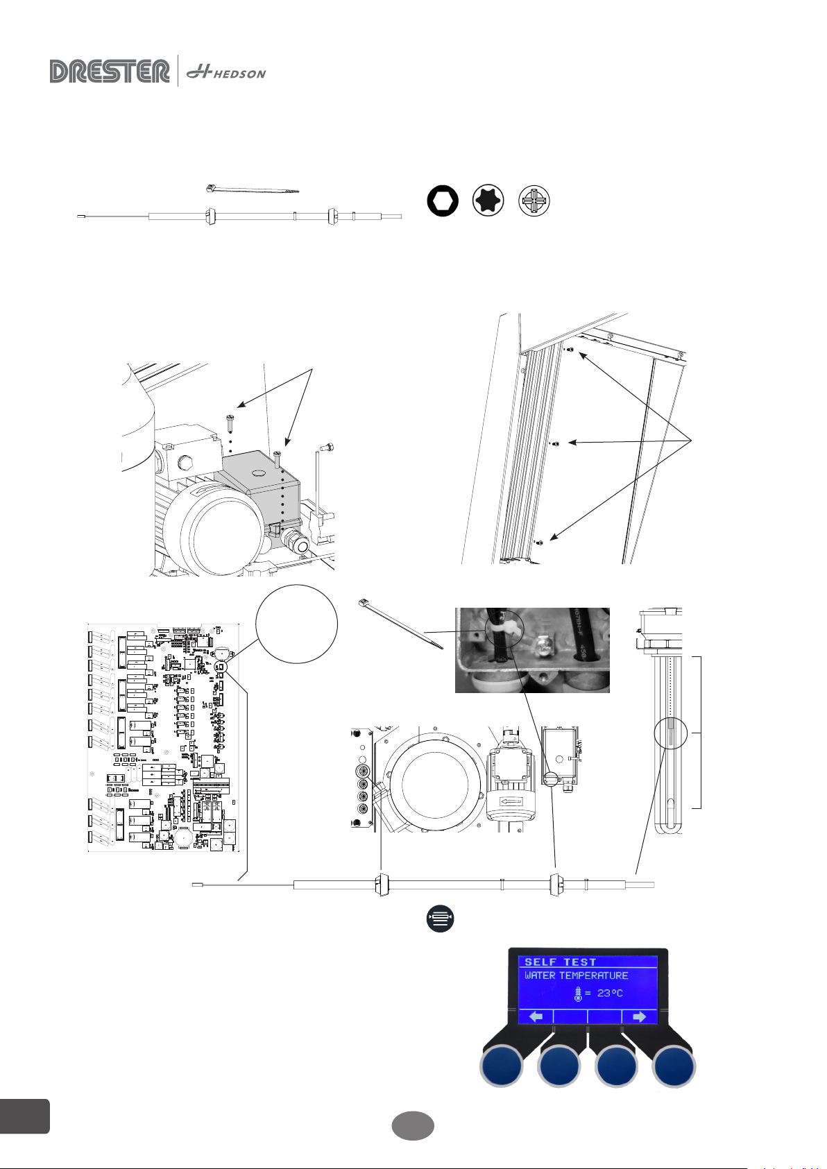
8. Replacing temperature sensor ....................................8
9. Wiring diagram..............................................................9
10. Pressure governor ......................................................11
11. Adjustment of the soft start valve..............................11
12. Adjustment of the pressure regulators.....................11
13. Adjustment of solenoid valves ..................................12
14. Numbering and names of cylinders .........................13
15. End position sensors on the cylinders......................13
16. Adjust the lid................................................................14
17. Pneumatic circuit diagram..........................................15
18. Adjustment of inside cradle.......................................16
19. Adjust the height of cylinder 4 outside cradle ........17
20. Changing swivel head on cylinder 4.........................17
21. Inductive trolley sensors.............................................17
22. Control measurement of the trolley..........................18
23. Installation of the hinged bearing on the trolley.....18
24. Replacing shaft protection.........................................18
25. Pump replacement......................................................19
26. Mixer motor installation..............................................30
27. Drive shaft replacement .............................................33
28. Self test .........................................................................38
29. Factory reset.................................................................44
INHALT
1. Sicherheitshinweise ....................................................47
2. Batterie .........................................................................47
3. Sicherungen.................................................................47
4. Warnlampe...................................................................47
5. Austauschen der Steuerplatine.................................48
6. Konfigurationsmenü ...................................................50
7. Softwareaktualisierung ...............................................51
8. Austauschen des Temperatursensors.......................52
9. Schaltplan.....................................................................53
10. Druckregler..................................................................55
11. Einstellen des sanftanlaufventils................................55
12. Einstellen der druckregler..........................................55
13. Einstellen von Magnetventilen ..................................56
14. Nummerierung und Namen der Zylinder................57
15. Endlagensensoren auf den zylindern.......................57
16. Einstellen des deckels ................................................58
17. Pneumatischer Schaltplan..........................................59
18. Einstellen des innenträgers........................................60
19. Einstellen der höhe von zylinder 4 am aussenträger61
20. Wechseln des schwenkkopfs an zylinder 4..............61
21. Induktive rollwagensensoren.....................................61
22. Kontrollmessung des rollwagens..............................62
23. Installation des scharierlagers am rollwagen ..........62
24. Austauschen des wellenschutzes..............................62
25. Austausch der pumpe ................................................63
26. Installation des Mischermotors..................................74
27. Austauschen der Antriebswelle.................................77
28. Selbsttest......................................................................82
29. Werkseinstellungen ....................................................88
DE
GB FR
SE

3
230756 rev 1 EN
3. Fuses
The machine has three fuses. One fuse is located on top
of the tranformer in the main control box, 500mA 440V
slow fuse.
The second fuse is located in the terminal control box on
the upper left, 3.15A 250V slow fuse.
The third fuse is located on the bottom right of the
control card.
4. Warning lamp
The rating of the lamp is 24 V/5 W.
2. Battery
Battery type is: CR 2032 3V.
1. Safety precautions
1.1 Tools
1
WARNING! Always perform the steps below, before
doing any work on the machine.
Battery
5mm
1. Remove screws and lid.

4230756 rev 1
EN
5.1 Components
5.2 Tools
NOTE: Start instruction with chapter 1 safety precautions
1. Remove screws and lid.
2. Use the special tool to loosen the clips that hold the
circuit board to the aluminum profile.
3. Remove ALL cables for motors, heaters, sensors
etc. Ribbon cables released by pushing the pins
upwards like illustrated on picture. Mark cables for
reassembling.
5mm T20
x 11
1
2
x 11
5. Control card PCD replacement
3

5
230756 rev 1 EN
6. Position new PCB and fasten three screws without
tightening PCB.
NEW PCB
6 (x3)
7. Use the supplied clips to lock the card against the
aluminum profile.
x 11
*CLICK*
8. Fasten ALL cables. Reassemble as previously marked.
Ribbon cables fasten by pushing the pins downwards
like illustrated below and on next page.
8
5. Check that the tape on the aluminium profile is
positioned as shown in picture or replace it.
5
4 (x8)
4. Remove screws and the PCB
7

6230756 rev 1
EN
x 8
10
9
/8.Self test/....
12
9. Tighten all screws.
10. Position lid and fasten screws.
11. Perform Configuration (chapter 6).
12. Perform Self test.
6. Configuration menu
Choose settings according to machine configuration.
+
PIN CODE 1632
VOLTAGE 400V
MACHINE TYPE 24
HEATER INTELLIGENT
CLEAN RINSE NO YES
MIXER MOTOR NO YES
TEMPERATURE °C °F

7
230756 rev 1 EN
NOTE: Start instruction with chapter 1 safety precautions
1. Remove screws and lid.
2. Place sd card in slot.
1
2
15 SEC
4
7. Software update
7.1 Components
x.x.x.
5mm T20
7.2 Tools
3. Assemble in reverse order.
4. Start with main switch, wait 15s, open settings,
navigate to (/7.Version/Model/Sw/x.x.x) and check that
x.x.x correspond with the number on the bag.
5. Repeat instruction to remove sd-card.

8230756 rev 1
EN
½
½
Water
Temp.
Sensor
J19
3
8. Replacing temperature sensor
8.1 Components 8.2 Tools
5mm T20
NOTE: Start instruction with chapter 1 safety precautions
1. Remove screws.
2. Remove screws and lid.
1
/8.Self test/...../Water Temperature/....
5
x 2
3. Disconnect the old temp. sensor and then connect the
new sensor.
4. Assemble in reverse order.
5. Start machine and check that the temp. sensor is
working (/8. Selftest/Water temperature/....).
2

9
230756 rev 1 EN
Page
Next page
Edited by
Source
230584
230584 WW GP24 Lava 400V
MR +
Date
Date Weelwasher LAVA GP24 EU 400V 3~ 16A
1
Modification
0 76
Checked
8 93
2
4
2016-10-10 Hedson Technologies AB
1
2
=
Name
5
Revision
Previous page
THE INFORMATION CONTAINED HEREIN IS PROPRIETARY TO HEDSON TECHNOLOGIES AB
AND IS NOT TO BE REPRODUSED, COMMUNICATED TO A THIRD PERSON, OR USED
WITHOUT THE EXPRESSWRITTEN PERMISSION OF HEDSON TECHNOLOGIES AB.
Supply 400V 3~
16A, 50Hz
LINEAR MOTOR
OUT1
WATER
WHEEL
OUT2
AIR
WHEEL
OUT3
WHEEL
LIFTOUT4
OUT5
WHEEL
FIXING
OUT6
MAIN
CONTACTOR
IN1
DOORIN2IN3
IN4IN6 AIN4
WATERLEVEL
AIN3
MOTOR
POSITION
AIN2
TEMP.
PTC
AIN1
WATER
TEMP.
EXT. I/O
24Vac
PUMP MOTOR HEATER ROTATION MOTOR MIXER MOTORMAIN POWER
BTH1
BATTERY
DIGITAL OUTPUT
DIGITAL INPUTS ANALOG INPUTS
IN5
WHEEL LIFT
Option
Supply Terminal Box Board
COM1
RS485
MODBUS
COM2
RS485
MODBUS
EMERG.
STOP
-U1
Circuit Board LAVA
V2U2W2
W1V1U1
-M2
Rotation Motor
M
3~
V2U2W2
W1V1U1
-M3
Mixer Motor
Option
M
3~
-H1
2.2
Heater
Option
-Y2
24Vdc
Air Wheel Valve
-Y1
24Vdc
Water Wheel Valve. Option
-T1
400/230/24V
Transformer
0 230V
0 24V
400V
L1T1
L2T2
L3T3
20A
-Q1
Main / Emergency stop switch
J30
T1
J30
T2
J43
GND
J25
P1
J25
P2
J25
P3
J29
H1
J29
H2
J26
R3
J26
R2
J26
R1
J27
M3
J27
M2
J27
M1
-M4
Dynamic Arm
M
4
5
6
7
-J23:8
3
2
1
-R1
Motor Position
Feed Back
1
2
3
-J21:4
1
-J7:2
J17:1 J17:2
-J16:2
-J16:1
-J15:2
-J15:1
-J14:2
-J14:1
-J13:2
-J13:1
-J12:2
-J12:1
1
-J8:2
1
-J9:2
1
2
3
-J10:5
4
1
-J11:2
-J19:2
1
-J20:2
1
4
5
-J22:6
3
2
1
-R2
Water
Temp.
Option
4
5
3
2
1
J4
KBD.1
J6
DISPLAY
-U3
Display
-U4
Buttons
4
6
-J18:14
2
1
-J1:6
RS232
10
12
8
35791113
J29
H3
JP1
GND
MSD2
µSD
J45
SWD DEBUG
PE
L3
L2
L1
WH BK BN WH BNBKWH BNBKWH BNBK
12
11
Overheating
Thermostat
Θ
22
21
Θ
32
31
Θ
RD BK YE BU WH
J28
L3
J28
L2
J28
L1
BN
BK
WH
V2U2W2
W1V1U1
-M1
5,5kW
Pump Motor
M
3~
A1
A2
K1
24VDC
1/L1 2/T1 1.2
3/L2 4/T2 1.2
5/L3 6/T3 1.2
1413 1.1
2221
1/L1 2/T1
K1
1.2
3/L2 4/T2
5/L3 6/T3
1 2
S1
Emergency stop
1.2
1.4
1 2
S1
1.2
13
14
K1
1.2
Main
Contactor
J48
KBD.2
U5
LED
1
2
S1
1.2
1-J46:21J47:2
JP2
0V
/2.1
24V
/2.1
RS485-A
/2.3
PE
/2.1
RS485-B
/2.3
PE
PE
PE
9. Wiring diagram

10 230756 rev 1
EN
Page
Next page
Edited by
Source
230584
230584 WW GP24 Lava 400V
MR +
Date
Date Weelwasher LAVA GP24 TBB
1
Modification
0 76
Checked
8 93 4
2016-10-10 Hedson Technologies AB
2
2
=
Name
5
Revision
Previous page 1
THE INFORMATION CONTAINED HEREIN IS PROPRIETARY TO HEDSON TECHNOLOGIES AB
AND IS NOT TO BE REPRODUSED, COMMUNICATED TO A THIRD PERSON, OR USED
WITHOUT THE EXPRESSWRITTEN PERMISSION OF HEDSON TECHNOLOGIES AB.
CYLINDER 1
OUT10
CYLINDER 2
OUT11
CYLINDER 3
OUT12
CYLINDER 4A
OUT13
CYLINDER 4B
OUT14
CYLINDER 5A
OUT15
CYLINDER 5B
OUT16
CYLINDER 6
OUT17
BUZZER
OUT18
Supply Terminal Box Board
24Vac
RS485
MODBUS
F1 Fuse 3,15A
OUT19
AIR VALVE
OUT20
WARNING LIGHT
POS. CYLINDER 1
(-) (+)
POS. CYLINDER 2
(-) (+)
POS. CYLINDER 3
(-) (+)(-) (+)
POS. CYLINDER 4
(MID)
POS. CYLINDER 5
(-) (+)
POS. CYLINDER 6
(-) (+)
IN 23
PRESSURE
IN 24
IND SENS 1
IN 25
IND SENS 2
IN 26
IND SENS 3
-U2
Circuit Board TBB
-Y10
24Vdc
Valve
1
-J13:+24V
Y9
24Vdc
Valve
1
-J14:+24V
Y8
24Vdc
Valve
1
-J15:+24V
Y7
24Vdc
Valve
1
-J16:+24V
Y6
24Vdc
Valve
1
-J17:+24V
Y5
24Vdc
Valve
1
-J18:+24V
Y4
24Vdc
Valve
1
-J19:+24V
Y3
24Vdc
Valve
J48:1
-J20:+24V
Buzzer
+
J18:2
-
J18:1
J24:3 -J24:4
1-J3:2
-J24:2J24:1
+
J23:+24V
-
J23:1
-Y11
24Vdc
Valve
+
J17:+24V
-
J17:1
H2
IN10 2
+J4:1
+3
IN11 4
IN12 2
+J5:1
+3
IN13 4
IN14 2
+J6:1
+3
IN15 4
+J10:1
+3
IN16 2
IN17 4
+5
IN18 6
S3 S4S6
S5
S8
S7
S10
S9 S11
IN19 2
+J11:1
+3
IN20 4
S13
S12
IN21 2
+J12:1
+3
IN22 4
S15
S14
2
0V
J1:3
+24V
1
B1 +-
2
0V
J7:3
+24V
1
B2 +-
2
0V
J8:3
+24V
1
B3 +-
2
0V
J9:3
+24V
1
B4 +-
JP1
0V
/1.1
24V
/1.1
RS485-A / 1.1
PE
/1.1
RS485-B / 1.1

11
230756 rev 1 EN
10. Pressure governor
The pressure governor detects if air supply pressure
drops below 6 bar. This will cause a B-type alarm, see
alarm codes chapter 9 in the user manual. The pressure
governor must not be set to a different value, if broken
it needs to be replaced to maintain the right level of
machine safety.
11. Adjustment of the soft start valve
On the top of the soft start valve there is an adjusting
screw with which you can set how fast the pressure is to
rise. The screw should be tightened down completely
and then loosen 12 turns.
On the rear of the soft start valve there is a red plastic
screw. This should be positioned horizontal.
If uncertain connect the calibration kit 230753 to
cylinder 3.
2. Turn OFF the machine.
3. Disconnect the hose to cylinder 3.
4. To connect the calibration kit, remove the red plug
and connect it as seen in the picture.
5. Turn ON the machine. After ~10 seconds the air
pressure value on the calibration kit is stabilized.
Adjust the regulator if necessary.
The lid regulator for cylinder 3 should be set to 2 bars when
the lid is closed. Regulator is found on the terminal box.
Open and close four turns. (Illustrated on picture below)
pressure governor
adjusting screw
red screw
soft start valve
pressure regulator
air pressure
Open and then close 4 turns.
12. Adjustment of the pressure
regulators
These settings should not be changed. If the regulators
aren´t working properly check the following settings:
The intake air regulator (picture below) should be set to
7.5 bars.
Note: Always decrease pressure and then increase to
wanted level.
1. Turn ON the machine. After ~10 seconds the air
pressure value is stabilized. Adjust the regulator if
necessary. air pressure

12 230756 rev 1
EN
When one or more solenoid valves are changed the flow
restrictors needs to be set properly.
13. Adjustment of solenoid valves
Cyl. 6
4
12 10 14 12
Open and then close 4 turns. 10 7
1113
14
4
Cyl. 5 Cyl. 5 Cyl. 4 Cyl. 4 Cyl. 3 Cyl. 2 Cyl. 1
Tighten the adjustment screw completely, open the
number of turns as indicated in the picture below.

13
230756 rev 1 EN
14. Numbering and names of
cylinders
15. End position sensors on the
cylinders
To set the position of the sensors the machine needs to
be turned ON with the compressed air connected. Start
Self test (see chapter 28) to move the cylinder to correct
position for the sensor that will be set.
1. Place sensor in the slot, slide it left or right until the
LED turns ON.
2. Slide sensor to the right until the LED turns OFF and
remember the location.
3. Slide sensor to the left until the LED turns OFF and
remember the location.
4. Position the sensor in the middle of the two locations
found in step 2 and 3.
Location 1
Location 2
3 Lid
1 Guide Rail
4 Outside cradle
5 Inside cradle
6 Side support
2 Transverse feed

14 230756 rev 1
EN
Aligned with
edge on lid.
Tighten from
below.
3-5 mm
3-5 mm
2-3 mm
Aligned with the
edge of roof.
Tighten
16. Adjust the lid
1. Tighten the hose clamps at the front when the swing is
in the correct position.
2. Tighten the rear hose clamps when the swing is in the
correct position.
3. Stand behind the machine and tighten the right- hand
screw union according to picture.
4. Lift up the left screw union 2-3 mm and tighten the
screws.
5. The upper valve screw should be tightened down
completely and then loosen 1,5 turns. The lower valve
screw should be tightened down completely and the
loosen 6 turns.
upper screw
lower screw

15
230756 rev 1 EN
17. Pneumatic circuit diagram
Cylinder 6
Cylinder 5
Cylinder 4
Cylinder 3
Cylinder 2
Cylinder 1
Water
Air

16 230756 rev 1
EN
157 ±2
18. Adjustment of inside cradle
1. Place the inside cradle in its outer position and with
the help of a piece of straight metal i.e a ruler, measure
between the ruler and the inside cradle, see picture
below. The measurement should be 157 ± 2 mm.
2. If the measurement is incorrect, loosen the nut on the
cylinder rod, see picture below. Then try to adjust the
inside cradle by turning the cylinder rod.
Loosen the nut.
Turn the rod to
adjust the cradle.
3. Check the measurement again. If it´s not possible to
adjust the cradle so the measurement is 157 ±2 mm
in step 2 turn back the cylinder rod and tighten the
nut again.
4. Loosen the four screws and pull out the coupling.
5. Clean the shaft carefully from any grease.
6. Disassemble the coupling and clean all parts.
7. Put a SMALL amount of grease on the surface, stay
3mm inside the edge.
8. Put grease on the threads.
Grease
9. Assemble the coupling, note the direction of the parts.
Note direction of slots
10. Place the inside cradle in its outer position and
measure the distance, 157 ± 2 mm before tightening
the four screws. The screws should be tightened in
order to 14Nm.
1 3
24
ruler
union.
11. Check that the union between the cylinder and
the pin bolt is greased and can move smoothly.
Otherwise it can seize and lock.

17
230756 rev 1 EN
19. Adjust the height of cylinder 4
outside cradle
1. Dock the trolley.
2. Open SELF TEST, see chapter 28
3. Run cylinder 4 and make sure the cylinder hits the
center of the guide.
4. If necessary, adjust the height with the adjuster screw.
Check aligment
Adjuster screw
20. Changing swivel head on
cylinder 4
Secure the swivel head with Loctite 222.
21. Inductive trolley sensors
The machine has 3 inductive sensors that sends signals
about where the trolleys are located during the wash
cycle.
1 2 3
When a sensor detects steel, it sends a signal while the
LED on the back of the sensor is lit.
LED
If the LED on the back of the sensor is lit continuously,
the sensor is defective and should be replaced. The
cable is connected on the left side of the machine, see
picture below.
Connection of
inductive sensor.
Note that the sensor should be installed 1 mm inside the
protective edge.
1
To verify the sensors function perform a Self test, see
chapter 28.
Locking nut

18 230756 rev 1
EN
22. Control measurement of the
trolley
Place the trolley on a level floor and measure from the
floor up to the top of the guide on the trolley.
Max 123mm
Min 115mm
23. Installation of the hinged
bearing on the trolley
1. Install and tighten the nuts lightly and make sure that
there is no gap between the two bearing pieces.
No gap
2. Tighten the nut in the following order:
Nut 1: ¼ turn
Nut 3: ¼ turn
Nut 2: ¼ turn
1
2
3
24. Replacing shaft protection cyl 6
24.1 Components
x 2
24.2 Tools
13mm
NOTE: Start instruction with chapter 1 safety precautions
1. Remove clips.
1

19
230756 rev 1 EN
4
2. Remove screw.
3. Remove and discard gaiter.
4. Cut off the the top of the new gaiter.
2
3
5. Add new gaiter.
6. Assemble in reverse order.
7. Fixate in right position.
8. Add new clips.
5
7
x 2
8
25. Pump replacement
25.1 Components
x 2
x 4
x 8
x 12
LOCTITE
x 4
x 3
8.4x26x1
23x36x1
13x24x2
13x27x1
x 4
x 4
25.2 Tools
x 2
IMPORTANT!
Not included:
Order Spare part: R2892
5mm 6mm 18mm
10mm
8mm
Loctite 5922
OBS: loctite 222 and 8009 not included

20 230756 rev 1
EN
NOTE: Start instruction with chapter 1 safety precautions.
1. Loosen screw.
2. Remove hose.
3. Loosen screw.
4. Remove hose.
13
2
4
Other manuals for DRESTER GP 24
2
Table of contents
Languages:
Other Hedson Washer manuals
Popular Washer manuals by other brands

BALAY
BALAY 3TS872BE Operating instructions and installation

Speed Queen
Speed Queen Top loading Washer owner's manual

White-Westinghouse
White-Westinghouse SWS1233CQ/S owner's guide

Fortress Technologies
Fortress Technologies FJW50A11P user manual

Electrolux
Electrolux EWF12022 user manual

Siemens
Siemens WG44G2Z5NL User's manual and installation