Hegner Multicut-1 User manual
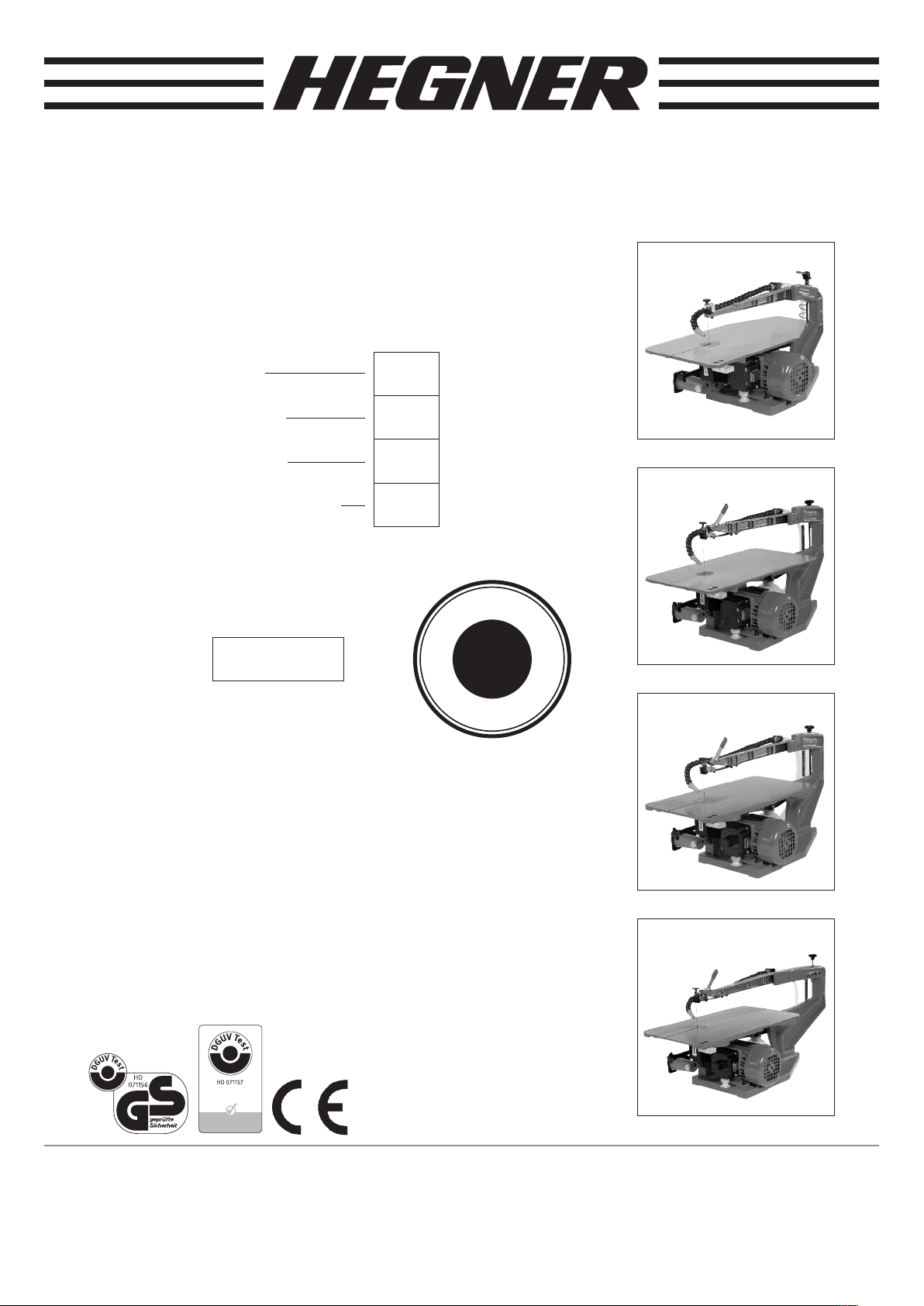
Super- Universal- Fine Cut Saws
riginal operating instructions
Multicut-1
Multicut-2S
Multicut-SE
Multicut-Quick
Serial no.:
Important
In order to prevent the risk of accidents, please
read the operating instructions carefully before
installation and use of the machine.
Always keep these operating instruction
near to the machine.
It is important that these instructions are
always available for reference purposes.
holzstaubgeprü
G
A
R
A
N
T
I
E
G
A
R
A
N
T
I
E
G
U
A
R
A
N
T
E
E
3
J
A
H
R
E
A
N
S
Y
E
A
R
S
*
*Except electronics (1 year)
and wearing parts

EC-Conformity Declaration for
Super-Universal-Fine Cut Saws
Multicut-1
Multicut-2S
Multicut-SE
Multicut-Quick
We declare on our sole responsibility that the product described under
technical data complies with the following conditions:
- 2006/42EC Machine directive
- 2004/108 EC EMC directive
- 2006/95 EC ow voltage directive
The following regulations were applied to the construction and design of the machine.
Harmonised standards:
- EN 12100-1
- EN 12100-2
- EN 294
- EN 349
- EN DIN 61000
- EN 60529
- EN 60204-1
For the machine, a construction test to § 7 of the Machine Safety aw
(GPSG) was performed by the
Trade Association for Wood
Test and Certification Centre in the BG-PRÜFZERT
Vollmoellerstraße 11
70563 Stuttgart
and
GS test certificate number 071156 and
BG test certificate number 071157
were issued.
Hegner Präzisionsmachinen GmbH
upfenstraße 29
78056 VS-Schwenningen
VS-Schwenningen, 12.08.2010
Werner Broghammer
Technical Manager

Preface
Machines: Multicut-1
Multicut-2S
Multicut-SE
Multicut-Quick
are suitable for both professional and private use.
The machines are intended solely for sawing wood,
plastics, NF metals and soft iron with fretsaw blades and
marquetry saw blades with a length of 130 mm.
These operating instructions should provide the necessary
knowledge for installation, commissioning and handling
of the machines.
Furthermore the instructions contain important notes for
your safety when handling the machine, and give tips for
use and repair of faults.
Please read these operating instructions carefully and
in particular note the references and warnings.
Incorrect handling and failure to observe the warning
notes and descriptions in the operating instructions
invalidate any guarantee by the manufacturer of the
machines.
If you have any questions after reading these instructions,
please contact your dealer.
Hegner Präzisionsmaschinen GmbH
Symbols and their Meanings
Text marked with this symbol contains very important
information, including relating to avoidance of health
risks. These texts must be observed.
This symbol points to texts containing comments,
information or tips.
This symbol refers to a chapter, subchapter, page or
diagram. Follow these references to obtain further
information on the current topic.
This point indicates a description of activities which you
must perform.
Wear protective goggles.
Contents:
1.0 Technical data
2.0 Delivery of machine
3.0 Operating instructions
4.0 Proper use
5.0 Safety notes
6.0 Remaining risks
7.0 Unpacking/assembly
8.0 Commissioning/decommissioning
9.0 Changing the saw blade
10.0 Change the saw blade for internal cutting
11.0 Swivelling the table plate
12.0 Adjusting the stroke length
13.0 Extraction connections
14.0 Maintenance/cleaning
15.0 Repair/spare parts
16.0 Type of application
17.0 Selection of speed
18.0 Operating errors and causes
1.0 Technical Data
Multicut-1
Clearance length 365 mm
Clearance height 50 mm
Max. cut height 50 mm
Saw table size 435 x 230 mm, 45º swivel
ength x width 520 x 270 mm
Saw blade stroke 12 and 15 mm
Motor 230 V~, 50 Hz, 100 watt output power
Weight Approx 16 kg net
ength of saw blade 130 mm
Extraction connection Ø 35 mm
Mains fuse 6 A
Multicut-2S and SE
Clearance length 460 mm
Clearance height 65 mm
Max. cut height 65 mm
Saw table size 435 x 230 mm, 45º/12° swivel
ength x width 610 x 280 mm
Saw blade stroke 12 and 19 mm
Motor 230 V~, 50 Hz, 100 watt output power
Weight Approx 19 kg net / 23 kg
ength of saw blade 130 mm
Extraction connection Ø 35 mm
Mains fuse 6 A
Multicut-Quick
Clearance length 560 mm
Clearance height 65 mm
Max. cut height 65 mm
Saw table size 435 x 230 mm, 45º/12° swivel
ength x width 730 x 280 mm
Saw blade stroke 12 and 19 mm
Motor 230 V~, 50 Hz, 100 watt output power
Weight Approx 29 kg net
ength of saw blade 130 mm
Extraction connection Ø 35 mm
Mains fuse 6 A
☞
⇒•
1

1.1 Values for extraction connection
Volume flow for connection Ø 35 mm: 70 m3
Vacuum pressure present
for an air speed of 20 m/s: 1666 Pa.
The dust emissions measured according to the principles
for testing dust emission (workplace-related dust
concentration) from woodworking machines by the Trade
Association for Wood lie clearly below the applicable limit
value o 2,0 mg/m3.
1.2 Noise emission
Measurement conditions:
- prEN 31202 for workplace-related emission values
with the following additions established by TC 142 in
order to obtain an accuracy class of better than 3 dB:
- The ambient correction factor K2A or K3A is < 4 dB.
- The difference between external noise level and the
noise sound pressure level is < 6 dB for each
measurement point.
- K3A is calculated according to appendix A, prEN 31204.
- A square envelope surface with nine measurement
points at a distance of 1 m from the reference surface
was used.
Workpiece: spruce
- Dimensions 150 / 100 / 20 mm (planed all round).
Tool: Fretsaw blade
- Dimensions t = 1.5 mm, b = 1 mm.
- The noise level emitted amounted to:
Sound pressure level at workplace [dB (A)]
Idling: 64.1
Cutting: 74.5
A measurement uncertainty supplement of K = 4 dB (A)
applies to the said emission values.
The values given are emission values and therefore do not
necessarily equate to safe workplace values. Although
there is a correlation between emission and immission
levels, it cannot be reliably deduced whether or not
additional precautionary measures are required. Factors
which can influence the immission level present at the
workplace at any time include the duration of effect, the
nature of the workplace, other noise sources etc., e.g. the
number of machines and other adjacent processes. The
reliable immission level may also vary from country to
country. This information should however enable the user
to make a closer assessment of the risk and danger.
2

2.0 Delivery of machine
• After receiving the machine please check:
- packing for damage (inform carrier immediately in case
of damage).
- completeness of content according to delivery note.
- examine the packing for sundry parts.
3.0 perating instructions
Read the operating instructions precisely before
commissioning and use of the machine. No guarantee
is given in the case of incorrect handling and failure to
follow the operating instructions.
4.0 Proper use
- The machine is designed solely to cut wood, plastics,
NF metal and soft iron using fretsaw blades and
marquetry saw blades with a length of 130 mm.
- Only cut workpieces which are securely supported
and can be guided.
- No further or different use is intended.
- The machine may only be used, fitted and maintained
by people familiar with it and aware of the risks.
- The relevant accident prevention regulations and other
generally acknowledged health and safety rules must be
observed.
- Only original spare parts may be used.
- The manufacturer is not liable for any damage caused
by use of non-original spare parts.
- Changes to the machine or incorrect use of the
machine exclude the manufacturer’s liability for
damage.
5.0 Safety notes
5.1 General safety notes
- Keep unauthorised persons away from the machine.
- Only allow children to work on the machine under
supervision.
- Do not touch any moving parts with fingers.
- Wear protective goggles.
3
5.2 Commissioning
- Check that the voltage on the motor rating plate
corresponds to the voltage from the power source.
- Connect the dust extractor.
⇒ Point 13.0
- Only work in ventilated areas.
5.3 Users
- Read the operating instructions to prevent specific
machine accident risks.
- Never work under the influence of drugs, alcohol or
medication.
- Wear tight fitting clothing and protective goggles.
- Do not wear jewellery when working.
5.4 Before starting work
- Check that the machine is switched off.
⇒ Point 8.3
- Check that the saw blade fitted is suitable for the work.
- Check that the saw blade is clamped tightly.
- Check that all protective devices are fitted.
5.5 During work
- Remove residue and cuttings only when the machine is
switched off.
- On power failure, set the on / off switch to O.
5.6 After work
Switch off the machine and remove the plug.
6.0 Remaining risks
Even on proper use and despite observation of all
relevant safety regulations, because of the design
required for the purpose of the machine, the following
remaining risks can still arise.
- Touching the fretsaw blade.
- Breakage of fretsaw blade.
- Contact with live parts if there is damage to
- terminal box
- capacitor, or
- exposed supply cables.
- Inhalation of dust harmful to health.

7.0 Unpacking / Assembly
7.1 Unpacking
⇒
Fig. 7-1
• ift the machine out of the packing box as shown.
• Do not lift by the upper swing arm.
7.2 Assembly
⇒ See Fig. 7-2
• Place the machine on a stable vibration free support so
that it can be controlled from the front.
- The height of the support should be adapted to the size
of the operator and depends on whether operation is
performed seated or standing.
• Attach the machine.
- either with 2 wood screws inserted from above through
the two holes (1) in the subframe (or with 2 coach bolts),
- or with 3 M8 bolts screwed from below into the threaded
bore (2) through the machine stand.
7.3 Environment
The location of the machine should be free from
- vibration
- moisture
- free from aggressive gasses and vapours
- free from mineral dust and
- able to be ventilated.
7.4 Electrical installation
The electrical installation of the site must comply with the
relevant regulations and meet the requirements of the
machine.
⇒1. Technical data
• Activate the mains switch so that the machine is
switched off.
⇒ point 8.3 switching off the machine.
• Connect the plug to the socket.
Route the power cable so that
- it does not hinder work
- it does not constitute an obstacle for tripping and
- it is not kinked, crushed or damaged.
4
Fig. 7.1
Fig. 7.2
12
12
2

8.0 Commissioning/Decommissioning
8.1 Commissioning the machine
We assume
- that you have read the previous chapters (in particular
Chapter 5, Safety instructions). If not, please do so and
return to this point.
- that the machine is properly assembled, installed and
connected.
- that all tools or workpieces are removed from the
working area.
- that all parts of the machine are undamaged and
correctly mounted.
• Check whether the saw blade fitted is straight.
A bent saw blade is unusable and must be replaced
with a new one.
⇒9. Changing the saw blade.
8.1.1 Tensioning the saw blade
⇒ Fig. 8-1 and 8-2
• Check that the clamping lever (1) is in the clamping
position.
• Tensing the saw blade using the cross-handled
screw (2) (Multicut 2S / SE / Quick).
On Multicut 1, tighten the saw blade with the clamping
lever (1).
• To do this turn the cross-handled screw or clamping
lever (Multicut 1) clockwise until the saw blade emits
a high note when tapped with the finger.
8.1.2 Releasing the saw blade
⇒Fig. 8-1 and 8-2
• Ensure that the machine is switched off before
releasing the saw blade.
• Release the saw blade by pulling the quick release
lever (1) forward (Multicut SE / Quick).
On Multicut 1, push the clamping lever up.
8.1.3 Connect vacuum cleaner
⇒ Fig. 8-1 and 8-2
• Connect the suction nozzle of the vacuum cleaner to
the opening provided (3).
• Make sure that the protective cover (4) is lifted up
☞
5
Fig. 8-1
Fig. 8-2
Multicut 2S/ SE / Quick
Multicut-1
21
1
34
34
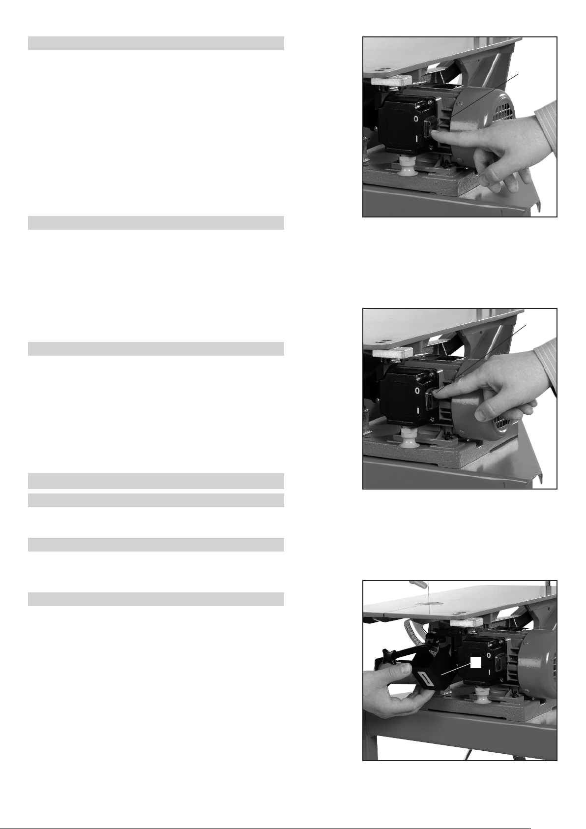
8.2 Switching on the machine
⇒
Fig. 8-3
Warning:
The machine starts to work as soon as it is switched
on.
• First remove all tools, workpieces, residue and
chippings from the working area.
• Connect the plug to the socket and switch the
machine on with the power switch (1) by pressing the
rocker switch down (I).
• Switch on the vacuum cleaner.
8.3 Switching off the machine
(for brief interruptions)
⇒ Fig. 8-4
• Switch off the machine with the power switch (1) by
pressing the rocker switch up (O).
• Switch off the vacuum cleaner.
• Remove all tools, workpieces, residue and chippings
from the working area.
8.4 Decommissioning the machine
(for longer stoppages, change-over, end of work etc.)
•Switch off the machine with the power switch (1) by
pressing the rocker switch up ( ) and remove the
plug from the socket.
• Release the fretsaw blade.
• Remove all workpieces, residue and chippings from the
working area.
9.0 Changing the Saw Blade
9.1 Switch off saw
⇒8.4 Decommissioning the machine.
9.2 Release saw blade
⇒8.1.2 Release saw blade.
Also release the saw blade if the blade is broken.
9.3 Fold protective cover down
⇒ Fig. 9.1
• Fold protective cover (1) down.
• Also remove chippings and residue from the protective
cover.
6
Fig. 8-3
Fig. 8-4
Fig. 9-1
1
1
1

9.4 Remove saw blade from machine
⇒
Fig. 9-2
• Turn the knurled screw up until it only just projects
through the bottom of the saw blade holder.
⇒ Fig. 9-3
• Gently press the upper swing arm down and remove
the saw blade clamp from its holder.
⇒ Fig. 9-4
• Press the clamp retaining spring down slightly and
remove the entire saw blade with clamps from the
machine.
9.5 Remove saw blade from saw blade clamps
⇒ Fig. 9-5
• Place the saw blade clamp in the clamp insert device
at the front right of the saw table.
⇒ Fig. 9-6
• Using the square wrench, open the clamps until you
can remove the saw blade.
9.6 Clamp new saw blade in saw blade clamps
⇒ Fig. 9-5
• ay the new saw blade in the clamps, precisely
centred and straight, with the teeth pointing down to
the right.
• Push the saw blade up to the stop (on the square bolt)
and then retract it approx 1 – 2 mm (so that the bolt
does not twist the blade when it is tightened).
• Clamp the saw blade clamp tightly using the square
wrench.
⇒ Fig. 9-7
• Clamp the other end of the saw blade in the same
way.
⇒ Fig. 9-8
• Ensure that the saw blade ends are clamped centrally.
9.7 Insert saw blade with clamp in machine
⇒ Fig. 9-4
• First insert the lower clamp in the lower swing arm.
• Then insert the upper clamp in the upper swing arm.
⇒ Fig. 9-9
• Turn the upper knurled screw towards the clamp so
that a gap of around 1 mm exists between the clamp
and the bolt.
☞
7
Fig. 9-2 Fig. 9-3
Fig. 9-4 Fig. 9-5
Fig. 9-6 Fig. 9-7
Fig. 9-8 Fig. 9-9

10.0 Changing the saw blade for int. cutting
To make an internal cut in a workpiece with the
machine, the workpiece must have an opening in which
you can insert the saw blade. We recommend using the
special clamp for internal cutting.
10.1 Decommission the machine
⇒ 8.4 Decommissioning the machine.
10.2 Fit the special clamp
⇒ Fig. 10-1
• Attach the special clamp in the upper swing arm and
lock with the knurled screw.
10.3 Insert the workpiece
• Push the saw blade to one side until you can guide
the saw blade through the opening of the workpiece.
10.4 Clamp the saw blade
⇒ Fig. 10-2
• From the front, guide the saw blade into the special
clamp, ensuring that the blade does not bend.
• Close the special clamp by twisting the knurled
aluminium screw.
10.5 Tensioning the saw blade
⇒ 8.1.1 Tensioning the saw blade
• Align the workpiece so that when the machine is
switched on, it cannot be touched by the saw blade
and flung out.
Note: When using the special clamp, the knurled
screw must always be locked in position on the top
arm. This will save time when changing the blade.
11.0 Swivelling the table plate
By adjusting the table plate, you can make angled cuts
up to maximum 45º on workpieces.
11.1 Decommission the saw
⇒ 8.4 Decommissioning the saw.
11.2 Swivel table plate
• Turn the table insert (1) Fig. 11-1-1
• Turn the cross-handled screw (2), Fig. 11-1-2,
around one turn anticlockwise.
• Angle the table plate to the required position and
retighten the cross-handled screw.
☞
☞
☞
8
Fig. 10-1
Fig. 10-2
Fig. 11-1-1
Fig. 11-1-2
1
2

12.0 Adjusting the stroke length
The machine is set by the factory to a long stroke length
which is normally best for most fretsaw work.
For working in extremely thin, light material such as
wood veneer or thin sheets, shortening the stroke may
improve saw control and smoothness. There is less risk
of breaking the thin fretsaw blade.
12.1 Decommission the machine
⇒ 8.4 Decommissioning machine.
12.2 Unscrew protective cover
⇒ Fig. 12-1
• Using the Allen key, unscrew the bolt (1) and remove
the protective plate.
12.3 Lock the cam
⇒ Fig. 12-2
• Push the steel pin (1) into the bore on the cam plate.
12.4 Release the connecting rod
⇒ Fig. 12-3
• With one hand hold the steel pin (1). This prevents
the cam plate turning.
• Using the fork wrench (3) (on Multicut 1, Allen key 3
mm) turn the screw (2) anticlockwise.
12.5 Adjust the stroke length
⇒ Fig. 12-4
• Push the connecting rod (1) aside. Behind this are the
two threaded bores in the shaft of the cam plate.
• For a short saw stroke,
- screw the bolt into the threaded bore closest to the
centre point (3).
- For a long saw stroke, screw the bolt into the threaded
bore further out.
12.6 Clamp the connecting rod
⇒ Fig. 12-5
Before screwing on the connecting rod ensure that the
spacer (1) is fitted.
• When tightening the connecting rod again, secure the
cam plate against twisting with the steel pin.
☞
☞
9
Fig. 12-1
Fig. 12-3
Fig. 12-4
Fig. 12-5
Fig. 12-2
1
1
3
2
1 3 4
1

13.0 Extraction connection
Certain wood types such as chipboards etc.
produce harmful dust emissions during machining.
For this reason the machine must be connected to
a dust extractor. For long and frequent use of the
machine, operating measures must ensure that the
extractor is automatically switched on when the
machine is switched on.
13.1 Connection
⇒ Fig. 13-1
The machine is designed for a standard dust extractor
(vacuum cleaner).
Push the connector of the extractor system into
opening (1) of the connection piece so that it locks.
13.2 Adjust the upper extraction
⇒ Fig. 13-2
• Adjust the upper extraction hose (1) so that it lies on
the workpiece around 5 mm away from the saw blade.
If however you want to work without the extractor, the
cut line can be blown clear by pulling the hose (4) off
the connection piece (5) and inserting it in the pump
base (3).
When the dust extractor is not connected, the
machine may only be used for open air work. In
closed rooms the dust extractor must be connected
(see 13.0 Extraction connection).
14.0 Maintenance / Cleaning
The machine is low maintenance.
Only the upper and lower arm bearings need to be oiled
regularly (approx. every 10 operating hours) with a fine
non-resinous oil (e.g. sewing machine oil).
14.1 Maintenance – oil arm bearings
⇒ Fig. 14-1
• Remove any dust deposits at the lubrication points.
• Using a light oil, oil both arm bearings (1). Apply 3 to
4 drops of oil at the points marked with arrows
(between the swing arm and washer).
The clamping spindle (2) must not be oiled or
greased.
☞
☞
☞
☞
10
Fig. 13-1
Fig. 13-2
Fig. 14-1
1
1
3
1
1
2
4
5

14.2 Maintenance – inspection
• With the machine switched off, carry out a visual
inspection at regular intervals and check the parts
of the machine for damage, above all
- the plug
- the power cable
- the terminal box
• If damage is found in particular to the electrical
equipment, decommission the machine
immediately and arrange for professional repair
with original spare parts.
14.3 Cleaning
- Clean the machine according to the level of dirt.
- No deposits of dust or chippings should form on or in
the machine.
14.3.1 Decommission machine
⇒ 8.4 Decommissioning the machine
14.3.2 Clean the machine
• Clean the machine by extracting the dust with a
vacuum cleaner.
• Remove the side protective cover from time to time
and remove any dust below it.
• Remove sticky deposits with a brush or similar.
• Do not use any
- flammable
- aggressive or
- scouring cleaning agents
• Prevent the penetration of fluid / liquid into the
machine and in particular the electrical parts.
• If however moisture or fluid enters the machine,
do not connect the machine to the power supply.
• In this case contact the dealer or manufacturer.
15.0 Repair / Spare parts
These operating instructions do not contain any repair
instructions. Parts are repaired and / or replaced at
your own risk.
• The following notes must be observed.
15.1 Repair
• Do not repair any (faulty) electrical machine parts.
• These parts must be replaced by original spare
parts from the manufacturer.
• nly the manufacturer or authorised dealer /
specialist with corresponding training (e.g.
electricians) may replace electrical machine parts.
• If incorrect D.I.Y. work is performed on electrical
machine parts, there is a risk of life-threatening
current surges and/or burns.
• The person responsible is liable for all damage or
injury caused in this way.
Faulty or worn machine parts:
- may in principle only be replaced by the manufacturer
/ authorised dealer or specialist with corresponding
training.
- may be replaced by the user with original parts from
the manufacturer if the user has the necessary
mechanical knowledge.
- The person responsible is liable for injury and/or
damage caused by incorrect repair or replacement
work by the user or other unauthorised persons.
If you still wish to repair your machine yourself:
• first disconnect the power switch and remove the plug
from the socket.
☞
☞
11

16.0 Tips for use
16.1 Examples of correct choice of saw blade
⇒ Table on side protection cover of machine
Important:
Blunt saw blades must be replaced. This applies in
particular when cutting iron. Full cutting power and
accuracy is achieved only if the recommended quality of
saw blade is used.
Useful note:
If for economy reasons you wish to continue to use a
blunt saw blade, for example for cutting iron, attach a
smooth support approx. 20 mm thick to the saw table
plate of the machine using twin-sided adhesive tape,
and continue to cut on this. By raising the saw table in
this way you can progressively use up more of the saw
blade.
Working with plastics:
To prevent the material melting when cutting, mask off
the cutting line with plastic adhesive tape.
16.2 Feed pressure
The feed pressure to be exerted on the workpiece must
always be directed obliquely from top to bottom, else
the workpiece may jump. Some workpieces require a
strong feed pressure.
16.3 Stop
In general stops are not used when sawing with
fretsaw blades. Fretsaw blades will move off the
cutting line if the workpiece is force-guided.
Accurate sawing requires:
- a sharp saw blade
- a thin, accurate cutting line
- correctly applied, bright light
16.4 Straight cutting
• Always hold the workpiece at an angle of 1 to 5º (the
angle depends on material, saw blade type and blade
tension).
16.5 Notes on sawing metal
• First deburr metal workpieces to be cut on all sides
and flatten these off carefully so they sit flat.
• Either glue thin or small workpieces (e.g. thin sheets)
onto a 5 mm thick plywood block (using contact
adhesive or twin-sided adhesive film) or place these
between two pieces of plywood and secure against
slipping with pins.
• Then cut the workpiece out together with the plywood
(do not choose sheets that are too thick).
• Use
- fretsaw blade no. 1 to 5 for
- soft NF metals, e.g.
- aluminium (sheet)
- soft copper (sheet)
- soft brass (sheet)
If necessary you can also use metal saw blades
numbers 5 to 9.
• Before sawing, coat the cut line with lubricating oil
(universal oil).
• Use
- metal saw blades nos. 1, 5, 9 or 12 for
- hard NF metals e.g. for
- hard aluminium (sheet)
- hard copper (sheet)
- hard brass (sheet)
- iron (sheet).
• Before sawing, coat the cut line with cutting oil or
paste.
• Despite using saw blades of top quality, depending on
hardness iron will cause greater blade wear.
17.0 Speed selection
(only on motors with electronic speed control)
• In general, low speeds are better if accuracy,
guidance of the saw blade or durability of the saw
blade are important, whereas higher speeds are
generally better for higher working output and reduced
cutting times.
•Thin or fragile materials are best handled at low speeds.
• Extra thick materials or plastics are best handled at
medium or low speeds.
☞
☞
☞
☞
☞
☞
12

13
18.0 perating Mistakes and Causes
Effect
Workpiece catches or
jumps.
Sawblade does not
appear to cut well.
Sawblade pulls out of
clamp.
Sawblade running hot
and burning or tearing.
Hard to follow marked
lines.
Cutting face is bowed.
Cutting face is not
vertical.
Underside of
workpiece splinters.
Cause
To much feed pressure on the workpiece.
Sawblade is in the machine upside down.
Turning a sharper radius than the sawblade
will comfortably allow at the feed speed.
Blunt or wrong sawblade.
Poor quality sawblade.
Insufficient feed pressure.
Clock key screw insufficiently tightened.
Too strong a feed pressure, turning too
quickly in thick timber.
Too fine a sawblade in close grain timber.
Blunt sawblade.
Too strong a feed pressure.
Blunt or incorrect grade of sawblade.
Not enough support on this materials.
Insufficient blade tension.
Blunt sawblade and too strong a
feed pressure.
Too fine a sawblade.
Table top not a 90°- to the blade or table
adjustment screw not tightened.
Wrong type of sawblade.
Worn table insert.
Remedy
Slaken off the pressure. Give the blade time
to cut at its own speed.
Put blade in correctly (see 9.5).
Slow down, ease the sawblade slowly round
tight corners.
Replace with sharp and/or correct sawblade!
Use high quality German sawblades!
Increase feed pressure.
Increase clamping pressure! If the sawblade
continues to pull out - replace clamp.
Reduce feed pressure!
Choose coarser sawblade!
Replace sawblade.
Reduce feed pressure!
Replace sawblade or choose finer blade!
Back thin sheet with a 4 mm plywood or
hardboard sheet.
Increase blade tension!
Replace with new sawblade and decrease
feed pressure!
Utilise a coarser sawblade!
Align table top correctly with a square and
tighten screws!
Utilise reverse tooth sawblades!
Change table insert!
(included with standard accessories)
14
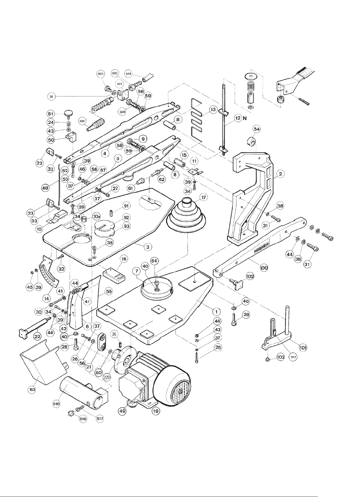
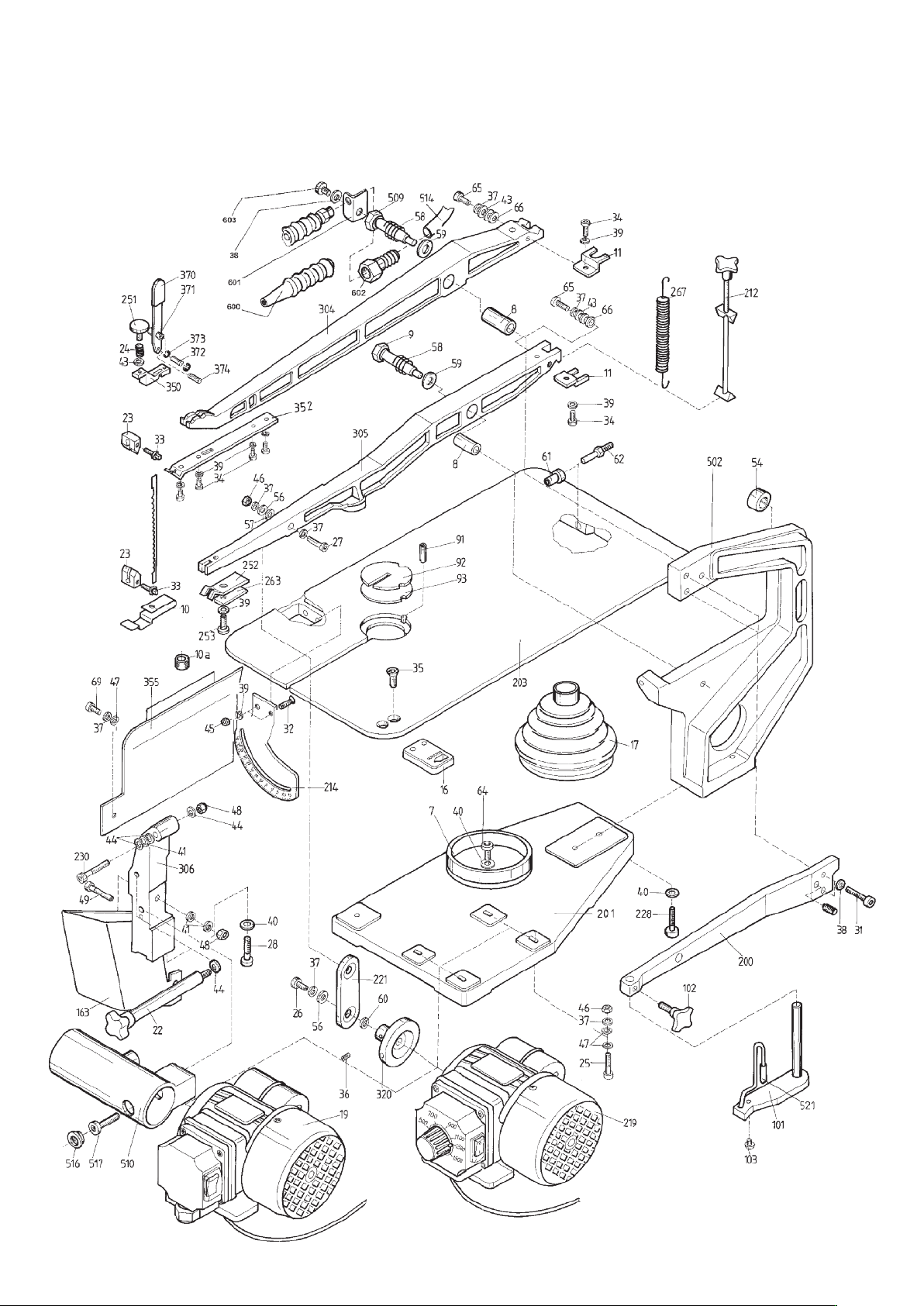
Spare parts
If you require a spare part, simply quote the
number shown in the exploded drawing.
HEGNER Multicut-1
15
HEGNER Multicut-2S

16
HEGNER Multicut-SE

17
HEGNER Multicut-Quick

11/2010
This manual suits for next models
3
Table of contents
Other Hegner Saw manuals


Popular Saw manuals by other brands


woodmizer
woodmizer 1996 LT25 Safety, Setup, Operation & Maintenance Manual

Hyd-Mech
Hyd-Mech H10A Safety and operating instructions

Delta
Delta 20-330 instruction manual

woodmizer
woodmizer LT40 Series Safety, Setup, Operation & Maintenance Manual

Powerplus
Powerplus POWX225 manual

Power Fist
Power Fist J1G-355C owner's manual

Delta
Delta UniSaw 36-L31 instruction manual

Nova gear
Nova gear NG-210 instruction manual

woodmizer
woodmizer LT40L AH Safety, Setup, Operation & Maintenance Manual

woodmizer
woodmizer LT15 AL-KO Safety, Setup, Operation & Maintenance Manual

ESAB
ESAB Aristo 1000 instruction manual

Mac allister
Mac allister MTSP800A manual