manuals.online logo
Brands
  1. Home
  2. •
  3. Brands
  4. •
  5. helivol
  6. •
  7. Toy
  8. •
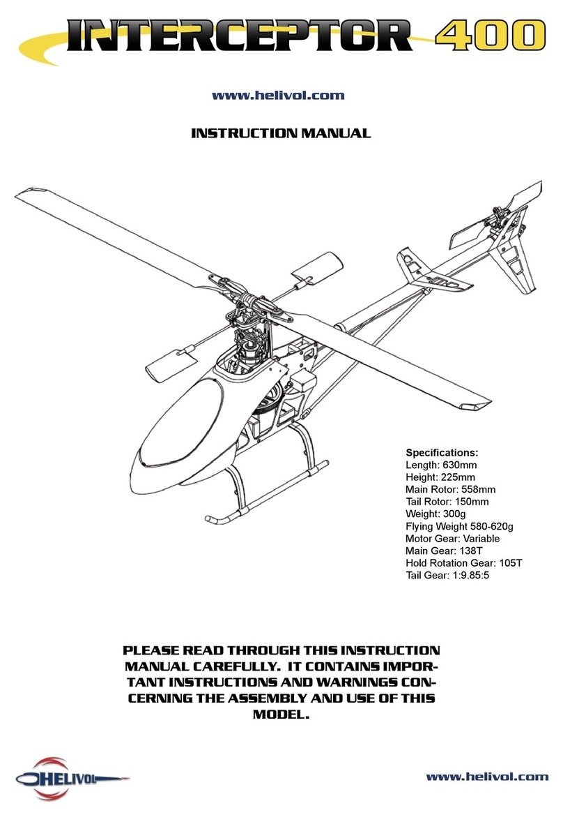
  9. helivol Interceptor 400 User manual

helivol Interceptor 400 User manual

B
u
i
l
d
G
u
i
d
e
2
We will start with the head assembly.
This is the contents of the bag.
This is the assembly order of the Blade
Holders (INT-003).
Over view of the entire head assembly. The M3 Nylon Nut (INT-007) followed by
the Bearing (INT-005), Bearing Collar
(INT-006) & the last Bearing. These are
put on the Feathering Spindle (INT-010).
Push through Blade Holders (INT-003). Once in place slide on Spindle Bush (INT-
009).
3
Take four O Rings (INT-008). Place two on either side of the Centre
Hub CNC (INT-004).
Put the Bearings (INT-005) into place fol-
lowed by the Collar (INT-006).
Insert Feathering Splindle (INT-010) and
place Spindle Bush (INT-009) on opposite
side. Place second Blade Holder (INT-
003) over Feathering Spindle (INT-010).
Place the last Bearing (INT-005). Place the Nylon Nut (INT-007) on to end.
4
Tighten with two 5.5mm socket wreches. Assemble ball links (INT-001 + INT-002).
Attach Ball Links to Blade Holders (INT-
003).
Screw two 3mm screws into each Blade
Holder.
That is the blade grips completed.
5
Next is assembling the Stabilizer Control
Arm Set (INT-018).
Assemble the ball links (INT-001 + INT-
002) and screw them on to the Mixing
Arms (INT-017) - note position.
Place Collar (INT-011) into CNC Centre
Hub (INT-004) and push Seesaw (INT-
016) into place.
Screw another two ball links (INT-001 +
INT-002) into place on Stabilizer Control
Set (INT-018).
Screw Seesaw (INT-016) into place from
both sides with Pan Head Screw (INT-
012) .
Screw both Mixing Arms (INT-017) onto
the Seesaw (INT-016) through a Bearing
Spacer (INT-013) and two Bearings (INT-
014) with a Pan Head Screw (INT-015).
6
Position the Stablizer Control Set (INT-
018).
Push the Stabilizer Bar (INT-019)
through the Stabilizer Control Set (INT-
018) and Seesaw (INT-016) and into
position.
Centre the Stabilizer Bar (INT-019) with
an equal length on each side of the
Stablizer Control Set (INT-018).
Insert grub screws (threadlock metal on
metal xings) into Stabilizer Control Set
(INT-018) to lock Stabilizer Bar. Put Sta-
bilizer Blades (INT-020) on.
Check that the Stabilizer Blades (INT-
020) are level with the Stabilizer Control
Set (INT-018).
Apply threadlock to grubscrew and x
into place.
7
Ensure that all the Ball Links (INT-001
+ INT-002) are correctly tted to the
Swashplate Set (INT-023).
The Main Mast (INT-026) may require
cleaning to remove residue - please en-
sure that it is smooth.
Insert Needl Pin (INT-028) into Washout
Control Arm (INT-029) - note orientation
of part.
Assembly order of Washout Control Arm
(INT-029).
Push Bearing (INT-014) into place. Put Collar (INT-011) on opposing side
and screw into place the Ball Link (INT-
001 + INT-002).
8
Screw Washout Control Arm (INT-029)
into place on Slide Block (INT-031).
Please ensure screw is aligned correctly.
DO NOT OVERTIGHTEN.
Repeat assembly of Washout Control Arm
(INT-029) and afx to the other side of
the Slide Block (INT-031).
One length from the engraved edge is
longer than the other. The longer side is
to be placed into the frame of the heli-
copter. The shorter length into the head.
Insert the shorter side of the Main
Mast (INT-026) into CNC Centre Hub
(INT-004) and x with Pan Head Screw
(INT025) and M2 Nylon Nut (INT-024).
Slide Washout Control Set onto the Main
Mast and align with pins - please note
the direction the washout is inserted.
Slide Swashplate (INT-023) on the the
Main Mast and clip the Radius Arms(INT-
030) on to the inner Swashplate (INT-
023).
9
Place the Mast Lock (INT-027) onto the
main shaft and lightly fasten it in place
with the grub screw. That is the head
completed.
Next up is the Tail Drive.
Push the head of the Counter Shaft (INT-
036) into the Counter Gear Case and
secure with an E ring(INT-037).
Insert Bearings (INT-034) into the Coun-
ter Gear Case (INT-035).
Push the second Counter Gear Case
(INT-035) onto Counter Shaft (INT-036).
Place Drive Pulley (INT-033) onto the end
of the Counter Shaft (INT-036) and place
cap on end.
10
Place washer (INT-032) followed by a Ny-
lon Nut (INT-024) - do not over tighten.
Next is the Auto Rotation Gear Set (INT-
041).
Insert Autorotation Drive Shaft (INT-042)
into Autorotation Gear (INT-043) - it
should click into place.
Place Main Gear with one way bearing
(INT-040) on top of the Autorotation
Gear (INT-043).
Put the collar on top the one way bear-
ing. Put to one side in a safe place along
with nut and bolt.
Push bearings into the correct blocks
(INT-038).
11
Screw ball links (INT-001 + INT-002) into
the elevator arm (INT-048)
Take rear boom holder (INT-050) and put
into place on frame. Note single slot fac-
ing downward.
Position forward boom holder - note
position of notch on the left side of the
frame.
Take one self tapping screw (INT-047)
and afx through the top mount.
Use another tapping screw to afx the in-
ner boom holder.
Place the tail drive like so.
12
Afx with three self tapping screws at the
above points.
Place bearing holders so that the bearing
faces upward and the recess is downward
(applies for both upper and lower).
Afx both bearing holders in place with
self tapping screws.
Screw into place with tapping screws the
radius arm stay set (INT-045) - note the
direction it faces.
Screw into place the canopy mounts -
afx both left and right sides to either
frame (will not be accesible once frame is
assembled).
Place elevator shaft (INT-051) into holder
on frame.
13
Screw into place the Cross Member (INT-
052) with a Pan Head Screw (INT-012)
use threadlock to secure.
Fix the sides of the frame together -
work from the back. Using the Pan Head
Bolt (INT-053) and M2 Nut (INT-044) -
don’t tighten.
The Aileron Levers (INT-059) need to
have the ball links (INT-001 + INT-002)
attached to them as above.
Complete the frame by matching up the
relevant screws to thier opposites. Reme-
ber to use threadlock on metal to metal
xings.
Elevator Torque Lever (INT-054) also
needs the ball links (INT-001 + INT-002)
installed.
Take one Collective Pitch Lever (INT-057)
and push one Flush Head Screw (INT-
056) through and into an Elevator Mount
(INT-055). Like above.
14
Install the assembled Aileron Levers and
secure with an M2 Nylon Nut (INT-024).
Do not overtighten.
Repeat for both sides. Note direction of
arms.
Place the servo mount with the at edge
up ward and afx to one side with Tap-
ping Screws (INT-047).
Next you need these two washers.
Place the washers over the end of the
Elevator Shaft (INT-051).
Place the Collective Pitch Lever and x
through the central hole with a Pan head
Screw (INT-012) be careful with the
threadlock.
15
This is to be inserted into the frame and
xed through the Collective Pitch Lever
(INT-057).
Push the Elevator Lever into the xed
Collective Pitch Lever. The longer part
should extrude past the lever.
Fix into place the Elevator Lever (INT-
048) with a Washer (INT-032) and a Pan
Head Screw (INT-012).
Screw the Collective Pitch Lever into
place on the opposite side - note ball link
xing. Remeber to use thread lock on the
Elevator Shaft tting (INT-051).
Fix the Elevator Torque Lever (INT-054)
to the Elevator Arm (INT-048) with
Washer (INT-032) and Pan Head Screw
(INT-012). Place washer between lever
and screw
That is the upper frame completed. Well
done!
16
Take Cross Member M2x34 (INT-063)
and insert through the Gyro Mount (INT-
060).
Afx the Lower Frame Set (INT-065) to
the the Cross Member on both sides us-
ing a Pan Head Screw (INT-012) thread
lock is advised.
Fit the Motor Mount (INT-061) with Pan
Head Screw (INT-067) and M2 Nut (INT-
044) with thread lock.
Next is to screw the Battery Mount (INT-
062) into place with Pan Head Screws
(INT-012) and M2 Nuts (INT-044) - the
nuts are on the outside of the frame.
Now to mount the upper frame. Start-
ing at the front take one Cross Member
M2x16 (INT-052) and hold between up-
per frames.
Place a long Pan Head Screw M2x14
(INT-066) through the frame and slide a
Cross Member M2x8 (INT-064) onto it.
17
Screw into place - remember to use
threadlock on metal to metal ttings.
Repeat for other side.
Carry out the same procedure for the
two rear ttings of the frame.
Once complete the upper frame should
be securely attatched to the lower frame
like above.
To make up the skids place the uprights
with the larger gap between its mounts
on rst as they they x to the front of
the frame.
Slide the rear uprights on last.
18
Fix through the frame with Tapping
Screws (INT-047) - note that you x
from the inside of the frame.
Fix the rear of the skids with another
Tapping Screw (INT-047) but screw from
the outside in.
Your Interceptor 400 should now look
like this.
Start the tail by assembling the rotor
holders.
Afx ball links (INT-001 + INT-002) to
the Tail Blade Holder (INT-073)
Push Bearings (INT-014) into Tail Blade
Holders (INT-073).
19
Fix both Tail Blade Holders (INT-073)
onto the Tail Housing (INT-074) with a
Cap Screw (INT-072).
Screw the Tail Rotor Blades into place
with a Pan Head Screw. Note direction
of the blades in comparison with the ball
links. Blades should not be tight.
Screw into place Ball Link (INT-001 +
INT-002) - note position.
On to the Tail Drive Gear Box.
Push Bearings (INT-034) into Tail Unit
Case Set (INT-078) - on both sides.
Place gear cap onto the end of Tail Shaft
(INT-079).
20
Insert Tail Shaft (INT-079) into Tail Unit
Case Set (INT-078) and loop Timing Belt
(INT-081) over gear.
Put Guide Pulley (INT-080) into place
before closing shut the Tail Unit Case Set
(INT-078).
Screw the Tail Unit Case Set (INT-078)
together as above.
Slide Tail Pitch Set (INT-076) onto Tail
Shaft (INT-079) - note direction of t-
ting.
Insert brass collar into Tail Pitch Lever
(INT-077) and follow with screw.
Screw Tail Pitch Lever (INT-077) onto
Tail Unit Case Set (INT-078) at the point
shown above. Clip on to ball link of Tail
Pitch Set (INT-076).

Other manuals for Interceptor 400

1

Other helivol Toy manuals

helivol Interceptor 400 User manual

helivol

helivol Interceptor 400 User manual

Popular Toy manuals by other brands

Pro Boat Motor Lifeboat owner's manual
Pro Boat

Pro Boat Motor Lifeboat owner's manual

Stevens Aero Model microMAX 103 Build instructions

Stevens Aero Model

Stevens Aero Model microMAX 103 Build instructions

V-tech Talk & Go Farm Rattle user manual
V-tech

V-tech Talk & Go Farm Rattle user manual

Air Hogs Thunder Strike Instruction guide

Air Hogs

Air Hogs Thunder Strike Instruction guide

PLAYTIVE JUNIOR TOY WORKBENCH Assembly and Safety Advice

PLAYTIVE JUNIOR

PLAYTIVE JUNIOR TOY WORKBENCH Assembly and Safety Advice

V-tech Kidizoom Lightning McQueen Digital Camera user manual

V-tech

V-tech Kidizoom Lightning McQueen Digital Camera user manual

Tyco R/C Batcycle owner's manual

Tyco R/C

Tyco R/C Batcycle owner's manual

KNEX MARIO KART WII MARIO AND YOSHI FINISH LINE BUILDING... manual

KNEX

KNEX MARIO KART WII MARIO AND YOSHI FINISH LINE BUILDING... manual

V-tech SWITCH&GO DINOS Riot the T-Rex Parents' guide

V-tech

V-tech SWITCH&GO DINOS Riot the T-Rex Parents' guide

V-tech SmartVille - 1-2-3 Treehouse user manual

V-tech

V-tech SmartVille - 1-2-3 Treehouse user manual

V-tech Winnie the Pooh Call  n Learn Phone user manual

V-tech

V-tech Winnie the Pooh Call n Learn Phone user manual

Spinmaster nickelodeon PAW PATROL KT1508WM owner's manual

Spinmaster

Spinmaster nickelodeon PAW PATROL KT1508WM owner's manual

V-tech Go Go Smart Wheels Car Carrier user manual
V-tech

V-tech Go Go Smart Wheels Car Carrier user manual

Top R/C Hobby Geebee R3R Operation manual

Top R/C Hobby

Top R/C Hobby Geebee R3R Operation manual

KNEX SUPER MARIO 3D LAND BOWSER'S CASTLE 38530 manual

KNEX

KNEX SUPER MARIO 3D LAND BOWSER'S CASTLE 38530 manual

V-tech Go! Go! Cory Carson Freddie's Firehouse Parents' guide
V-tech

V-tech Go! Go! Cory Carson Freddie's Firehouse Parents' guide

V-tech Hammer Fun Learning Truck user manual
V-tech

V-tech Hammer Fun Learning Truck user manual

Step 2 8539 manual

Step 2

Step 2 8539 manual

manuals.online logo
manuals.online logoBrands
  • About & Mission
  • Contact us
  • Privacy Policy
  • Terms and Conditions

Copyright 2025 Manuals.Online. All Rights Reserved.