helivol Interceptor 400 User manual

PLEASE READ THROUGH THIS INSTRUCTION
MANUAL CAREFULLY. IT CONTAINS IMPOR-
TANT INSTRUCTIONS AND WARNINGS CON-
CERNING THE ASSEMBLY AND USE OF THIS
MODEL.
www.helivol.com
Specications:
Length: 630mm
Height: 225mm
Main Rotor: 558mm
Tail Rotor: 150mm
Weight: 300g
Flying Weight 580-620g
Motor Gear: Variable
Main Gear: 138T
Hold Rotation Gear: 105T
Tail Gear: 1:9.85:5
INSTRUCTION MANUAL
www.helivol.com

2
IntroductIon..................................2
EssEntIal EquIpmEnt.....................3
BuIld GuIdE..................................5-12
opEratIonal procEdurEs...........13
parts lIst...................................13-14
rotor HEad dIaGram....................15
swasHplatE dIaGram...................16
FramE dIaGram..............................17
FramE assEmBly dIaGram...........18
taIl dIaGram..................................19
lInkaGEs dIaGrams.................20-21
warranty........................................23
The Interceptor 400 is an aerobatic capable
helicopter, offering the performance and y-
ing abilities of 30 - sized nitro helicopter but
within a smaller package.
This is not a toy helicopter. It features a
double-dampened head, belt-driven tail
rotor and aluminium frame. This is a real
helicopter that is more than ready to y any-
where that you can nd a safe landing.
Take care when assembling the Interceptor
400. Incorrectly aligned parts will restrict
the helicopter’s abilities when performing
the extreme aerobatics it has been de-
signed for.
For the latest technical updates or manual
corrections please visit the Helivol website
at www.helivol.com.
warnInG
Strict pre-ight inspections are mandatory
for real aircraft. Although the R/C helicopter
is small and can be own with relative ease,
it does not differ from real aircraft in that if it
were to hit a person or object it could cause
serious damage and/or injury.
If an accident were to occur during opera-
tion the pilot would be held responsible.
Therefore it is recommended that users
possess remote control insurance. Details
on different schemes are available from
your local model shop or online.
Always be sure to inspect the helicopter
before any ight for any signs of damage or
wear. If the helicopter is own in a degrad-
ed condition it is possible for a catastrophic
failure to result.
Immediately replace any part that appears
worn or damaged.
Helivol © Copyright 2009
MADE IN TAIWAN
www.helivol.com

3
Transmitter
Receiver and Servos (3 Collective, 1 Tail)
Gyro
Battery and Charger
Motor
Electronic Speed Controller
Tools:
Pitch Gauge Blade Balancer
Ball Link Pliers Cross Wrench
Allen Wrench
Philips Screwdriver
Box Drive 4mm
Equipment needed:

4
cHoosInG your EquIpmEnt:
The INTERCEPTOR 400 is an impressive
kit helicopter but it requires additional com-
ponents to be operational. You will need
four servos, a radio transmitter and receiver,
a gyro, ESC, motor and lipo battery. We
have carried out substantial tests on various
setups and congurations.
radIo EquIpmEnt
This helicopter requires at minimum a 6CH
transmitter and receiver. It must have the
ability to setup a mechanical mix function on
a 90 degree swashplate. However we rec-
ommend that your radio transmitter also has
the capacity to programme multiple throttle
and pitch curves.
sErVos
We have tested a wide range of servos for
this model. We recommend Acer-Lab A8-
SG. They are fast analogue servos that can
be used with an Alien command. They are
also a perfect t for the frame. Please note
that digital servos can not be used in con-
junction with the Alien Command.
Gyro
You can use any high quality heading hold
gyro with this helicopter. Check compatibil-
ity with your radio equipment.
BattEry
The INTERCEPTOR 400 requires a Lipo
with a capacity of between 1500-2200mAh
and a minimum discharge of 15C for basic
hovering. This helicopter runs on 11.1v (3
Cell’s). Flight time will be between 7-12 min-
utes depending on ight conditions.
The maximum size battery the INTERCEP-
TOR 400 can hold is:
Width: 32.5mm
Height: 28.0mm
Length 104.0mm
Anything larger than this will not t in the
frame and canopy! A well tted battery
makes ying much easier.
motor
We recommend a Acer-Lab Brushless Mo-
tor. This will deliver the power needed to
get the most from the INTERCEPTOR 400
but you can use any motor within the range
2800-3500kv with a suitable pinion.
Esc
We recommend the Acer-Lab 40A. It is
fully programmable and features a double
heatsink, plug and play functionality. It also
boasts a 2 year warranty against defects in
material and workmanship. Any other qual-
ity ESC will also work.
cHarGEr
The battery used for this helicopter will
require a charger for a 3 Cell (11.1V) lipo
battery.

5
Measure the ybar so that is it equal on
both sides of the head. Approx 60mm on
each side.
Thread lock the screws into place then
attach the paddles ensuring that they run
parallel with the head.
BuIld GuIdE:
The INTERCEPTOR 400 is a kit helicopter
this guide covers the INT-401 ARF. In this
section we will take you through the process
to ensure that you correctly assemble your
model. This is a general guide only we rec-
ommend consulting individual component
manuals to ensure correct conguration and
installation. For a complete and thorough
guide on assembly along with videos and
the latest tips and upgrades please visit -
www.helivol.com
assEmBlInG tHE FramE & HEad
The head for the INTERCEPTOR 400
comes assembled in the ARF kit. You need
will need to install the ybar and paddles.
Remove the retaining screw and insert the
ybar.

Place the washer onto the collar of the
main gear. Insert the main shaft through
the frame and into place.
Place the main gear into the frame and
push the shaft through - the washer should
be facing up. Once in place align the holes
in the gear and shaft and t the bolt and nut
use loctite to secure.
Please check that the collar on the main
shaft is secure and correctly holds the head
assembly in place.
skIds
Assemble skids - the uprights with the wider
attachments points are located at the front.
Screw the uprights into place and align the
skid tubes.
6

Align the hole on the end of the boom with
the plastic pin inside the tail rotor assembly.
It will clip into place and hold rm.
Slide the tail push rod holder on to the
boom. Check that the belt is not twisted.
Insert boom into frame aligning the lip with
the groove.
Boom
You will need to feed the belt through the
boom.
We recommend taping the tail push rod to
the belt and then dropping it through the
boom before drawing through the belt after
it.
7

In order to easily place the belt over the
gear it is recommended that you unscrew
the bolt and screws on the boom holder. It
is then possible to push the boom further
into frame.
In order to align the belt correctly - using a
screwdriver rotate the belt 90° anti clock-
wise.
Then slip it over the gear.
Pull the boom back through and into place.
This should result in optimum belt tension.
To test the tension apply pressure onto one
side of the belt. It should not be so tight
as to not move and should not be so loose
as to touch itself. If adjustment is required
move the boom forward or back appropri-
ately. Tighten the boom holder screws once
the boom is correctly positioned.
Boom supports & taIl FIns
Insert rear aluminium rear spacer. Assemble
the boom supports and screw into place on
the spacer - on both sides. Use thread lock.
Screw the other end of the boom supports
into place on the horizontal tail n bracket.
Cut out horizontal n decal and stick to n.
Afx horizontal tail n to the bracket - use
a drop of thin CA to secure the ends of the
boom supports.
8

Cut out vertical tail n decal and stick
into place. Screw vertical tail n onto tail
mount.
Slide tail push rod through the holders on
the boom.
Screw on ball link and clip into place on tail.
InstallInG tHE motor
Attach a suitable pinion to motor shaft, use
a drop of thread lock on the grub screw.
Screw the motor into place on the helicop-
ters frame - use a drop of thread lock on the
mounting screws.
One mounting hole is elongated so as to
allow adjustment. The mesh of the gears
should crimp but not tear a piece of paper
when the gears are turned.
9

InstallInG Gyro, Esc and rX
We recommend installing your gyro and re-
ceiver inside the frame to ensure adequate
protection. Make sure they are easily ac-
cessible for adjustment and conguration.
Once your receiver is securely placed you
can route your wires carefully across the
frame of the INTERCEPTOR 400 ensur-
ing that they clear of all moving parts and
secured rmly with cable ties. The placing
and wiring is dependent on the components
you choose to use on your helicopter.
The ESC can be placed on the bottom or
side of the frame. Whichever is accessible
and within reach of the battery bay. Do not
cable tie into place - use adhesive foam.
InstallInG sErVos
Screw servos into place - don’t attach the
servo arms. Install the aileron servo rst.
Next install the pitch servo using the plastic
servo nuts to secure it into place. Bent nose
pliers can be useful at this point.
Install the elevator servo next.
The tail servo can be tricky so we recom-
mend placing the plastic servo nut onto the
servo prior to mounting as it can make it a
little easier.
10

Attach the servo arms to the elevator and
aileron servos at 90° once their neutral
points have been set. Then connect the
push rods. At this point the swashplate
should be completely at. Consult the dia-
gram on page 22.
The aileron servo should pull the swash-
plate to the left when the cyclic stick on
your radio is moved left. The elevator
servo should pull the swashplate to the
right when the cyclic stick is moved to the
right. If the direction is incorrect rectify us-
ing servo reverser settings/switches.
Set your transmitters throttle to 50% then
attach the pitch servo arm and connect
the push rod. When you now increase the
throttle on your radio the pitch servo should
pull down and the swashplate should rise.
conFIGurInG sErVos
Check that push rod lengths match the dia-
gram on page 21. Connect all the arms to
the relevant ball links (see page 22 for com-
plete diagrams). The links can be easily
pushed into place if you use a small socket
driver.
We recommend disconnecting the motor
from the ESC when conguring the servos.
Congure your radio swash settings to ‘1
SERVO’ or ‘90°’ depending on your radio in-
terface. Connect the battery to your ESC in
order to check servo operation and congu-
ration. Ensure all your trims and sub trims
are initially set to default.
11
Conguring the tail servo requires installing
the servo arm with its neutral point set at an
approximately 90° angle to ensure that the
correct pitch is set for the tail blades.
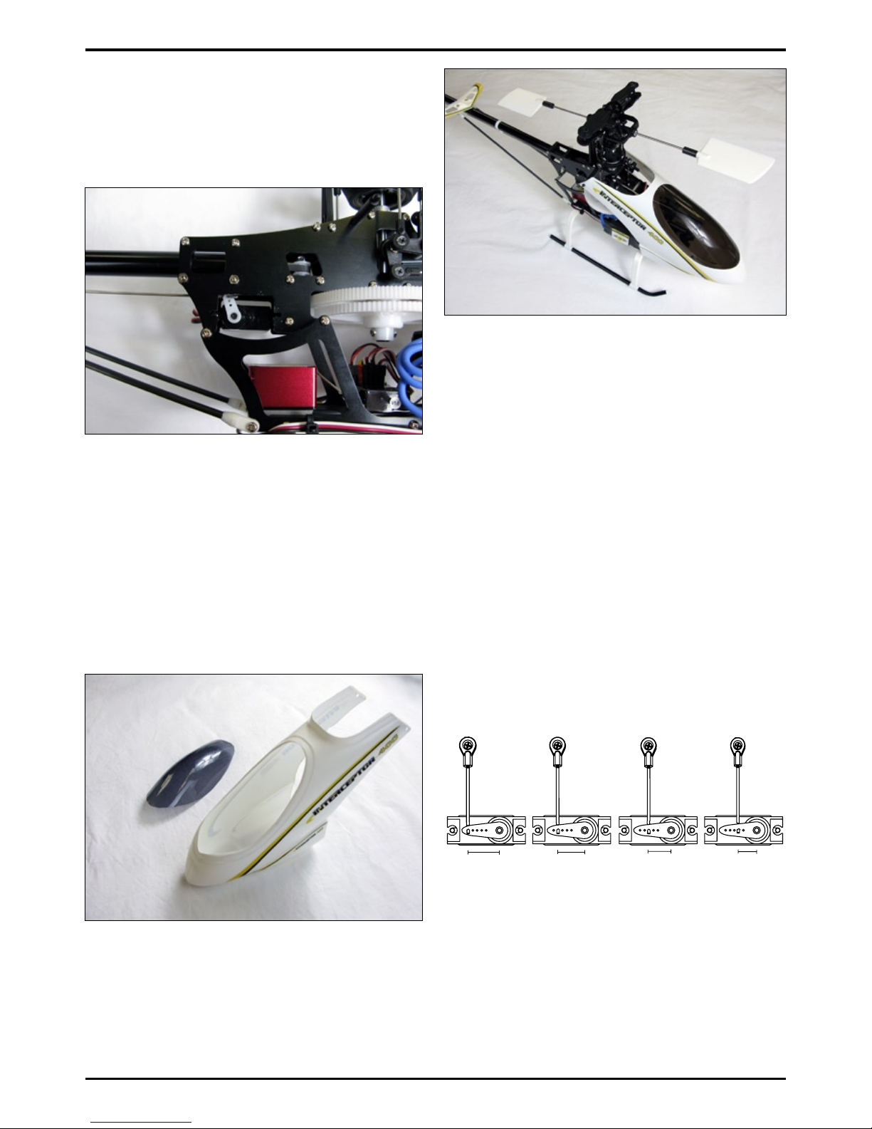
canopy
It is crucial that you install the window of
the canopy - without it the mechanism will
be restricted.
First cut the window out of the canopy and
trim the ashing from the edges. Trim the
shield around the moulding so that it ts the
window.
Fit the shield to the window with the screws
supplied. Ensure the trim on the upper
edge is trimmed down so as to allow a suit-
able t for the swashplate mechanism.
Apply the decals as desired. Fit to the heli-
copter. If you nd the canopies t is too tight
use a hair dryer to warm the plastic before
gently moulding back to suitable shape.
BladEs
Balance your blades using a blade bal-
ancer. Attach them - they should be tight
enough in the grips to hold their position
when moved, but can still be moved easily
by hand.
To set the pitch of the blades adjust the po-
sitioning of the push rod on the pitch servo
arm. The distance dictates the level of pitch
the blades have set. Use this rough guide
to set the pitch correctly in conjunction with
a pitch gauge.
That completes the conguration and as-
sembly of the INTERCEPTOR 400. Please
follow guidelines for the individual compo-
nents regarding installation and setup. You
can nd lots more advice, guides and tips
on our website:
12
13mm = ± 13° Pitch 10mm = ± 10° Pitch 8mm = ± 8° Pitch 7mm = ± 7° Pitch
www.helivol.com

13
BEForE startInG a FlIGHt:
1. Pay attention to your surroundings:
Do not y the helicopter in strong winds, •
rain or at night.
Do not y the helicopter near roads, rail-•
ways or electrical lines.
2. Pre-ight checks:
Before starting always check to ensure•
that there is no damage to any part and
that model responds and operates cor-
rectly.
Always be sure to check that all the mov-•
ing parts are correctly positioned and
that all nuts bolts are suitably tightened.
Please ensure that the batteries for your•
transmitter as well as your helicopter are
fully charged and operational.
wHIlst In opEratIon:
1. Always disconnect the battery when:
adjusting parts on the helicopter or trans-•
mitter.
attaching or replacing parts.•
any unusual noises or vibrations occur.•
if any other potentially dangerous situa-•
tions could occur.
2. When connecting the battery please ob-
serve the following procedures:
Be sure that the transmitters throttle is in•
its lowest position.
Ensure the idle up function is disen-•
gaged.
aFtEr a FlIGHt:
1. Inspect parts immediately. If any screws
seem loose or are missing be sure to re-
place or ret. If cracks or damage are
apparent please replace the components.
parts lIst:
modEls:
INT-400 INTERCEPTOR 400 KIT
INT-401 INTERCEPTOR 400 ARF
sparEs:
INT-001 Flush head screw M2x7
INT-002 φ5 Ball with stand
INT-003 Blade holder
INT-004 Center hub CNC
INT-005 Brg φ3xφ8x4 ZZ
INT-006 Bearing collarφ3xφ5x4
INT-007 M3 nylon nut
INT-008 O-ring P3
INT-009 Spindle bush
INT-010 Feathering spindleφ3
INT-011 φ2 Collar with stand
INT-012 Pan head screw M2x4
INT-013 Bearing spacer 2x3x1.5
INT-014 Brg φ2xφ5x2.5 ZZ
INT-015 Pan head screw M2X10mm
INT-016 Seesaw (L)
INT-017 Mixing Arm (L)
INT-018 Stabilizer control set
INT-019 Stabilizer bar
INT-020 Stabilizer blade
INT-021 Set screw M3x3
INT-022 φ2.6 Bail radius pin
INT-023 Swash plate set
INT-024 M2 nylon nut
INT-025 Pan head screw M2x12
INT-026 φ5 Main mast
INT-027 φ5 Mast lock
INT-028 Needle pin 1.5x7
INT-029 Wash-out control arm
INT-030 Radius arm
INT-031 Slide block
INT-032 FW φ2xφ4x0.3T
INT-033 Drive pulley 11T
INT-034 Brg φ3xφ8x3 ZZ
INT-035 Counter gear case
INT-036 Counter gear 21T
INT-037 E-ring E-2.5
INT-038 Bearing block
INT-039 Brg φ5x11x5 ZZ
INT-040 Main gear 138T (w/one way bearing)
INT-041 Auto-ratation gear set
INT-042 Auto-rotation drive shaft
INT-043 Auto-rotation gear 105T
INT-044 M2 nut
INT-045 Radius arm stay set
INT-046 Cabin cross member
INT-047 Tapping screw M2x6
INT-048 Elevator lever
INT-049 Upper frame set (w/bearing)
INT-050 Tail boom holder
INT-051 Elevator shaft
INT-052 Cross member M2x16

14
INT-053 Pan Head Screw 2x21mm
INT-054 Elevator torque lever
INT-055 Elevator mount
INT-056 Flush head screw M2x15
INT-057 Collective pitch lever set (w/bearing)
INT-058 Servo mount
INT-059 Aileron lever
INT-060 Gyro mount
INT-061 Motor mount set
INT-062 Battery mount
INT-063 Cross member M2x34
INT-064 Cross member M2x8
INT-065 Lower frame set
INT-066 Pan head screw M2x14
INT-067 Pan head screw M2x5
INT-068 Skid set
INT-069 servo nut plastic (10pcs)
INT-070 Main rotor blade
INT-071 Tail rotor blade
INT-072 Cap screw M2x6
INT-073 Tail blade holder
INT-074 Tail housing
INT-075 Tail pitch plate set (w/bearing)
INT-076 Tail pitch set (w/bearing)
INT-077 Tail pitch lever set
INT-078 Tail unit case set
INT-079 Tail shaft (w/pulley 11T)
INT-080 Guide pulley (w/bearing)
INT-081 Timing belt
INT-082 Tail stabilizer set
INT-083 Tail boom
INT-084 Tail boom brace set
INT-085 Rudder control rod
INT-086 Pitch rod
INT-087 Mixing arm rod
INT-088 Stabilizer control rod
INT-089 Pitch rod=L29
INT-090 Elevator lever swash rod
INT-091 Aileron rod
INT-092 Elevator rod
INT-093 M1.2 Rod end
INT-094 Canopy
INT-095 Windshield
INT-096 Motor main gear 15T (3.17 mm)
INT-097 Motor main gear 14T (3.17 mm)
INT-098 Motor main gear 13T (3.17 mm)
INT-099 Motor main gear 12T (3.17 mm)
INT-100 Motor main gear 11T (3.17 mm)
INT-101 Motor main gear 10T (3.17 mm)
INT-102 Motor main gear 9T (3.17 mm)
INT-103 Motor main gear 8T (3.17 mm)
upGradEs:
For an up to date and complete list of all of the upgrades
please visit:
powEr EquIpmEnt:
AL-A8SG ACER-LAB A8SG Servo
AL-D12MG ACER-LAB D12MG Servo
AL-3000KV ACER-LAB Brushless Motor 3000 KV
AL-40A ESC ACER-LAB 40A ESC
www.helivol.com

15
Stabilizer blade and stabilizer control arm must
be assembled so that they are parallel to one anotherr.
o
X
INT-001
INT-002
INT-003
INT-004
INT-005
INT-006
INT-007
INT-010
INT-009
INT-008
INT-011
INT-012
INT-016 INT-013
INT-014
INT-015
INT-017
INT-018
INT-002
INT-001
INT-019
INT-020
INT-021

16
INT-002
(Int-023)
INT-022
INT-001
INT-023
INT-024
INT-025
INT-026
INT-021
INT-027
INT-031
INT-011
INT-029
INT-028
INT-014
INT-001
INT-002
INT-015 INT-030
INT-024
INT-032
INT-033
INT-034
INT-036
INT-037
INT-035
INT-038
INT-026
INT-027
INT-039
INT-040
INT-041
INT-042
INT-043
INT-044
INT-025

17
INT-045
INT-044
INT-046
INT-047
INT-048
INT-002
INT-001
INT-049
INT-050
INT-038
INT-039
INT-052
INT-051
INT-053
INT-012
INT-012
INT-054
INT-055
INT-056
INT-012
INT-047
INT-057
INT-058
INT-032
INT-012
INT-002
INT-001
INT-047 INT-012
INT-059 INT-024
INT-066
INT-061
INT-067
INT-066
INT-064
INT-044
INT-012
INT-062
INT
INT-021
INT-060
INT-063
INT-064
INT-065
INT-012
-097

18
Stick tracking tape onto the lighter of the two blades to
compensate the weight difference.
Balance the main rotor blade.
INT-052
INT-066
INT-052
INT-047 INT-047
INT-068
INT-069
INT-069
INT-070

19
INT-
INT-014
INT-072
INT-071
INT-074
INT-075
INT-076
INT-078
INT-034
INT-079
INT-080
INT-077
INT-081
INT-083
INT-082
INT-084
INT-085
073

20
INT-086
INT-088
INT-087
INT-089
INT-090 INT-091
INT-092
INT-085
INT-086
INT-087
INT-088
INT-093
Other manuals for Interceptor 400
1
Table of contents
Other helivol Toy manuals

Popular Toy manuals by other brands


Eduard
Eduard 32 321 quick start guide

Flex innovations
Flex innovations FlexJet Pro 90 mm instruction manual
Kyosho
Kyosho MONSTER TRACKER readyset instruction manual

VTech Baby
VTech Baby Squishy Spikes Alligator instruction manual

Mega Bloks
Mega Bloks World of Waarcraft Rojo 91050 quick start guide

Eduard
Eduard 36 267 manual