HELIX U 8A User manual

deutsch / english
U 8A / U 10A
Ultrakompakter 200 / 250 mm Aktiv-Subwoofer
Ultra-compact 8 / 10” active subwoofer

2
Sehr geehrter Kunde,
wir gratulieren Ihnen zum Kauf dieses hochwertigen
HELIX Aktiv-Subwoofers.
Der Aktiv-Subwoofer wurde nach neuesten tech-
nischen Erkenntnissen entwickelt und zeichnet sich
durch hervorragende Verarbeitung und überzeu-
genden Klang aus.
Dabei protieren Sie als Kunde direkt von unserer
mehr als 30-jährigen Erfahrung in der Forschung
und Entwicklung von Audiokomponenten.
Viel Freude an diesem Produkt wünscht Ihnen das
Team von
AUDIOTEC FISCHER
Allgemeines zum Einbau von HELIX-Kompo-
nenten
Um alle Möglichkeiten des Produktes optimal aus-
schöpfen zu können, lesen Sie bitte sorgfältig die
nachfolgenden Installationshinweise. Wir garantie-
ren, dass jedes Gerät vor Versand auf seinen ein-
wandfreien Zustand überprüft wurde.
Vor Beginn der Installation unterbrechen Sie
den Minusanschluss der Autobatterie.
Wir empfehlen Ihnen, die Installation von einem
Einbauspezialisten vornehmen zu lassen, da der
Nachweis eines fachgerechten Einbaus und An-
schlusses des Gerätes Voraussetzung für die Ga-
rantieleistungen sind.
Sollten Sie sich dazu entscheiden, die Installation
selbst auszuführen, gehen Sie bitte nach den fol-
genden Anweisungen vor. Nichtbeachtung der fol-
genden Hinweise kann zu Verletzungen und / oder
Schäden an Ihrem Fahrzeug oder dem Aktiv-Sub-
woofer führen.
1. Prüfen Sie, ob der Freiraum zwischen dem Ak-
tiv-Subwoofer und anderen Teilen, wie z.B. dem
Autositz etc., ausreichend ist.
2. Stellen Sie sicher, dass die Auageäche des
Aktiv-Subwoofers möglichst plan und stabil ist.
3. Achten Sie darauf, dass der Aktiv-Subwoofer
phasenrichtig angeschlossen ist, d.h. Plus zu
Plus und Minus zu Minus.
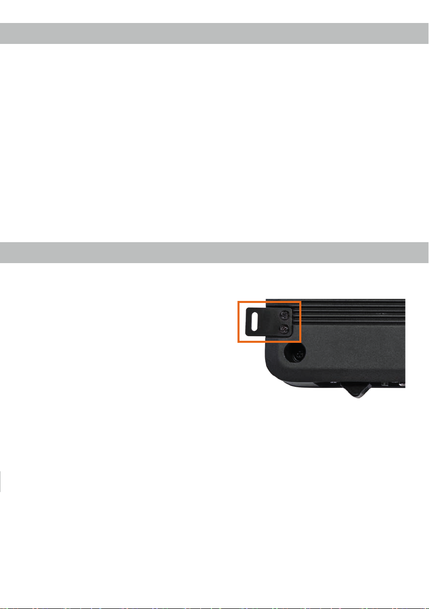
4. Im Sinne der Unfallsicherheit muss der
U 8A / U 10A professionell montiert werden.
Verwenden Sie hierzu die vier im Lieferum-
fang enthaltenen Befestigungslaschen. Diese
werden mit jeweils zwei kurzen Schrauben
(im Lieferumfang enthalten) an der Unterseite
des Aktiv-Subwoofers befestigt (siehe nachfol-
gendes Bild).
Wenn Sie den Aktiv-Subwoofer mittels Schrau-
ben an der Karosserie befestigen, so vergewis-
sern Sie sich, dass keine elektrischen Kabel
und Komponenten, hydraulische Bremslei-
tungen, der Benzintank etc. dahinter verborgen
sind. Diese könnten sonst beschädigt werden.
Achten Sie bitte darauf, dass sich solche Teile
auch in der doppelten Wandverkleidung verber-
gen können.
5. Installieren Sie den Aktiv-Subwoofer nicht an
Orten, an denen Wasser auf das Gehäuse
tropfen kann oder in der Nähe von wärmeab-
strahlenden Teilen sowie elektronischen Steue-
rungen des Fahrzeuges.
6. Die Qualität und Sorgfalt des Einbaus hat ent-
scheidenden Einuss auf den Klang des Aktiv-
Subwoofers. Bitte führen Sie jeden Schritt mit
größtmöglicher Sorgfalt durch.
Herzlichen Glückwunsch!
Allgemeine Hinweise

3
Allgemeine Hinweise zum Anschluss von HELIX
Aktiv-Subwoofern
Der Aktiv-Subwoofer darf nur in Kraftfahrzeuge ein-
gebaut werden, die den 12 V-Minuspol an Masse
haben. Bei anderen Systemen können der HELIX
U 8A / U 10A und die elektrische Anlage des Kfz
beschädigt werden. Die Plusleitung für die gesamte
Anlage sollte in einem Abstand von max. 30 cm von
der Batterie mit einer Hauptsicherung abgesichert
werden. Der Wert der Sicherung errechnet sich aus
der maximalen Stromaufnahme der Car-Hi Anlage.
Verwenden Sie zum Anschluss des Aktiv-Sub-
woofers an die Stromversorgung des Fahr-
zeugs ausschließlich geeignete Kabel mit aus-
reichendem Kabelquerschnitt. Die Sicherung
im Aktiv-Subwoofer darf nur mit dem gleichen
Wert (25 A) ersetzt werden, um eine Beschädi-
gung des Gerätes zu verhindern. Höhere Werte
können zu gefährlichen Folgeschäden führen!
Wir empfehlen Ihnen einen kurzen Funktionstest
bei geringer Lautstärke durchzuführen, um sicher-
zugehen, dass der Aktiv-Subwoofer vor seiner end-
gültigen Montage auch korrekt funktioniert.
Die Kabelverbindungen müssen so verlegt sein,
dass keine Klemm-, Quetsch- oder Bruchgefahr be-
steht. Bei scharfen Kanten (Blechdurchführungen)
müssen alle Kabel gegen Durchscheuern gepols-
tert sein. Ferner darf das Versorgungskabel niemals
mit Zuleitungen zu Vorrichtungen des Kfz (Lüfter-
motoren, Brandkontrollmodulen, Benzinleitungen
etc.) verlegt werden.
Wichtig: Achten Sie darauf, dass der Aktiv-Sub-
woofer phasenrichtig angeschlossen ist, d.h. Plus
zu Plus und Minus zu Minus.
4
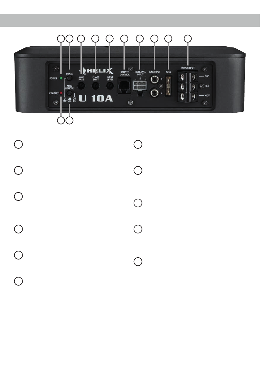
1Power & Protect LEDs
Die Power & Protect LEDs zeigen den
Betriebszustand des Aktiv-Subwoofers an.
2Phase
Schalter zur Umschaltung der Phase zwi-
schen 0° und 180°.
3Auto Remote
Dient zum Aktivieren bzw. Deaktivieren der
automatischen Einschaltung über die High-
level-Eingänge des Aktiv-Subwoofers.
4Lowpass
Regler zum Einstellen des Tiefpasslters von
50 Hz bis 150 Hz.
5Phase Shift
Regler zur stufenlosen Feinabstimmung der
Phase von 0° bis 180°.
6Input Level
Regler zum Einstellen der Eingangsempnd-
lichkeit des Line und Highlevel Inputs.
7Remote Control
Eingang zum Anschluss der mitgelieferten
Fernbedienung zur Lautstärkeregelung.
8Highlevel Input
Hochpegel-Lautsprechereingang zum An-
schluss von Werksradios oder Radios ohne
Vorverstärkerausgänge.
9Line Input
Cinch-Eingänge zum Anschluss eines Vor-
verstärkersignals.
10 Fuse
Eingangssicherung zum Schutz vor
geräteinternen Fehlern. Der Sicherungswert
beträgt 25 Ampere.
11 Power Input
Zum Anschluss an die Bordnetzspannung
und Eingang für die Remoteleitung.
Anschluss- und Bedienelemente
1 2 6 8 9 104 5 7
1 3
11

5
1Power & Protect LEDs
Die Power und Protect LEDs zeigen den Be-
triebszustand des Aktiv-Subwoofers an. Leuchtet
die Power LED grün, ist der Aktiv-Subwoofer einge-
schaltet und betriebsbereit.
Leuchtet die Protect LED rot, besteht eine Fehl-
funktion des Aktiv-Subwoofers. Diese Fehlfunkti-
on kann unterschiedliche Ursachen haben, da der
U 8A / U 10A mit verschiedenen elektronischen
Schutzschaltungen ausgestattet ist. Diese schal-
ten den Aktiv-Subwoofer bei Überhitzung, Über-
und Unterspannung und Fehlanschluss ab. Prüfen
Sie in diesem Fall alle Anschlüsse auf Fehler, wie
z.B. Kurzschlüsse, fehlerhafte Verbindungen oder
Falscheinstellungen und Übertemperatur. Sollte
sich der Aktiv-Subwoofer nach Beseitigung der
Fehlerquelle nicht wieder einschalten lassen, liegt
ein Defekt vor.
2Phase
Mit Hilfe dieses Schalters kann die Phasenlage
zwischen 0° und 180° umgeschaltet werden. Dies
ermöglicht eine bessere Ankopplung des Aktiv-
Subwoofers an die Tieftonwiedergabe der rest-
lichen Lautsprechersysteme und verhindert ein
Auslöschen der tiefen Frequenzen aufgrund falsch-
er Phasenlage. Sollte die Umschaltung nicht zum
gewünschten Ergebnis führen, kann mit Hilfe des
Reglers 5 (Phase Shift) eine Feinabstimmung vor-
genommen werden.
3Auto Remote
Die Einschaltung des Aktiv-Subwoofers erfolgt
automatisch bei Ansteuerung über die Hochpe-
gel-Lautsprechereingänge (Highlevel Input) oder
sobald ein Remote-Signal am Remote-Eingang
(REM) des Power Inputs anliegt.
Mit Hilfe des Auto Remote Schalters kann die au-
tomatische Einschaltung über die Hochpegel-Laut-
sprechereingänge aktiviert bzw. deaktiviert werden.
Die Deaktivierung (Auto Remote = Off) sollte vorge-
nommen werden, wenn es beispielsweise zu Stör-
geräuschen beim Ein- und Ausschalten des Aktiv-
Subwoofers kommt.
Hinweis: Wird die automatische Einschaltung des
Aktiv-Subwoofers deaktiviert, muss der Remote-
Eingang belegt werden. Eine automatische Ein-
schaltung über den Hochpegel-Lautsprecherein-
gang ist dann nicht mehr möglich.
4Lowpass
Mit Hilfe dieses Reglers kann das Tiefpasslter von
50 Hz bis 150 Hz eingestellt werden. Als sinnvollen
Startwert zur Anpassung des Aktiv-Subwoofers an
die restlichen Lautsprechersysteme empfehlen wir
eine Einstellung von 100 Hz (Mittelstellung des
Reglers).
5Phase Shift
Mit Hilfe dieses Reglers kann eine Feineinstellung
der Phase von 0° bis 180° vorgenommen werden,
sofern die Phasenanpassung mit Hilfe des Phasen-
Schalters (siehe Punkt 2) nicht zum gewünschten
Ergebnis geführt hat.
Hinweis: Verwenden Sie bitte immer zuerst den
Phase-Schalter zur Anpassung der Phasenlage.
6Input Level
Mit Hilfe dieses Reglers kann die Eingangsempnd-
lichkeit an die Ausgangsspannung des angeschlos-
senen Radios angepasst werden.
Der Regelbereich des Cinch-Eingangs (Line Input)
liegt zwischen 0,3 - 4 Volt und 1,2 - 20 V für den
Hochpegeleingang (Highlevel Input).
7Remote Control
Eingang zum Anschluss der im Lieferumfang ent-
haltenen Kabelfernbedienung. Mit Hilfe dieser
Fernbedienung lässt sich die Lautstärke des Aktiv-
Subwoofers kontrollieren.
Inbetriebnahme und Funktionen

6
Inbetriebnahme und Funktionen
8Highlevel Input
2-Kanal Hochpegel-Lautsprechereingang. Mit Hilfe
dieses Eingangs kann der Aktiv-Subwoofer direkt
an die Lautsprecherausgänge eines Werks- / Nach-
rüstradios angeschlossen werden, sofern dieses
nicht über Vorverstärkerausgänge verfügt.
Bei Verwendung dieses Eingangs schaltet der
Aktiv-Subwoofer bei allen handelsüblichen Radios
automatisch ein, so dass dieser nicht über den Re-
mote-Eingang (REM) des Power Input eingeschal-
tet werden muss.
Achtung: Verwenden Sie zum Anschluss aus-
schließlich das mitgelieferte Anschlusskabel mit
dem 6-poligen Stecker und den offenen Kabel-
enden.
Achtung: Eine gleichzeitige Verwendung der
Hochpegel- und Vorverstärkersignaleingänge ist
nicht möglich und kann zu Schäden an Ihrem Au-
toradio führen.
9Line Input
2-Kanal Vorverstärkereingang zum Anschluss von
Signalquellen, wie z.B. Radios, die mit dem / den
Vorverstärkerausgang/-ausgängen bzw. Line Out-
puts der Signalquelle verbunden werden können.
Achtung: Eine gleichzeitige Verwendung der
Hochpegel- und Vorverstärkersignaleingänge ist
nicht möglich und kann zu Schäden an Ihrem Au-
toradio führen.
10 Fuse
Die Eingangssicherung ist parallel geschaltet und
schützt vor einem geräteinternen Fehler, d.h. die
Anlage muss mit einer zusätzlichen Sicherung in
Nähe der Batterie (max. 30 cm entfernt) abgesi-
chert werden. Der Sicherungswert für den Aktiv-
Subwoofer beträgt 25 Ampere.
11 Power Input
Diese Kontakte dienen zum Anschluss der Span-
nungsversorung und der Remote-Leitung.
+12 V: Das +12 V Versorgungskabel ist am Pluspol
der Batterie anzuschließen. Die Plusleitung
sollte in einem Abstand von max. 30 cm
von der Batterie mit einer Hauptsicherung
abgesichert werden. Der Wert der Siche-
rung errechnet sich aus der maximalen
Stromaufnahme der gesamten Car-Hi An-
lage. Verwenden Sie bei kurzen Leitungen
(< 1 m) einen Querschnitt von mindestens
4 mm². Bei längeren Leitungen empfehlen
wir einen Querschnitt von 6 mm².
GND: Das Massekabel (gleicher Querschnitt
wie das +12 V Kabel) sollte am zentralen
Massepunkt (dieser bendet sich dort wo
der Minuspol der Batterie zum Metallchassis
des Kfz geerdet ist) oder an einer blanken,
von Lackresten befreiten Stelle des Kfz-
Chassis angeschlossen werden.
REM: Die Remoteleitung wird mit dem Remote-
Ausgang /Antennenanschluss des Steuer-
gerätes (Radio) verbunden. Dieser ist nur
aktiviert, wenn das Steuergerät eingeschal-
tet ist. Somit wird der Aktiv-Subwoofer mit
dem Steuergerät ein- und ausgeschaltet.
Dieser Eingang muss nicht belegt werden,
wenn der Hochpegel-Lautsprechereingang
(Highlevel Input) benutzt wird.
7
Einbau und Installation
L
R
Links
Rechts
Kabelfernbe-
dienung
Sicherung
Max. Abstand zur
Spannungsquelle:
30 cm
Spannungsquelle
Masse
Remote-Leitung
Masse
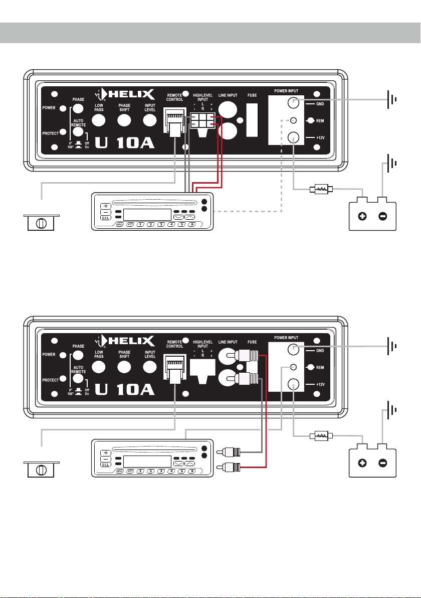
Option 2: Anschluss des Aktiv-Subwoofers bei Verwendung der Cinch-Eingänge
Hinweis: Bei Verwendung der Cinch-Eingänge als Signaleingang muss der Remote-Eingang zwingend belegt werden.
L +
Kabelfernbe-
dienung
Sicherung
Max. Abstand zur
Spannungsquelle:
30 cm
Spannungsquelle
Masse
optional: Remote-Leitung
Masse
R +L - R -
Option 1: Anschluss des Aktiv-Subwoofers bei Verwendung der Highlevel-Eingänge
Hinweis: Bei Verwendung der Highlevel-Eingänge als Signaleingang schaltet der Aktiv-Subwoofer automatisch ein, so
dass der Remote-Eingang nicht belegt werden muss. Stellen Sie dazu den Auto Remote-Schalter auf „On“. Sollte es zu
Störgeräuschen beim Ein- und Ausschalten kommen, verwenden Sie bitte den Remote-Eingang und stellen den Auto
Remote-Schalter auf „Off“.

8
Der HELIX U 8A / U 10A wird wie nachfolgend
beschrieben an das Autoradio angeschlossen.
Achtung: Für die Durchführung der nachfolgenden
Schritte werden Spezialwerkzeuge und Fachwissen
benötigt. Um Anschlussfehler und Beschädigungen
zu vermeiden, fragen Sie im Zweifelsfall Ihren Ein-
bauspezialisten und beachten Sie zwingend die
allgemeinen Anschluss- und Einbauhinweise (siehe
Seite 2).
1. Anschluss der Highlevel-Lautsprecherein-
gänge
Die Hochpegel-Lautsprechereingänge L und R
(Highlevel Input) können direkt mit den Laut-
sprecherausgängen des Werks- bzw. Nachrüst-
radios mit Hilfe entsprechender Kabel (Laut-
sprecherkabel mit max. 1 mm² Querschnitt)
verbunden werden. Dabei müssen nicht zwin-
gend beide Eingänge belegt werden. Wir emp-
fehlen jedoch folgende Kanalbelegung:
Kanal L = Links vorne
Kanal R = Rechts vorne
Achten Sie bitte auf eine korrekte Polung! Wenn
Sie einen Anschluss verpolen, kann dadurch
die Funktion des Aktiv-Subwoofers beeinträch-
tigt werden und ggf. die Tonwiedergabe voll-
ständig unterbunden werden. Bei Verwendung
dieses Eingangs muss der Remote-Eingang
(REM) nicht belegt werden, da sich der Aktiv-
Subwoofer automatisch einschaltet, sobald ein
Lautsprechersignal anliegt.
Achtung: Eine gleichzeitige Verwendung der
Hochpegel- und Vorverstärkersignaleingänge
ist nicht möglich und kann zu Schäden an Ihrem
Autoradio führen.
2. Anschluss der Vorverstärkereingänge
Diese Eingänge (Line Input) können mit ent-
sprechenden Kabeln (RCA / Cinch-Kabel) an
die Vorverstärker- / Lowlevel- / Cinch-Ausgän-
ge des Radios angeschlossen werden. Dabei
müssen nicht zwingend beide Eingänge belegt
werden. Wir empfehlen jedoch eine Belegung
beider Kanäle. Die Einschaltautomatik des
Aktiv-Subwoofers funktioniert bei den Vorver-
stärkereingängen nicht, so dass der Remote-
Eingang (REM) zwingend belegt werden muss.
3. Einstellung der Eingangsempndlichkeit
Achtung: Es ist zwingend notwendig die
Eingangsempndlichkeit des U 8A / U 10A
an die Signalquelle anzupassen, um Schä-
den am Aktiv-Subwoofer zu vermeiden.
Um die Eingangsempndlichkeit zu verändern,
verwenden Sie den Input Level-Drehregler
(siehe Seite 5, Punkt 6). Die Einstellung dieses
Reglers beeinusst sowohl die Vorverstärker-
eingänge (Line Input) als auch die Hochpegel-
Lautsprechereingänge (Highlevel Input)!
4. Anschluss der Stromversorgung
Vor dem Anschluss des +12 V Versorgungs-
kabels an das Bordnetz muss die Autobatte-
rie abgeklemmt werden.
Das +12 V Stromkabel ist am Pluspol der Bat-
terie anzuschließen. Die Plusleitung sollte in
einem Abstand von max. 30 cm von der Batte-
rie mit einer Hauptsicherung abgesichert wer-
den. Der Wert der Sicherung errechnet sich aus
der maximalen Stromaufnahme der gesamten
Car-Hi Anlage (U 8A / U 10A = max. 25 A RMS
bei 12 V Bordnetz). Verwenden Sie bei kurzen
Leitungen (< 1 m) einen Querschnitt von minde-
stens 4 mm². Bei längeren Leitungen empfeh-
len wir einen Querschnitt von 6 mm². Das Mas-
sekabel (gleicher Querschnitt wie das +12 V
Kabel) muss an einem blanken, von Lackresten
befreiten Massepunkt des Kfz-Chassis oder
direkt an dem Minuspol der Autobatterie ange-
schlossen werden.
5. Anschluss des Remote-Eingangs
Der Remote-Eingang (REM) muss mit dem
Remote-Ausgang des Radios verbunden sein,
sofern die Vorverstärkereingänge des Aktiv-
Subwoofers als Signaleingänge genutzt wer-
den. Es wird dringend davon abgeraten, den
Remote-Eingang des Aktiv-Subwoofers über
das Zündungsplus des Fahrzeugs zu steuern,
um Störgeräusche beim Ein- und Ausschalten
zu vermeiden. Bei Verwendung des Highlevel-
Eingangs (Highlevel Input) muss der Remote-
Eingang nicht belegt werden, sofern das ange-
schlossene Radio über BTL-Ausgangsstufen
verfügt und der Auto Remote-Schalter auf „On“
steht.
Einbau und Installation

9
6. Konguration des Remote-Eingangs
Die Einschaltung des U 8A / U 10A erfolgt
automatisch bei Ansteuerung über die Hoch-
pegel-Lautsprechereingänge oder sobald ein
Remote-Signal am Remote-Eingang (REM)
anliegt. Mit Hilfe des Auto Remote Schalters
(Seite 5, Punkt 3; Auto Remote) kann die au-
tomatische Einschaltung über die Hochpegel-
Lautsprechereingänge deaktiviert werden. Dies
sollte vorgenommen werden, wenn es bei-
spielsweise zu Störgeräuschen beim Ein- und
Ausschalten des Aktiv-Subwoofers kommt.
Hinweis: Wird die automatische Einschaltung
des U 8A / U 10A deaktiviert, muss der Remo-
te-Eingang belegt werden. Eine automatische
Einschaltung über den Hochpegel-Lautspre-
chereingang ist dann nicht mehr möglich. Um
die automatische Einschaltung zu deaktivieren,
stellen Sie den Auto Remote-Schalter auf die
Schalterstellung „Off“.

10
Technische Daten
Die Garantieleistung entspricht der gesetzlichen
Regelung. Von der Garantieleistung ausgeschlos-
sen sind Defekte und Schäden, die durch Überla-
stung oder unsachgemäße Behandlung entstanden
sind. Eine Rücksendung kann nur nach vorheriger
Absprache in der Originalverpackung, einer de-
taillierten Fehlerbeschreibung und einem gültigen
Kaufbeleg erfolgen.
Technische Änderungen und Irrtümer vorbehalten!
Für Schäden am Fahrzeug oder Gerätedefekte, her-
vorgerufen durch Bedienungsfehler des Gerätes,
können wir keine Haftung übernehmen. Dieses
Produkt ist mit einer CE-Kennzeichnung versehen.
Damit ist das Gerät für den Betrieb in Fahrzeugen
innerhalb der Europäischen Union (EU) zertiziert.
Garantiehinweis
U 8A U 10A
Leistung RMS / Max. 180 / 360 Watt 180 / 360 Watt
Durchmesser Tieftöner 200 mm 250 mm
Eingänge 2 x Cinch
2 x Hochpegel-Lautsprecherein-
gang
1 x Remote In
1 x Fernbedienungseingang
2 x Cinch
2 x Hochpegel-Lautsprecherein-
gang
1 x Remote In
1 x Fernbedienungseingang
Eingangsempndlichkeit Hochpegel 1,2 - 20 Volt
Cinch 0,3 - 4 Volt
Hochpegel 1,2 - 20 Volt
Cinch 0,3 - 4 Volt
Eingangsimpedanz Cinch 10 kOhm 10 kOhm
Eingangsimpedanz Highlevel 33 Ohm 33 Ohm
Frequenzbereich
45 - 150 Hz 40 - 150 Hz
Tiefpass 50 - 150 Hz regelbar 50 - 150 Hz regelbar
Subsonic 16 Hz / 12 dB/Okt. 16 Hz / 12 dB/Okt.
Phasenschalter 0° / 180° umschaltbar 0° / 180° umschaltbar
Phasenregler 0 - 180° regelbar 0 - 180° regelbar
Flankensteilheit Tiefpass 24 dB/Okt. 24 dB/Okt.
Signal- / Rauschabstand > 92 dB (A-bewertet) > 92 dB (A-bewertet)
Klirrfaktor (THD) < 0,4 % < 0,4 %
Betriebsspannung 10,5 - 16 Volt 10,5 - 16 Volt
Sicherung 25 A Maxi-Stecksicherung 25 A Maxi-Stecksicherung
Zusätzliche Features Gehäuse aus Aluminium-
Druckguss, Kabelfernbedienung
zur Lautstärkeregelung, Auto
Remote-Schalter
Gehäuse aus Aluminium-
Druckguss, Kabelfernbedienung
zur Lautstärkeregelung, Auto
Remote-Schalter
Abmessungen (H x B x T) 78 x 245 x 345 mm 78 x 245 x 345 mm
11
Dear Customer,
Congratulations on your purchase of this innovative
and high-quality HELIX product.
The active subwoofer was developed according to
the latest technical ndings and is characterized by
excellent workmanship and convincing sound.
Thanks to more than 30 years of experience in
research and development of audio products this
active subwoofer generation sets new standards.
We wish you many hours of enjoyment with your
new HELIX active subwoofer.
Yours,
AUDIOTEC FISCHER Team
General installation instructions for HELIX
components
To prevent damage to the unit and possible injury,
read this manual carefully and follow all installation
instructions. This product has been checked for
proper function prior to shipping and is guaranteed
against manufacturing defects.
Before starting your installation, disconnect the
battery’s negative terminal to prevent damage
to the unit, re and / or risk of injury. For a proper
performance and to ensure full warranty coverage,
we strongly recommend to get this product installed
by an authorized HELIX dealer.
1. Check that the space between the active sub-
woofer and other parts, such as the car seat
etc., is sufcient.
2. Take care that the mounting surface is at and
free from all obstructions.
3. Ensure that the active subwoofer is correctly
connected (phase), i.e. plus to plus and minus
to minus.
4. For safety reasons, the U 8A / U 10A must be
professionally installed. Therefore, use the four
mounting brackets which are included in de-
livery. These are attached to the bottom of the
active subwoofer with two short screws which
are included in delivery, too (see following pic-
ture).
When screwing the active subwoofer to the ve-
hicle chassis, carefully examine the area
around and behind the proposed installation lo-
cation to ensure that there are no electrical ca-
bles or components, hydraulic brake lines or
any part of the fuel tank located behind the
mounting surface. Failure to do so may result in
unpredictable damage to these components
and possible costly repairs to the vehicle.
5. Do not mount the active subwoofer where water
may splash on it or close to heat-radiating parts
and electronic controls of the vehicle.
6. The quality of the installation has a signicant
effect on the overall performance of the active
subwoofer. Treat each installation step with a
high degree of attention.
Congratulations!
General instructions

12
General instructions for connecting HELIX
active subwoofers
The active subwoofer may only be installed in vehi-
cles which have a 12 Volts negative terminal con-
nected to the chassis ground. Any other system
could cause damage to the HELIX U 8A / U 10A and
the electrical system of the vehicle.
The positive cable from the battery for the complete
system should be provided with a main fuse at a
distance of max. 30 cm from the battery. The val-
ue of the fuse is calculated from the maximum total
current input of the car audio system.
Use only suitable cables with sufcient cable
cross-section for the connection of the active
subwoofer. The fuse may only be replaced by
an identically rated fuse (25 A) to avoid damage
of the active subwoofer. Higher values can lead
to dangerous consequential damage!
We recommend that you perform a short function
test at low volume to ensure that the active sub-
woofer is functioning correctly before nal installa-
tion.
Prior to installation, plan the wire routing to avoid
any possible damage to the wire harness. All
cabling should be protected against possible crush-
ing or pinching hazards. Also avoid routing cables
close to potential noise sources such as electric
motors, high power accessories and other vehicle
harnesses.
Attention: Ensure that the active subwoofer is cor-
rectly connected (phase), i.e. plus to plus and minus
to minus.
General instructions

13
Connectors and control units
1Power & Protect LEDs
These LEDs indicate the operating mode of
the active subwoofer.
2Phase
This switch allows to switch the phase
between 0° and 180°.
3Auto Remote
This switch allows to activate / deactivate the
automatic turn-on feature via the highlevel
inputs of the active subwoofer.
4Lowpass
Control for adjusting the lowpass lter from
50 Hz to 150 Hz.
5Phase Shift
Control for continuous ne tuning of the
phase from 0° to 180°.
6Input Level
Control for adjusting the input sensitivity of
the lowlevel Line and Highlevel Inputs.
7Remote Control
Input for connecting the included cable
remote control for volume adjustment.
8Highlevel Input
Highlevel speaker inputs for connecting a
factory radio or an aftermarket radio without
lowlevel line outputs.
9Line Input
RCA inputs for connecting lowlevel line
signals.
10 Fuse
Input fuse - 1 x 25 Ampere.
11 Power Input
Connector for the power supply and the
remote cable.
1 2 6 8 9 104 5 7
1 3
11

14
Initial start-up and functions
1Power & Protect LEDs
The Power & Protect LEDs indicate the operating
mode of the active subwoofer. If the Power LED
lights green, the active subwoofer is switched on
and ready for operation.
If the Protect LED lights up red a malfunction has
occurred. A malfunction may have different causes
as the HELIX U 8A / U 10A is equipped with different
protection circuits. These protections shut off the
active subwoofer in case of overheating, over- and
undervoltage and false connection. Please check
for connecting failures such as short-circuits, wrong
connections, wrong adjustments and over temper-
ature. If the active subwoofer does not turn on it is
defective and has to be send to your local author-
ized dealer for repair service. A detailed description
of the malfunction and the purchase receipt has to
be attached.
2Phase
This switch is used to toggle the phase between 0°
and 180°. This allows to match the phase of the ac-
tive subwoofer with the other speakers thus avoid-
ing any cancellations in the frequency response due
to phase shifts. If the changeover does not lead to
the desired result, a ne tuning can be done with
control 5 (Phase Shift).
3Auto Remote
The U 8A / U 10A will be turned on automatically if
the Highlevel Input is used or if a signal is applied to
the remote input (REM) terminal of the Power Input.
The Auto Remote switch allows to activate / deacti-
vate the automatic turn-on feature of the Highlevel
Input. The feature should be deactivated (Auto Re-
mote = Off) if there are e.g. disturbing noises while
switching on /off the active subwoofer.
Note: If the automatic turn-on function is deactivat-
ed it is mandatory to use the remote input to power
up the active subwoofer! The highlevel signal will be
ignored in this case.
4Lowpass
This control is used to adjust the crossover frequen-
cy of the lowpass lter from 50 Hz to 150 Hz. As
a reasonable initial value for adapting the active
subwoofer to the other loudspeaker systems, we
recommend a setting of 100 Hz (center position of
the control).
5Phase Shift
This control is used to ne tune the phase from 0° to
180° if the phase adjustment with the Phase switch
(see item 2) did not lead to the desired result.
Note: Always use the Phase switch rst to adjust
the phase.
6Input Level
This control is used to adapt the input sensitivity to
the output voltage of the connected signal source.
The control range of the RCA / Line Input (lowlevel)
is 0.3 - 4 Volts and 1.2 - 20 Volts for the Highlevel
Input.
7Remote Control
This input is used to connect the included cable re-
mote control. The remote control allows you to con-
trol the volume of the active subwoofer.
8Highlevel Input
2-channel highlevel loudspeaker input to connect
the active subwoofer directly to the loudspeaker
outputs of OEM / aftermarket radios that do not
have any lowlevel line outputs.
If this input is used the remote input (REM) of the
Power Input does not need to be connected as the
active subwoofer will automatically turn on once a
loudspeaker signal is applied.
Attention: Solely use the connection cable with the
6-pole connector and ying leads which is included
in delivery!

15
Important: It is strictly forbidden to use the High-
level Input and lowlevel Line Input at the same time.
This may cause severe damage to the lowlevel line
outputs of your car radio.
9Line Input
2-channel lowlevel line input to connect signal
sources such as head units / radios / DSPs.
Important: It is strictly forbidden to use the High-
level Input and lowlevel Line Input at the same time.
This may cause severe damage to the lowlevel line
outputs of your head unit / car radio.
10 Fuse
The input fuse is connected in parallel and provide
protection against an internal fault of the device,
therefore the system must be additionally protect-
ed by a further main fuse located close to the bat-
tery (max. distance from battery: 30 cm / 12”). The
HELIX U 8A / U 10A is equipped with a 25 Ampere
fuse.
11 Power Input
This input is used for connecting the active sub-
woofer to the power supply of the vehicle and for
the remote input.
+12 V: The +12 V supply cable must be connected
to the positive terminal of the battery. The
positive wire from the battery to the pow-
er terminal of the active subwoofer needs
to have an inline fuse at a distance of less
than 12 inches (30 cm) from the battery.
The value of the fuse is calculated from the
maximum total current draw of the whole
car audio system. If your power wires are
short (less than 1 m / 40”) then a wire gauge
of 4 mm² / AWG 12 will be sufcient. In all
other cases we recommend a cross section
6 mm² / AWG 10!
GND: The ground cable (same gauge as the
+12 V wire) should be connected to a com-
mon ground reference point (this is located
where the negative terminal of the battery is
grounded to the metal body of the vehicle),
or to a prepared metal location on the ve-
hicle chassis, i.e. an area which has been
cleaned of all paint residues.
REM: The remote lead should be connected to the
remote output / automatic antenna (aerial
positive) output of the head unit / car ra-
dio. This is only activated if the head unit is
switched on. Thus the active subwoofer is
switched on and off together with the head
unit / car radio. This input needn’t to be as-
signed if the Highlevel Input is used.

16
Installation
Left
Right
Left
Right
Cable remote
control
Fuse
Max. distance to the
power source:
30 cm
Power source
Ground
Remote cable
Ground
Option 2: Connecting the active subwoofer when using the RCA / Cinch inputs
Note: If the RCA / Cinch inputs are used as signal inputs, the remote input has to be used.
L +
Cable remote
control
Fuse
Max. distance to the
power source:
30 cm
Power source
Ground
optional: Remote cable
Ground
R +L - R -
Option 1: Connecting the active subwoofer when using the highlevel inputs
Note: If the highlevel inputs are used as signal inputs, the remote input does not need to be connected as the active
subwoofer will automatically turn on once a loudspeaker signal is applied. To do this, set the Auto Remote switch to “On”
position. If there are any disturbing noises while switching on and off the active subwoofer, please use the remote input
and set the Auto Remote switch to “Off” position.

17
Connection of HELIX U 8A / U 10A to the head
unit / car radio:
Caution: Carrying out the following steps will re-
quire special tools and technical knowledge. In or-
der to avoid connection mistakes and / or damage,
ask your dealer for assistance if you have any ques-
tions and follow all instructions in this manual (see
page 11 et sqq.). It is recommended that this unit
will be installed by an authorized HELIX dealer.
1. Connecting the highlevel speaker inputs
The highlevel loudspeaker inputs L and R can
be connected directly to the loudspeaker out-
puts of an OEM or aftermarket radio using
appropriate cables (loudspeaker cables with
1 mm² / AWG 18 max.).
Actually it is not mandatory to use both highlev-
el speaker inputs. However, we recommend the
following channel assignment:
Channel L = Front left
Channel R = Front right
Make sure that the polarity is correct. If one
connection has reversed polarity it may affect
the performance of the active subwoofer and
the sound reproduction may be completely sup-
pressed.
When using this input, the remote input (REM)
does not need to be connected as the active
subwoofer will automatically turn on once a
loudspeaker signal is applied.
Important: It is strictly forbidden to use the
Highlevel Input and lowlevel Line Input at the
same time. This may cause severe damage to
the lowlevel line outputs of your car radio.
2. Connecting the lowlevel line inputs
Use the correct cable (RCA / Cinch cable) to
connect these inputs to the lowlevel line outputs
of your car radio. It is not mandatory to use both
lowlevel line inputs. However, we recommend
to use both inputs.
The automatic turn-on circuit does not work
when using the lowlevel line inputs. In this case
the remote input (REM) has to be connected to
activate the HELIX U 8A / U 10A.
3. Adjustment of the input sensitivity
Attention: It is mandatory to properly adapt
the input sensitivity of the U 8A / U 10A to
the signal source in order to avoid damage
to the active subwoofer.
If you want to change the input sensitivity use
the Input Level control (see page 14, item 6).
The setting of the control affects both the low-
level line inputs (Line Input) and the highlevel
speaker inputs (Highlevel Input)!
4. Connection to power supply
Make sure to disconnect the battery before
installing the HELIX U 8A / U 10A!
Connect the +12 V power cable to the positive
terminal of the battery. The positive wire from
the battery to the power terminal of the active
subwoofer needs to have an inline fuse at a dis-
tance of less than 12 inches (30 cm) from the
battery.
The value of the fuse is calculated from the
maximum total current draw of the whole car
audio system (U 8A / U 10A = max. 25 A RMS
at 12 V power supply). If your power wires are
short (less than 1 m / 40”) then a wire gauge of
4 mm² / AWG 12 will be sufcient. In all other
cases we recommend a gauge of 6 mm²/ AWG
10!
The ground cable (same gauge as the +12 V
wire) should be connected to a common ground
reference point (this is located where the neg-
ative terminal of the battery is grounded to the
metal body of the vehicle), or to a prepared met-
al location on the vehicle chassis, i.e. an area
which has been cleaned of all paint residues.
5. Connecting the remote input
The remote input (REM) has to be connected to
the radio remote output if the active subwoofers
lowlevel line inputs are used as signal inputs.
We do not recommend controlling the remote
input via the ignition switch to avoid pop noise
during turn on/off.
If the Highlevel Input is used this input does not
need to be connected as long as the car radio
has BTL output stages.

18
6. Conguration of the remote input
The U 8A / U 10A will be turned on automatical-
ly if the highlevel inputs are used or if a signal is
applied to the remote input terminal. The Auto
Remote switch (see page 14, item 3; Auto Re-
mote) allows to deactivate the automatic turn-
on feature of the highlevel inputs. The feature
should be deactivated if there are e.g. disturb-
ing noises while switching on / off the active
subwoofer.
Note: If the automatic turn-on function is deac-
tivated it is mandatory to use the remote input
terminal to power up the active subwoofer! The
highlevel signal will be ignored in this case. To
deactivate the automatic turn-on feature you
have to change the position of the Auto Remote
switch to “Off”.
Installation

19
The limited warranty comply with legal regulations.
Failures or damages caused by overload or im-
proper use are not covered by the warranty. Please
return the defective product only with a valid proof
of purchase and a detailed malfunction description.
Technical specications are subject to change!
Errors are reserved! For damages on the vehicle
and the device, caused by handling errors of the
device, we can’t assume liability. These devices are
certied for the use in vehicles within the European
Community (EC).
Technical Data
Warranty Disclaimer
U 8A U 10A
Power RMS / max. 180 / 360 Watts 180 / 360 Watts
Woofer diameter 8” / 200 mm 10” / 250 mm
Inputs 2 x RCA / Cinch
2 x Highlevel speaker input
1 x Remote In
1 x Remote control input
2 x RCA / Cinch
2 x Highlevel speaker input
1 x Remote In
1 x Remote control input
Input sensitivity Highlevel 1.2 - 20 Volts
RCA / Cinch 0.3 - 4 Volts
Highlevel 1.2 - 20 Volts
RCA / Cinch 0.3 - 4 Volts
Input impedance RCA / Cinch 10 kOhms 10 kOhms
Input impedance highlevel 33 Ohms 33 Ohms
Frequency response
45 - 150 Hz 40 - 150 Hz
Lowpass 50 - 150 Hz adjustable 50 - 150 Hz adjustable
Subsonic 16 Hz / 12 dB/Oct. 16 Hz / 12 dB/Oct.
Phase switch 0° / 180° switchable 0° / 180° switchable
Phase shift 0 - 180° adjustable 0 - 180° adjustable
Slope lowpass 24 dB/Oct. 24 dB/Oct.
Signal-to-noise ratio > 92 dB (A-weighted) > 92 dB (A-weighted)
Distortion (THD) < 0.4 % < 0.4 %
Operating voltage 10.5 - 16 Volts 10.5 - 16 Volts
Fuse 25 A Maxi-fuse (APX) 25 A Maxi-fuse (APX)
Additional features Diecast aluminum housing, cable
remote control for volume adjust-
ment, Auto Remote switch
Diecast aluminum housing, cable
remote control for volume adjust-
ment, Auto Remote switch
Dimensions (H x W x D) 78 x 245 x 345 mm /
3.07 x 9.65 x 13.58”
78 x 245 x 345 mm /
3.07 x 9.65 x 13.58”

Audiotec Fischer GmbH
Hünegräben 26 · 57392 Schmallenberg · Germany
Tel.: +49 2972 9788 0 · Fax: +49 2972 9788 88
E-mail: helix@audiotec-scher.com · Internet: www.audiotec-scher.com
This manual suits for next models
1
Table of contents
Languages:
Other HELIX Subwoofer manuals

HELIX
HELIX DEEP BLUE 12 User manual

HELIX
HELIX Blue B 8DSP User manual

HELIX
HELIX P12 Precision User manual

HELIX
HELIX DEEP BLUE 10 User manual

HELIX
HELIX DB 8A User manual

HELIX
HELIX P10 Precision User manual

HELIX
HELIX COMPOSE i7 User manual

HELIX
HELIX SPXL 12 User manual

HELIX
HELIX P8 Precision User manual


