Hella Induperm CCR 961-SW4.00 User manual

Regulator type CCR 961-SW4.00
USER MANUAL
GB

CCR961 MANUAL-GB
2
Version B2:01-07-2015
LIST OF CONTENT
1.General information......................................................................................................3
1.1The layout of this manual .........................................................................................................3
1.2The use of the manual ...............................................................................................................3
1.3Manufacturer information.........................................................................................................3
1.4Document information ..............................................................................................................3
2.Overall CCR 961 information......................................................................................4
2.1Relevant standards ....................................................................................................................4
2.2Main data...................................................................................................................................4
2.3CCR 961 variants......................................................................................................................5
2.4Warranty limitations .................................................................................................................6
3.CCR DESCRIPTION....................................................................................................6
3.1General Information..................................................................................................................6
3.2CCR Module (Standard) ...........................................................................................................8
3.3Operating Description.............................................................................................................14
3.4The menu’s..............................................................................................................................16
3.5Power Transformer .................................................................................................................17
4.CCR installation ..........................................................................................................18
4.1Unpacking the CCR shipment.................................................................................................18
4.2Before the installation .............................................................................................................18
4.3CCR installation......................................................................................................................18
5.Commissioning.............................................................................................................21
5.1Preparation ..............................................................................................................................21
5.2Control of settings in each menu.............................................................................................22
5.3Step by Step adjustments ........................................................................................................24
6.Remote Control............................................................................................................37
6.1Standard RS485 ......................................................................................................................37
6.2Redundant Profibus.................................................................................................................40
6.3Parallel control ........................................................................................................................45
6.4Ethernet IP addressable...........................................................................................................47
6.5Dip-switch settings..................................................................................................................48
7.Cut-Out devices............................................................................................................49
7.1Standard FAA connector type.................................................................................................49
7.2Key operated safety type.........................................................................................................50
8.Maintenance and Trouble shooting ...........................................................................51
8.1Regularly Control....................................................................................................................51
8.2Safety instructions...................................................................................................................51
8.3List of possible failures...........................................................................................................52

CCR961 MANUAL-GB
3
Version B2:01-07-2015
1. General information
1.1 The layout of this manual
This manual includes technical information about the Hella Induperm range of Constant Current
Regulators, CCR 961 with improved firmware, SW4.0xx.
The range of CCR’s are constructed and manufactured of standard parts, mostly produced in-house. As
the possible settings in the CCR’s are numerous, it is advised to study the manual carefully before any
settings are changed.
All standards settings and operations are detailed described in the Step-by-Step instruction in section
5.5.
1.2 The use of the manual
The manual is intended to be used for installation, operation, maintenance of the CCR, as well as for
purchase of spare parts.
1.3 Manufacturer information
The CCR 961 are developed and manufactured by:
HELLA INDUPERM A/S
Københavnsvej 1
DK-4800 Nykøbing Falster
DENMARK
Tel.: +45 5486 0200
Fax.: +45 5486 0389
E-mail: induperm@induperm.dk
Homepage: www.induperm.dk or www.hella.com/airportlighting
1.4 Document information
Version Date Author Approved
A –First release 2015.3.28 Ole Lund-Hermansen OLH
Version Date Author Approved Comments
B 2015.5.12 OLH OLH SW Version 4.00c included
B1 2015.5.26 OLH OLH Optional remote terminals added
B2 2015.9.10 OLH OLH New drwg. for Remote control terminals
This manual includes a number of safety instructions, but national instructions as well as
IEC 61820, Annex C, must be observed.
Hella Induperm A/S reserves the right to changes without notice.
It is not allowed to copy this manual without permission.

CCR961 MANUAL-GB
4
Version B2:01-07-2015
2Overall CCR 961 information
2.1 Relevant standards
The range CCR 961 is constructed, manufactured and tested to meet the latest EN IEC 61822 standard.
The performance of the CCR 961 has been verified in tests performed by TÜV SÜD in Germany.
The range of CCR961 meets the requirements in ICAO Annex 14, as well as ICAO Design Manual
2.2 Main data
The CCR 961 in FAA layout is a complete unit including CCR Thyristor module for 40A, 60A or
110A, built together with output transformer and all belonging hardware such as measuring
transformers, Isolation Measuring equipment and lightning protection devices.
Standard power ratings from 2,2 KVA to 35 KVA.
Standard 100% series circuit current can be selected in the SW between 2,2A / 6,6A and 13,2A
(However, measuring transformer must be changed as well), but we can supply 8,3A – 10A – and 20A
versions as well.
Standard input voltages are 230V / 400V (± 10%) - 50Hz or 60Hz (± 2 Hz)
Features
Seven individual adjustable intensity
steps.
Earth fault supervision with two alarm
levels.
Lamp supervision with two alarm levels.
Hour meters for 100% intensity and total
time.
All CCR adjustment stored on changeable
Memory board for easy and fast
maintenance
Digital display showing:
Output current (RMS value).
Output voltage (RMS value).
Input voltage.
Time/date through build-in watch.
Power output.
Impedance to earth.
Number of faulty lamps
Mechanical specifications:
Height (mm) Depth (mm) Width (mm) App. Weight
(KG)
CCR for 230V, Power rating 10 KVA 1666 600 390 175 – 240
CCR for 400V, Power rating 20 KVA 1666 600 390 175 – 275
CCR for 230V, Power rating > 10 KVA 1666 600 772 240 – 325
CCR for 400V, Power rating > 20 KVA 1666 600 772 275 – 325
Other specifications:
Max room temperature: 50 °C
Humidity, max: 95% (not condensing)
Efficiency:
230V supply 94 - 97%
400V supply 95 – 98%
Power factor better than 0,9 at full load (ohmish)
Cubicle is electro-plated and coated in light grey RAL 7035).

CCR961 MANUAL-GB
5
Version B2:01-07-2015
2.3 CCR 961 variants
a. Input voltage
CCR 961 can be supplied for almost all values of input voltages. However, our standards are
230VAC and 400VAC, 50Hz. The 400VAC version are preferred due to higher efficiency, and
will be supplied if no specific requirement are stated.
The CCR modules can be supplied in three different max. current ratings, 40A - 60A and 110A.
All three types can be set up for 230VAC use or 400VAC, simply by changing a terminal
connection in the modules.
The 40A and 60A module are mechanical identical, which means that the 60A module can be
used as spare for the 40A type. The 110A module is 2 times wider as the other modules.
b. Firmware
The CCR modules with the last Firmware (program), SW4.0xx covers:
ISO measuring version 1 (standard offered type):
ISO measuring in intervals (0-2,5K, …, 1-2M, > 2M)
ISO measuring version 2 (requires special measuring box):
Measuring of ISO value from 5Kto >50M, with high accuracy and two significant
digits.
Series circuit current nominal 6,6A (current measuring transformer 6,6/0,25A)
Series circuit current nominal 2,2A (current measuring transformer 2,2/0,25A)
Series circuit current nominal 13,2A (current measuring transformer 13,2/0,25A)
All SW version can be supplied for a number of different languages. The Danish and English
language are always included, but the third language can be selected:
Last digit 1 2 3 4 5 6 7
Language
(Country code)
D F N S P I
c. ISO measuring
As mentioned under Firmware, the CCR can be with the standard ISO measuring in intervals or
the more expensive explicit measurement where the isolation value can be displayed from zero to
more than 50Mwith two significant digits, fx. 37M. Besides the different setting in the SW,
the explicit measurement system requires a more complicated Earth Measuring Box.
d. Cut-out device.
As standard, the CCR961 regulators are with Cut-out device based on FAA plugs as shown on
drawing XXX: This Cut-out devise is placed behind the front door. The construction is simple and
reliable, and gives easy access to measurements on the circuit while disconnected from the CCR.
Alternatively, the CCR can be supplied with a key operated Cut-off device, which can be operated
without opening the front door on the CCR cubicle. This solution is specially designed in cases
where the CCR must be operated and maintained by people without any technical education.
Both solutions are described in section 7.

CCR961 MANUAL-GB
6
Version B2:01-07-2015
e. Tapping on output transformer.
Dependent on date of construction and power rating, the Hella Induperm range of output
transformers can be with tappings in steps of 7% or 10%.
All transformers are with two secondary coils, and for 7% tapping each coil have four terminals,
while for 10% tappings the coils have only three terminals.
Most wiring diagrams shows both alternatives and the tapping must be based on the actual output
transformer type. Tapping procedure is described in section 5.3.13.
2.4 Warranty limitations
The manufacturer or his representative cannot be held responsible for failures and malfunctions, if
the instructions in this manual are not followed.
The CCR 961 will meet all specifications when installed and operated as specified.
Hella Induperm A/S only has responsibility to replace faulty parts if construction, production or
component failure is proven.
3CCR DESCRIPTION
3.1 General Information
Hella Induperm Constant Current Regulator type CCR 961 is developed specially for the supply
of power to lighting systems in airports with their special demands for safety, reliability, accuracy
and easy maintenance.
CCR 961 is designed for lighting systems built up as series circuits.
Hella Induperm CCR type 961 is constructed based on the latest experience and expertise within
the field of power electronics, just as a number of -processors are used in each CCR.
This results in a very compact construction, large number of facilities and easy adaptation to any
special requirement.
The Block Diagram 961.010 shows the principles in the CCR layout.
Block Diagram 961.010
The basic working principles can be described as follows:
Mains (one or two phases) are supplied to the CCR Module via MCB’s (fuses) in the CCR
cubicle. Through the contactor the Mains is connected to the thyristors. Each thyristor will lead a
variable part of each half wave through to the Power Transformer (Thyristor working principle,
see drawing 951.015).

CCR961 MANUAL-GB
7
Version B2:01-07-2015
Thyristor Working Principle
951.015
The resulting input voltage on the primary side of the Power Transformer generates a certain
output voltage (given by the voltage ration for the Power Transformer) to the series circuit.
This output voltage generates a current in the series circuit corresponding to the impedance in the
series circuit.
The current transformer measures the value of the current in the series circuit and the measuring
signal is send back to the CCR Module. In the CCR Module, the RMS value of the current is
calculated, and a control is performed to see whether the current have a value corresponding to the
requested value (our Reference Value). If that is not the case, the electronics will chance the time
for triggering the thyristors in each half wave until the current have the correct value.

CCR961 MANUAL-GB
8
Version B2:01-07-2015
3.2 CCR Module (Standard)
The modules are manufactured in three sizes, 40A, 60A and 110A.
The CCR Modules are constructed as plug-in units with connectors for easy maintenance.
The CCR Modules includes up to three printed circuit boards (Mainboard, Trigger board and
Profibus board), thyristor block, contactor, EMC components and fuses.
These elements are the main components in the CCR Modules.
On the front of the CCR Module, you will find:
Key switch (Remote – Off – Local)
Folia push bottoms
Display
LED indications
Data connection
Each CCR Modules includes a Memory board. This Memory board includes a set of standard
values for the adjustment of the CCR (Default Values). The Memory board do also include all
individual adjustment for the CCR Module, as well as specific data for the connected series
circuit.
If this Memory board is removed from one CCR Module to another, all data are moved
accordingly. The Memory board is placed in a socket on the Mainboard printed circuit.
This facility means that a spare CCR can be taken in operation, fully adjusted, in a few minutes.
Drawing 961.048 shows a block diagram of the CCR Module.
All communication internally are done via an I2C data buss. On the Mainboard is placed two -
processors. These processors are handling the current regulation, supervision as well as
communication with the front panel (Local operation) or with the Remote Control. The Main
Board includes facilities for directly remote control in our RS485 serial protocol. If Profibus is
required, an additional Profibus board is included in the Module.
The following information can be added to the each single part (block) on drawing 961.048:
The Current Reference system.
As standard, the CCR has seven “normal” light intensity steps. These steps can all be
adjusted to any current value between 2,2A and 6,6A.
Besides, the CCR has a special step 8 (SW version 2.14y or later), designed for special
purposes, such as
oHeating of lamps / fixtures without any light output
oInterlock current step, or a “safe” current value. The step can be used in connection
with for instance large load changes.
oParticular critical circuits can be permanent supervised for lamp- or isolation
failures without lighting the circuit.
oFor Stopbarre circuits frequently switched on and off, to reduce number of
contactor operations.
The Analogue measuring system:
The following analogue values are converted to digital data:
oThe current in the series circuit (0 – 6,6A via current transformer 7,5A/0,25A)
oMains (230V or 400V via voltage transformer 400V/10V)
oOutput voltage (0 – 5000V, measured on the primary side of the Power transformer
via voltage transformer 400/10V, multiplicated with the voltage ration of the
Power transformer)
oThe isolation level of the series circuit to ground, measured from 0 to more than
2Mvia ISO measuring box with 500VDC measuring voltage.

CCR961 MANUAL-GB
9
Version B2:01-07-2015

CCR961 MANUAL-GB
10
Version B2:01-07-2015
The Supervision system
A number of vital parameters are constantly supervised, and one or two alarms can be
generated for each of the following parameters.
oCurrent in the series circuit:
If the current drops below a certain (adjustable) limit, the series circuit must be
open. This is dangerous for the maintenance people, and therefore the CCR are
switched-off and an I-min alarm is displayed in the menu and send to the remote
control system.
If the current exceeds a certain (adjustable) limit, a CCR failure is properly at hand.
This is dangerous for the lamps, and therefore the CCR is switched-off and an I-
max is displayed in the menu and send to the remote control system.
oIsolation failure:
The CCR can be programmed to continuously ISO measurement or to interval
measurements. By interval measurements, the interval between the measurements
can be adjusted between 1 to 99 hours.
A measuring voltage (500VDC) is connected between the series circuit and ground
through a special measuring box. The resulting DC current can be used to calculate
the isolation level. Isolation values between 0and 2Mare displayed in 11
bands (fx. 50K- 100K). Two alarm levels can be set.
ISO Measuring principle

CCR961 MANUAL-GB
11
Version B2:01-07-2015
oLamp failure:
The principle behind the Hella Induperm LAME (Lampen Ausfall MEldung)
system is based on the physical phenomenon, that when a lamp in the series circuit
is faulty, the belonging isolating transformer will go in and out of saturation. Just
after the activation of the thyristors in each half wave, or just before the current
goes to zero again, the isolation transformer impedance will be very large. In the
rest of each half wave, the isolation transformer impedance will be almost zero.
By measuring the di/dt of the current around zero, the number of faulty lamps in
the series circuit can be calculated.
The CCR have a built-in Learn Mode for the adjustment of the LAME system.
The number of faulty lamps can be detected up to 20 lamps with a very high
accuracy. Two alarm levels can be set.
The regulation circuit.
In the regulation circuit, the actual current value is constantly compared with the requested
current value (the Reference value). Based on the comparison it is determinated when the
thyristor can be activated in each half wave.
When using a larger part of the half wave a larger part of the Mains will be activated, and
a larger current in the series circuit can be expected.
The regulation is controlled by a -processor. The processor has divided each half wave in
500 steps. When turned on, the -processor will start in step 0, and by means of the built-
in soft start facility, the current will slowly be regulated to the selected reference value.
When the current is within +/- 0,5A from the reference value, the current is slowly
regulated to match the reference value.
Principle for the regulation circuit.

CCR961 MANUAL-GB
12
Version B2:01-07-2015
Trigger Module
This module converts the control signal from the -processor to galvanic separated power
signals to the thyristors.
To be able to guarantee triggering (activation) of the thyristors under difficult
circumstances (such as reactor load) the trigger signal is not only a single pulse, but a large
number of trigger pulses.
The Trigger module does also include a galvanic separation (Solid State Relay) between
the on signals from the Main Board to the main contactor.
In the same manner the cyclic control of the ISO measurements are performed. When a
measurement is requested, 42VAC is connected to the ISO box via a Solid State Relay.
Remote Control System
The Main Board Module includes a standard RS485 communications port. This can be
connected directly to the remote control system.
For more sophisticated protocols, an additional printed board can be built into the CCR
module. As standard, Hella Induperm can offer Profibus or redundant Profibus plug-in
boards.
If IP addresses are requested, an IP module is placed in the CCR cubicle and
communicates with the module though our RS485 serial communication.
If parallel interface to a remote control system is requested, a Parallel interface module is
placed in the CCR cubicle and communicates with the module though the RS485 serial
communication.
Information Display
The CCR Module is equipped with a large LCD display.
The following information can be seen in the display:
Output Current
Output voltage
Output power
Time and date
Hour meters
Selected step
Actual regulation reserve
Alarms
Number of faulty lamps
Isolation level
From the front of the CCR Module, it is possible to change all settings.
As mentioned, the CCR module is a plug-in unit.
The electrical connections:
Power input (N+PH or PH+PH, +Ground)
Power output to power transformer (output transformer)
Current feed-back measurement
ISO measuring
Serial communication (RS485 or Profibus)
are all done via our special high performance connector. The connector is mounted on screws with
springs, which will secure full contact in the connector. That’s the reason, why it is important that
the module after plug-in is fastened with the screws in the front.
The wiring of the module and connections to Output transformer and measuring signals, is shown
on the diagram on the following page.

CCR961 MANUAL-GB
13
Version B2:01-07-2015
CCR961 MANUAL-GB
14
Version B2:01-07-2015
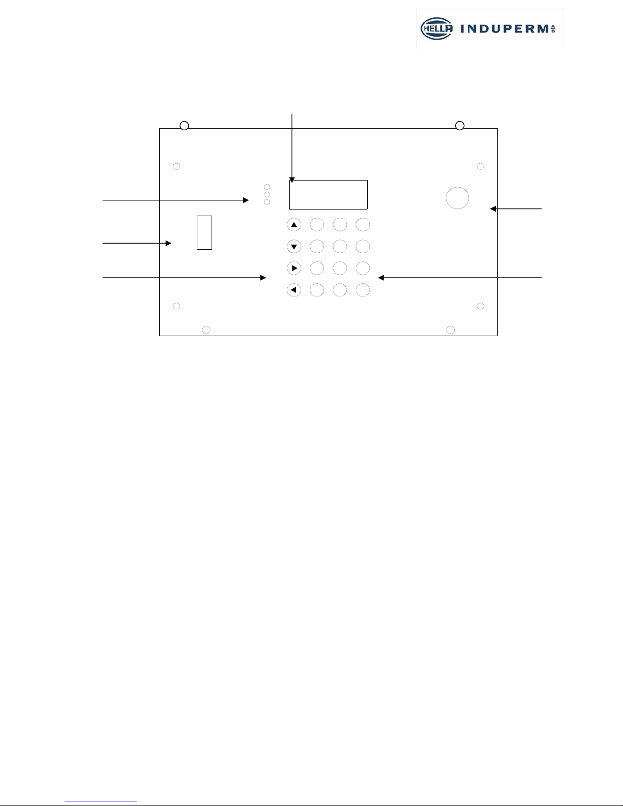
3.3 Operating Description
1. LED
2. Communication port
3. Arrow keys
4. LCD display
5. Key switch
6. The keys 0-9 + E & C
1. LED: RED (top) – YELLOW (in the middle) – GREEN (bottom)
RED:
A flashing red LED indicates that the regulator is in either ‘manual’ or ‘turned off’.
Constant light in the red diode indicates that there is some kind of an alarm.
YELLOW:
Constant light in the yellow diode indicates that the earth error measuring is active.
A flash every two. seconds indicates that the earth error measuring is disconnected permanently.
GREEN:
The light in the green diode means, that the actual current in the serial circuit is equal to the
“Should-Be” value 0.4A.
This means that the green light will turn off shortly when switching and changing the level of the
current.
The green diode will for instance be turned off if there are so many defect lights in the circuit that
the regulator reserves are not sufficient to give the required current value at the relevant level
(most often the 100% level).
INDUPERM CCR 961
TEST
Aus
Fernsteuerung Manuell
E0
C
987
4
123
56
1
2
3
4
5
6

CCR961 MANUAL-GB
15
Version B2:01-07-2015
If the green light is off for more than 1-5 seconds (adjustable), the step back-indication to the
remote control will disappear.
2. On the communication port the oscilloscope or the PC can be connected to read out values from
the regulator.
3. The arrow keys are used to navigate the menus on the regulator. The arrow keys have other
functions as well in the individual menus.
4. LCD display:
Here you see a number of parameters such as:
-Analogue values
-General information
-And directions for potential activities
5. The key switch has three positions: Remote control – Turned off – Manual control.
-REMOTE CONTROL (FERN)
When the key switch is in Remote control mode, the regulator can be switched-on and off,
and light intensity step can be selected from the Remote Control System.
-TURNED OFF (AUS)
When the key switch is turned off, it means that the regulator can be controlled neither
from the keyboard nor from the remote control.
-MANUAL CONTROL (MANUAL)
When the key switch is in Manual control mode, the regulator can be controlled by way of
the keyboard on the regulator.
Back-indications, alarms and analogue values will, however, still be send to the remote
control system.
When you switch from Remote control mode to Manual control mode, you have to pass
the Turned off position. To prevent the regulator from switching-off, the key switch must
be turned quickly past turned off. The regulator will stay at the level to which it has been
connected from the remote control.
When you switch from Manual control mode to Remote control mode, you have to pass
the Turned off position. To prevent the regulator from switching-off, the key switch must
be turned quickly past turned off. The regulator will switch to the intensity level selected
from the remote control.
You change between the ordinary menus by using the arrow keys (), irrespective of
the position of the key switch without affecting the setting of the light.
You can for instance browse forward to Menu 3 (ISO Mess. circuit) and activate a
measurement.
6. The keys 0-9 + E & C:
The keys 0-7 can be used to switch-on or off in light intensity levels 1-7 where 0 is used for
switching-off.
When pressing a key between 0-7 above the max number of steps to which the regulator is set, the
regulator will connect to the 100% level.
The keys 0-9 are also used for indicating new values, e.g. in the adjusting mode.

CCR961 MANUAL-GB
16
Version B2:01-07-2015
Press the E key to get into the adjusting mode. The key is moreover used for acknowledging.
The 0 key is used to resetting any alarms. The key switch must be in the OFF position.
The most frequent adjustments are described in the Step-by-Step instruction.
3.4 The menu’s
There are more menu areas:
Normal menu (no access code needed) with the menu’s N1 – N12
User menu (user code) with the menu’s U1 – U 21
Factory menu (factory code) with the menu’s F1 – F19
Normal menu is only for display of data, while User and Factory menu are for setting and
adjustment of the CCR.
Below is given information about what can be read and done by means of the Normal menu, while
information about settings and possibilities in User and factory menus are given in section 5.2.
Normal menu:
Menu
no.
Menu information Eventual special function
N1 Series circuit name
Actual output current
Actual selected intensity
step
Remote – Off – local
operation selected
Press > <:
Lower text line shows: 10/(500-XXX), where
XXX is the actual trigger firing position (called “pyk).
The CCR always returns to this menu (after 2 min.).
Press > <:
Lower text line shows current mode, ISO mode and RS485
address
Press > E <:
Brings you directly to menu N7
N2 Actual output current
Actual output voltage
Actual input voltage
Actual output power
Press > E <:
When the CCR is set to “Learn” for lamp supervision (see 5.3.11)
it will automatically note and store the Z-value for each step (Z =
Uout / Iout)
N3 Lamp Alarm
No. of faulty lamps
Press > E <:
N4 Circuit Isolation
Last found value (can be 3
hours old)
Measuring active or off
Press > < :
Activates a new isolation measurement (also with CCR in Remote
Control).
N5 Hour count
Total in 100% step
Total for all steps
System Temperature in °C
N6 CCR961 SW version
Time
Date
RS485 address (node)
N7 Adjustment?
Enter Code
If you want to go to user or factory menu, enter the code and
press > E <

CCR961 MANUAL-GB
17
Version B2:01-07-2015
3.5 Power Transformer
Standard sizes are as follows: 2,2 - 3 – 5 – 7,5 – 10 – 12,5 – 15 – 20 – 25 – 30 - 35kVA.
The Transformers are, as standard, available for 230V or 400V. For all types larger than 20 kVA,
the standard is 400V. Other primary voltages upon request.
As our standard is preferred the 400V series, as the total losses for the CCR are less than for the
230V series.
The transformers are constructed with two coils, each with a primary and a secondary side.
The two primary windings are, as standard connected in parallel, so each winding only have to be
calculated for 50% of the nominal primary current.
It is possible to change the primary windings from parallel to series, if the following conditions
are observed:
A transformer for 230V can be used for 400V primary voltage with the two
primary windings in series.
For a transformer with a rating more than twice the actual needed load, it is
an advantage to connect the two windings in series for better adjustment to
the load. Max. Load is only 50 % of nominal load.
The secondary winding is with several tappings for adjustment to actual load.
The two secondary windings are always connected in series.
The transformers are air-cooled.
POWER TRANSFORMER
NETZ 230 /400V
SERIENKREIS

CCR961 MANUAL-GB
18
Version B2:01-07-2015
4CCR installation
4.1 Unpacking the CCR shipment
The CCR’s are supplied on a pallet, and covered in a plywood box.
Remove the screws in the top and bottom of the plywood box, and the box can be lifted off the
CCR pallet, and folded.
The CCR cubicle are bolted to the pallet. Remove the bolts and eventual additional transport
support for the output transformer and the CCR cubicle can be removed from the pallet.
4.2 Before the installation
Check the planned installation location. The floor must be stable, and the CCR cubicle must
be fastened to the floor. The room must be ventilated and free air circulation from under the
cubicle must be secured. If this cannot be guaranteed, a special front door with air-inlets must
be ordered.
The CCR cubicles can be placed directly next to another, and as all services can be performed
from the front the CCR cubicle can be placed with the backside directly to a wall.
4.3 CCR installation

CCR961 MANUAL-GB
19
Version B2:01-07-2015
CCR front view

CCR961 MANUAL-GB
20
Version B2:01-07-2015
Comments:
Remote connection for RS485 can be by means of terminals or RJ45 plugs
Input power cable dimension must be according to calculated max. input current
Series circuit cables must be connected by means of cable shoes, and these are normally
included in the delivery (mounted on lightning arrestors)
Table of contents
Popular Safe manuals by other brands


Genie Hand
Genie Hand MMH Series User instructions

First Alert
First Alert 2087F-BD Operations & installation guide

Honeywell
Honeywell 2050 Operatin & installation guide

First Alert
First Alert 2087F-BD Operations & installation guide

Sealey
Sealey SKS01 quick start guide

Homak
Homak FIRST WATCH HS10520802 Owner's manual & operating instructions


