Helmer UltraCW User manual
360113-1/A
UltraCW™ Version B
Model UltraCW™
S/N
HELMER, INC. 15425 HERRIMAN BLVD., NOBLESVILLE, IN 46060 USA
PHONE (317) 773-9073 FAX (317) 773-9082
USA and CANADA (800) 743-5637
www.helmerinc.com
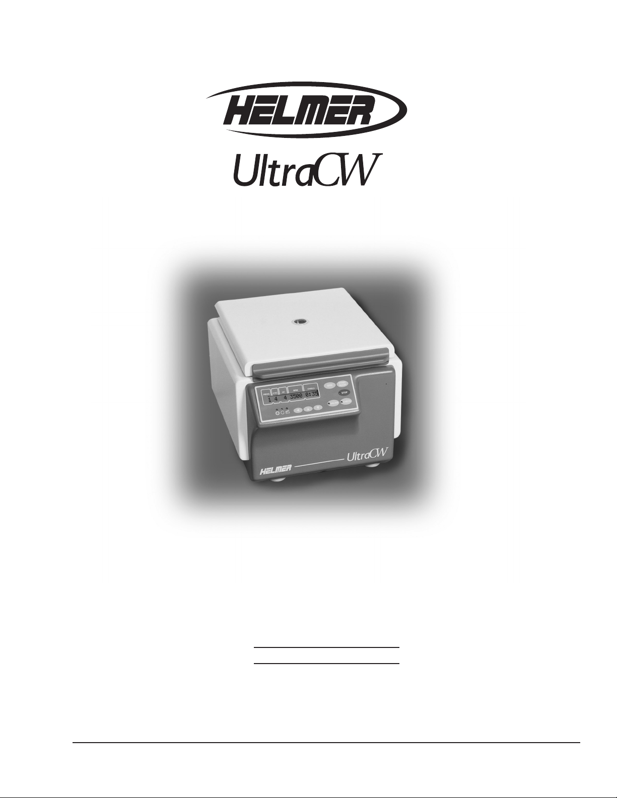
Automatic Cell Washing System
Service Manual
TM

i
360113-1
Aboutthismanual...........................................................ii
1 Workingsafely...........................................................1
1.1 Generalsafety....................................................................1
1.2 Electricalsafety...................................................................1
1.3 Chemicalandbiologicalsafety .......................................................1
2 Reviewing information about your cell washer. . . . . . . . . . . . . . . . . . . . . . . . . . . . . . . . .2
2.1 Findingmodelandinputpowerinformation..............................................2
2.2 Finding software and part version information ............................................2
3 Troubleshooting..........................................................3
3.1 Troubleshootinggeneraloperationproblems.............................................3
3.2 Addressingerrormessages..........................................................4
4 Servicingthecellwasher .................................................15
4.1 Testing whether the rotor speed is within the design tolerance . . . . . . . . . . . . . . . . . . . . . . . . . . . . . .15
4.2 Testing whether the imbalance value is in the permissible range . . . . . . . . . . . . . . . . . . . . . . . . . . . .16
4.3 Adjusting the imbalance microswitch ..................................................17
4.4 Removing and installing the front panel................................................18
4.5 Adjustingthedisplaycontrast .......................................................19
4.6 Viewingandchangingthellspeed...................................................20
4.7 Replacingthefrequencyconverter ...................................................21
4.7.1 Settingjumpers.........................................................22
4.7.2 Initializing the cell washer.................................................22
4.8 Removing and installing the bowl assembly ............................................23
4.9 Performingpost-repairchecks.......................................................25
5 Parts ..................................................................26
5.1 Partsonthefrontandlid ...........................................................26
5.2 Partsontherearandbottom........................................................27
5.3 Partsontheside .................................................................27
5.4 Partsonthebowlandrotor.........................................................28
5.5 Partsbehindthefrontpanel.........................................................29
5.6 Partsbehindtherearpanel.........................................................30
5.7 Partsunderthebowl ..............................................................31
5.8 Accessories.....................................................................33
6 Schematic..............................................................34
Contents
Contents

ii
360113-1
UltraCW™ Automatic Cell Washing System Service Manual
About this manual
Welcome to the UltraCW™ Automatic Cell Washing System Service Manual. This section explains the symbols and
conventions used in this manual, copyright information about this document, and trademark information for products
supplied by Helmer.
Intended audience
This manual is intended for use by qualied service technicians. This manual is to be used in conjunction with the
UltraCW™ Automatic Cell Washing System Operation Manual.
Symbols and conventions
Several symbols and conventions are used in this manual.
Warnings
A Warning is used to call attention to a condition or possible situation that could cause injury to the operator.
Warnings are identied as follows:
!
WARNING: This is a sample of a warning: Follow all chemical handling and disposal
requirements and procedures that are specied by your organization.
Cautions
A Caution is used to call attention to a condition or possible situation that could damage or destroy the equipment or the
operator’s work.
Cautions are identied as follows:
!
CAUTION: This is a sample of a caution: Be sure that the tubing is free of obstructions.
Blocked tubing can cause uid to back up and cause motor failure.
Notes
Notes contain additional information about a topic. Notes are used to provide information about how a topic relates to another
topic, or background information about a design characteristic.
Notes are identied as follows:
NOTE: This is a sample of a note: Tubing kits are available for purchase through
Helmer.
Copyright and trademark information
Copyright © 2006 Helmer, Inc.
UltraCW™ is a registered trademark of Helmer, Inc. in the United States of America.
All other trademarks and registered trademarks are the property of their respective owners.
1
360113-1
Working safely
1 Working safely
This section describes general safety information for servicing the UltraCW Automatic Cell Washing
System (“cell washer”). The Operation Manual includes additional safety information for operating and
cleaning the cell washer. Your organization may provide additional safety information.
1.1 General safety
To avoid injury to yourself and the cell washer, follow these safety instructions:
► Do not use the cell washer if its components are damaged.
► Never attempt to physically restrict any of the moving components.
► Do not move or bump the cell washer during operation.
► Before performing the procedures in this manual, review the specic safety instructions for them.
► Before using tools, materials, and equipment to perform procedures in this manual, review the
manufacturer’s safety instructions for them.
► Perform only the maintenance described in this manual. Maintenance other than that specied in this
manual should only be performed by technical service representatives authorized by Helmer.
1.2 Electrical safety
!
WARNING: The cell washer has the potential of being a shock hazard. Review all safety
instructions.
Review the following safety instructions before troubleshooting, repairing, or replacing parts in the cell
washer:
► Before removing covers from the cell washer, disconnect the power to the cell washer.
► Use appropriate grounding precautions when replacing circuit boards and other electrical parts.
► Use power cords and other electrical parts that are designed for use with the cell washer.
1.3 Chemical and biological safety
Review the safety instructions in the Operation Manual before using, cleaning, or servicing the cell washer.
!
WARNING: In addition to the instructions included in this manual and the Operation Manual,
follow all chemical handling and disposal requirements and procedures specied
by your organization.
Before sending parts to Helmer or your distributor for service or repair,
decontaminate them as appropriate. Any items that have not been
decontaminated appropriately will not be accepted. Documentation stating
that the contents are not contaminated and are safe to handle must accompany
all returns. Contact Helmer for decontamination instructions and a return
authorization number.
2
360113-1
UltraCW™ Automatic Cell Washing System Service Manual
2 Reviewing information about
your cell washer
This section explains how to nd identication information about your cell washer.
2.1 Finding model and input power information
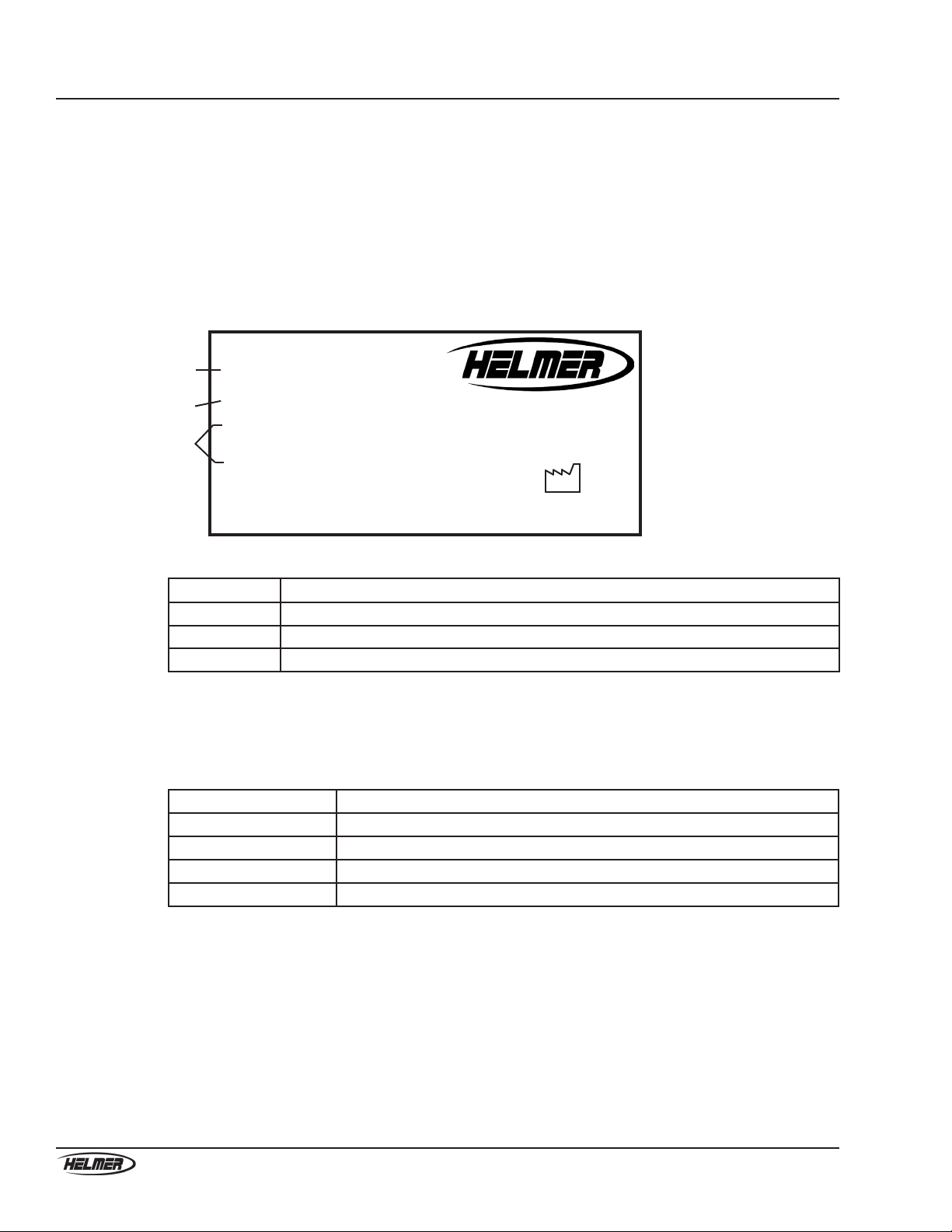
The Product Specication label is located on the right side of the cell washer next to the power connector.
A
B
C
Type: UltraCW
Serial Number 0000000
Volts Freq Amps Power
110-127Vac 60 Hz 2.5 200 Watts
Kinetic Energy Max. Density RPM
250Nm 1.2Kg/dm 3500R/min
3Made in Switzerland
2005
www.helmerinc.com
Noblesville, IN USA
ProductSpecicationlabel(sample)
Label Description
AType (Model)
B Serial number (S/N)
CPower requirements
2.2 Finding software and part version information
The software version appears on the control panel when you turn on the power.
Additional information is available through the Global menu, as follows:
Parameter Meaning
CONTROL: XXX h Number of operating hours
VERS XX °C/* 00 XX is the software version
FU/CCI - 1001 Frequency converter type
FU/CCI - S. XX.XX Frequency converter software version
To view version information in the Global menu
1 On the control panel, press and hold the parameter selection button () for about eight seconds until
VOLUME ADJUST XX appears on the message screen.
2 Press and release the parameter selection button () to cycle through the global parameters.
3 Exit the Global menu by pressing the STOP button or by not pressing any of the buttons for
approximately 16 seconds. The message screen returns to display mode for the selected program.
3
360113-1
Troubleshooting
3 Troubleshooting
Before taking actions as described in this section, make sure that operational issues have been addressed as
described in the Operation Manual. Also, be sure that the cell washer operator has followed the appropriate
laboratory procedures and used the appropriate materials for the task.
This section describes some problems you may experience, explains possible causes, and provides actions
you can take to correct them.
!
WARNING: Review all safety instructions prior to completing troubleshooting
recommendations. For more information, see Section 1, “Working safely.”
3.1 Troubleshooting general operation problems
Problem Possible Cause Action
The cell washer is
turned on, but nothing
is displayed on the
message screen.
There is no power to the
cell washer.
1 Verify that the outlet is operational.
2 Try the following tasks in order, testing after
each to determine if it solved the problem:
a Replace the fuse.
b Replace the main power switch.
c Replace the transformer.
d Replace the RFI lter.
The display contrast is
set too low.
► Adjust the display contrast. For instructions,
see Section 4.5, “Adjusting the display
contrast.”
A part in the LCD circuit
is faulty.
► Try the following tasks in order, testing after
each to determine if it solved the problem:
1 Replace the control panel.
2 Replace the power supply board.
During a saline check,
the pump is not making
any sound and saline is
not being dispensed.
A part in the pump
system is faulty.
► Remove the pump tubing from the pump. With
the pump tubing removed, perform a saline
check.
► If the pump does not operate, replace the
pump.
► If the pump does operate, replace the
pump tubing, which may have hardened
over time.
During a saline check,
the pump is operating,
but saline is not being
dispensed correctly.
A part in the liquid
handling system circuit
is faulty.
► Try the following tasks in order, testing after
each to determine if it solved the problem:
1 Replace the ow meter.
2 Replace the liquid handling board.
The tubes were not
decanted when they
were programmed to
do so.
The rotor is faulty. ► Verify that all the rotor locks (decant hooks)
are intact. If any are broken off or damaged,
replace the rotor.
A part in the motor
circuit is faulty.
► Try the following tasks in order, testing after
each to determine if it solved the problem:
1 Replace the motor.
2 Replace the frequency converter. For
instructions, see Section 4.7, “Replacing
the frequency converter.”
3 Replace the power supply board.

4
360113-1
UltraCW™ Automatic Cell Washing System Service Manual
Problem Possible Cause Action
The rotor speed seems to
be too high or too low.
A part in the speed
sensor circuit is faulty.
1 Measure the rotor speed. For instructions, see
Section 4.1, “Testing whether the rotor speed is
within the design tolerance.”
2 Try the following tasks in order, testing after
each to determine if it solved the problem:
a Replace the speed sensor.
b Replace the motor.
c Replace the frequency converter. For
instructions, see Section 4.7, “Replacing
the frequency converter.”
Tubes are breaking
during processes with a
Decant step.
Tube holder inserts were
not installed correctly
before processing
10 mm x 75 mm tubes.
► Install the tube holder inserts, and repeat
the process to determine if the problem was
solved.
The top of the tube does
not move freely around
the ll port.
► Ensure that the height of the tubes is within the
acceptable tolerance of 75 mm ± 1.5 mm.
3.2 Addressing error messages
In the event of an error condition, the cell washer displays an error message to assist in troubleshooting.
This section provides possible causes associated with each error message and actions that should be taken.
XX represents the error message number.
CONTROL - ERROR XX
When a message of this type appears, there is a problem with the lid closing or locking, or a problem with
the control panel.
Error
message
number
Possible cause Action
04,
06 to 09
Continued
The lid lock is faulty. 1 Clear the error message: Open the lid, then
turn off the power. After about 10 seconds, turn
the power back on.
2 Check if the lid can be opened while the cell
washer is turned off. If it can, replace the lid
lock.
A connection in the lid lock circuit is
loose.
1 Clear the error message: Open the lid, then
turn off the power. After about 10 seconds, turn
the power back on.
2 Check the contact connection between the lid
lock and the control/display board.
3 Check that the ribbon cable between the
control/display board and the power supply
board is securely connected.

5
360113-1
Troubleshooting
Error
message
number
Possible cause Action
Continued
04,
06 to 09
A part in the lid lock circuit is faulty. 1 Clear the error message: Open the lid, then
turn off the power. After about 10 seconds, turn
the power back on.
2 Try the following tasks in order, testing after
each to determine if it solved the problem:
a Replace the ribbon cable between the
control/display board and the power
supply board.
b Replace the power supply board.
c Replace the control panel.
21 to 26 The control panel is faulty. 1 Clear the error message: Open the lid, then
turn off the power. After about 10 seconds, turn
the power back on.
2 Replace the control panel.
FU/CCI - ERROR XX
When a message of this type appears, there is a problem related to the frequency converter.
Error
message
number
Possible cause Action
60 A part in the frequency converter
circuit is faulty, resulting in a false lid
lock release signal.
► Try the following tasks in order, testing after
each to determine if it solved the problem:
1 Replace the ribbon cable between the
control/display board and the power
supply board.
2 Replace the ribbon cable between the
frequency converter and the power supply
board.
3 Replace the frequency converter. For
instructions, see Section 4.7, “Replacing
the frequency converter.”
4 Replace the power supply board.
5 Replace the control panel.
61 A part in the frequency converter
circuit is faulty, resulting in a
processing error.
1 Clear the error message: Open the lid, then
turn off the power. After about 1 minute, turn
the power back on.
2 Try the following tasks in order, testing after
each to determine if it solved the problem:
a Replace the ribbon cable between the
control/display board and the power
supply board.
b Replace the ribbon cable between the
frequency converter and the power supply
board.
c Replace the frequency converter. For
instructions, see Section 4.7, “Replacing
the frequency converter.”
d Replace the power supply board.
e Replace the control panel.

6
360113-1
UltraCW™ Automatic Cell Washing System Service Manual
Error
message
number
Possible cause Action
62 The main supply voltage is too low,
resulting in an undervoltage condition
to the frequency converter.
1 Clear the error message: Open the lid, then
turn off the power. After about 1 minute, turn
the power back on.
2 Verify that the outlet in the facility is
operational and supplying adequate voltage to
the cell washer.
3 Try the following tasks in order, testing after
each to determine if it solved the problem:
a Replace the ribbon cable between the
control/display board and the power
supply board.
b Replace the ribbon cable between the
frequency converter and the power supply
board.
c Replace the frequency converter. For
instructions, see Section 4.7, “Replacing
the frequency converter.”
d Replace the power supply board.
e Replace the control panel.
63 A part in the frequency converter
circuit is faulty, resulting in an
overcurrent condition in the motor.
1 Clear the error message: Open the lid, then
turn off the power. After about 1 minute, turn
the power back on.
2 Try the following tasks in order, testing after
each to determine if it solved the problem:
a Replace the motor.
b Replace the ribbon cable between the
frequency converter and the power supply
board.
c Replace the frequency converter. For
instructions, see Section 4.7, “Replacing
the frequency converter.”
d Replace the power supply board.
64 A part in the frequency converter
circuit is faulty, resulting in an
overvoltage condition in the braking
resistor.
1 Clear the error message: Open the lid, then
turn off the power. After about 1 minute, turn
the power back on.
2 Try the following tasks in order, testing after
each to determine if it solved the problem:
a Replace the braking resistor.
b Replace the ribbon cable between the
frequency converter and the power supply
board.
c Replace the frequency converter. For
instructions, see Section 4.7, “Replacing
the frequency converter.”
d Replace the power supply board.
7
360113-1
Troubleshooting
Error
message
number
Possible cause Action
67 A part in the frequency converter
circuit is faulty, resulting in an
overtemperature condition in the
motor.
1 Clear the error message: Open the lid, then
turn off the power. After about 1 minute, turn
the power back on.
2 Try the following tasks in order, testing after
each to determine if it solved the problem:
a Test the motor windings. If they are faulty,
replace the motor.
b Replace the ribbon cable between the
frequency converter and the power supply
board.
c Replace the frequency converter. For
instructions, see Section 4.7, “Replacing
the frequency converter.”
d Replace the power supply board.
68 A part in the frequency converter
circuit is faulty, resulting in an
overvoltage condition in the
frequency converter.
1 Clear the error message: Open the lid, then
turn off the power. After about 1 minute, turn
the power back on.
2 Conrm that the ambient temperature during
operation does not exceed 45 °C.
3 Try the following tasks in order, testing after
each to determine if it solved the problem:
a Replace the ribbon cable between the
control/display board and the power
supply board.
b Replace the ribbon cable between the
frequency converter and the power supply
board.
c Replace the frequency converter. For
instructions, see Section 4.7, “Replacing
the frequency converter.”
d Replace the power supply board.
69 The frequency converter is faulty. 1 Clear the error message: Open the lid, then
turn off the power. After about 1 minute, turn
the power back on.
2 Replace the frequency converter. For
instructions, see Section 4.7, “Replacing the
frequency converter.”
84 A part in the frequency converter
circuit is faulty, resulting the
frequency converter detecting excess
rotor speed.
► Try the following tasks in order, testing after
each to determine if it solved the problem:
1 Replace the ribbon cable between the
frequency converter and the power supply
board.
2 Replace the frequency converter. For
instructions, see Section 4.7, “Replacing
the frequency converter.”
3 Replace the power supply board.
8
360113-1
UltraCW™ Automatic Cell Washing System Service Manual
Error
message
number
Possible cause Action
85 A part in the frequency converter
circuit is faulty, resulting in a
processing error.
1 Clear the error message: Open the lid, then
turn off the power. After about 10 seconds, turn
the power back on.
2 Try the following tasks in order, testing after
each to determine if it solved the problem:
a Replace the ribbon cable between the
frequency converter and the power supply
board.
b Replace the frequency converter. For
instructions, see Section 4.7, “Replacing
the frequency converter.”
c Replace the power supply board.
IMBALANCE
When this message appears, there is a problem with the balance of the rotor.
Error
message
number
Possible cause Action
None
Continued
The Imbalance initialization
parameter was set to the wrong value
after the frequency converter was
replaced.
1 Clear the error message: Open the lid, then
turn off the power. After about 10 seconds, turn
the power back on.
2 Check that the Imbalance parameter is set
to 2. For more information and instructions,
see Section 4.7 “Replacing the frequency
converter.”
The imbalance tolerance is set too
low.
1 Clear the error message: Open the lid, then
turn off the power. After about 10 seconds, turn
the power back on.
2 Check the imbalance tolerance and adjust it
if necessary. For instructions, see Section 4.2,
“Testing whether the imbalance value is in the
permissible range.”
A connection in the imbalance
microswitch circuit is loose.
1 Clear the error message: Open the lid, then
turn off the power. After about 10 seconds, turn
the power back on.
2 Check the connection between the imbalance
microswitch and the power supply board.
3 Check that the ribbon cable between the
control/display board and the power supply
board is securely connected.

9
360113-1
Troubleshooting
Error
message
number
Possible cause Action
Continued
None
A part in the imbalance microswitch
circuit is faulty
1 Clear the error message: Open the lid, then
turn off the power. After about 10 seconds, turn
the power back on.
2 Try the following tasks in order, testing after
each to determine if it solved the problem:
a Check the continuity of the imbalance
microswitch, which is normally closed.
The resistance should be 0 Ω when the
switch is closed (not activated). If there
is resistance, replace the imbalance
microswitch, then set the imbalance
tolerance. For instructions, see Section 4.3,
“Adjusting the imbalance microswitch.”
b Replace the ribbon cable between the
control/display board and the power
supply board.
c Replace the power supply board.
d Replace the control panel.
LOW SALINE
When this message appears, there is a problem with the ow of saline into the cell washer.
Error
message
number
Possible cause Action
None A connection in the liquid handling
system circuit is loose.
1 Clear the error message: Open the lid, then
turn off the power. After about 10 seconds, turn
the power back on.
2 Check the connection between the liquid
handling board and the power supply board.
A part in the pump system is faulty. 1 Clear the error message: Open the lid, then
turn off the power. After about 10 seconds, turn
the power back on.
2 Remove the pump tubing from the pump. With
the pump tubing removed, perform a saline
check.
► If the pump does not operate, replace the
pump.
► If the pump does operate, replace the
pump tubing, which may have hardened
over time.
A part in the liquid handling system
circuit is faulty.
1 Clear the error message: Open the lid, then
turn off the power. After about 10 seconds, turn
the power back on.
2 Try the following tasks in order, testing after
each to determine if it solved the problem:
a Replace the ow meter.
b Replace the liquid handling board.

10
360113-1
UltraCW™ Automatic Cell Washing System Service Manual
N > MAX XX
When this message appears, the rotor speed being detected exceeds the maximum allowable speed.
Error
message
number
Possible cause Action
05 The insulation on the speed sensor
cable is faulty.
1 Clear the error message: Turn off the power.
After about 10 seconds, turn it back on.
2 Check the speed sensor cable for wear. If worn,
replace the speed sensor.
A connection in the speed sensor
circuit is loose.
1 Clear the error message: Turn off the power.
After about 10 seconds, turn it back on.
2 Check the connection between the speed
sensor and the power supply board.
3 Check that the ribbon cable between the
control/display board and the power supply
board is securely connected.
A part in the speed sensor circuit is
faulty.
1 Clear the error message: Turn off the power.
After about 10 seconds, turn it back on.
2 Try the following tasks in order, testing after
each to determine if it solved the problem:
a Test the speed sensor by measuring the
rotor speed. For instructions, see Section
4.1, “Testing whether the rotor speed is
within the design tolerance.” If the speed
is not within the tolerance, replace the
speed sensor.
b Replace the ribbon cable between the
control/display board and the power
supply board.
c Replace the ribbon cable between the
frequency converter and the power supply
board.
d Replace the frequency converter. For
instructions, see Section 4.7, “Replacing
the frequency converter.”
e Replace the power supply board.
f Replace the control panel.

11
360113-1
Troubleshooting
N < MIN XX
When this message appears, the rotor is rotating too slowly.
Error
message
number
Possible cause Action
13 A connection in the motor circuit is
loose.
1 Clear the error message: Open the lid, then
turn off the power. After about 10 seconds, turn
the power back on.
2 Check the connection between the motor and
the frequency converter.
A part in the motor circuit is faulty. 1 Clear the error message: Open the lid, then
turn off the power. After about 10 seconds, turn
the power back on.
2 Try the following tasks in order, testing after
each to determine if it solved the problem:
a Test the motor windings. If they are faulty,
replace the motor.
b Replace the frequency converter. For
instructions, see Section 4.7, “Replacing
the frequency converter.”
POWER INTERRUPT
When this message appears, the AC power was interrupted during operation, or was sensed as being
interrupted.
Error
message
number
Possible cause Action
None A connection between the control/
display board and the power supply
board is loose.
1 Clear the error message: Open the lid then
press the START WASH button.
2 Check the connection between the control/
display board and the power supply board.
A part in the control panel and power
supply circuit is faulty.
1 Clear the error message: Open the lid then
press the START WASH button.
2 Try the following tasks in order, testing after
each to determine if it solved the problem:
a Replace the power supply board.
b Replace the ribbon cable between the
control/display board and the power
supply board.
c Replace the control panel.
12
360113-1
UltraCW™ Automatic Cell Washing System Service Manual
SER I/O - ERROR XX
When a message of this type appears, there is a problem with communication between components.
Error
message
number
Possible cause Action
30 and 31 A connection in the frequency
converter circuit is loose.
1 Clear the error message: Turn off the power.
After about 10 seconds, turn it back on.
2 Check the connection between the frequency
converter and the power supply board.
3 Check the connections between the frequency
converter and the RFI lter and braking
resistor overtemperature switch.
The connections between the
frequency converter and the RFI lter
and braking resistor overtemperature
switch are wrong.
1 Clear the error message: Turn off the power.
After about 10 seconds, turn it back on.
2 Check that the connections on the frequency
converter at connector S102 are correct.
The braking resistor overtemperature
switch has opened.
1 Clear the error message: Turn off the power.
After about 10 seconds, turn it back on.
2 Replace the braking resistor overtemperature
switch.
A part in the frequency converter
circuit is faulty.
1 Clear the error message: Turn off the power.
After about 10 seconds, turn it back on.
2 Try the following tasks in order, testing after
each to determine if it solved the problem:
a Replace the frequency converter. For
instructions, see Section 4.7, “Replacing
the frequency converter.”
b Replace the ribbon cable between the
control/display board and the power
supply board.
c Replace the ribbon cable between the
frequency converter and the power supply
board.
d Replace the control panel.
e Replace the power supply board.
33, 34, and
36
A part in the frequency converter and
control panel circuit is faulty.
1 Clear the error message: Turn off the power.
After about 10 seconds, turn it back on.
2 Try the following tasks in order, testing after
each to determine if it solved the problem:
a Replace the frequency converter. For
instructions, see Section 4.7, “Replacing
the frequency converter.”
b Replace the ribbon cable between the
control/display board and the power
supply board.
c Replace the ribbon cable between the
frequency converter and the power supply
board.
d Replace the control panel.
e Replace the power supply board.
13
360113-1
Troubleshooting
TACHO - ERROR XX
When a message of this type appears, the rotor is not installed, or the speed is being controlled or sensed
incorrectly.
Message
number
Possible cause Action
01 A connection in the speed sensor
circuit is loose, resulting in the
interruption of speed sensor pulses.
1 Clear the error message by doing the
following:
a Open the lid, then turn off the power.
b While spinning the rotor clockwise by
hand, turn on the power.
2 Check the connection between the speed
sensor and the power supply board.
A part in the speed sensor circuit is
faulty.
1 Clear the error message by doing the
following:
a Open the lid, then turn off the power.
b While spinning the rotor clockwise by
hand, turn on the power.
2 Try the following tasks in order, testing after
each to determine if it solved the problem:
a Test the speed sensor by measuring the
rotor speed. For instructions, see Section
4.1, “Testing whether the rotor speed is
within the design tolerance.” If the speed
is not within the tolerance, replace the
speed sensor.
b Replace the ribbon cable between the
control/display board and the power
supply board.
c Replace the ribbon cable between the
frequency converter and the power supply
board.
d Replace the frequency converter. For
instructions, see Section 4.7, “Replacing
the frequency converter.”
e Replace the control panel.
f Replace the power supply board.

14
360113-1
UltraCW™ Automatic Cell Washing System Service Manual
Message
number
Possible cause Action
02 A connection in the speed sensor and
motor circuit is loose, resulting in no
speed sensor pulses after start-up.
1 Clear the error message by doing the
following:
a Open the lid, then turn off the power.
b While spinning the rotor clockwise by
hand, turn on the power.
2 Check the connection between the speed
sensor and the power supply board.
3 Check the motor connections.
A part in the speed sensor and motor
circuit is faulty.
1 Clear the error message by doing the
following:
a Open the lid, then turn off the power.
b While spinning the rotor clockwise by
hand, turn on the power.
2 Try the following tasks in order, testing after
each to determine if it solved the problem:
a Test the motor windings. If they are faulty,
replace the motor.
b Test the speed sensor by measuring the
rotor speed. For instructions, see Section
4.1, “Testing whether the rotor speed is
within the design tolerance.” If the speed
is not within the tolerance, replace the
speed sensor.
c Replace the ribbon cable between the
control/display board and the power
supply board.
d Replace the ribbon cable between the
frequency converter and the power supply
board.
e Replace the frequency converter. For
instructions, see Section 4.7, “Replacing
the frequency converter.”
f Replace the control panel.
g Replace the power supply board.
VERSION - ERROR XX
When a message of this type appears, there is a problem with the control panel.
Message
number
Possible cause Action
12 The cell washer was not initialized
after replacing the frequency
converter.
1 Clear the error message: Turn off the power.
After about 10 seconds, turn it back on.
2 Initialize the cell washer. For instructions, see
Section 4.7.2, “Initializing the cell washer.”
Reset the power to clear the error message.
A component on the control panel is
not compatible with the frequency
converter.
1 Clear the error message: Turn off the power.
After about 10 seconds, turn it back on.
2 Replace the control panel.
15
360113-1
Servicing the cell washer
4 Servicing the cell washer
This section explains how to access serviceable parts, as well as how to perform some service procedures.
4.1 Testing whether the rotor speed is within the
design tolerance
NOTE: You cannot test the decant speed, but you can change it by changing a global
parameter value. For instructions, refer to the Operation Manual.
You can measure the rotor speed to determine whether it is within the design tolerance.
The cell washer has a sight window in the lid and an optical reference on the rotor so that you can easily
measure the speed of the rotor during operation.
When the rotor is programmed to spin at 3500 r/min (RPM), the measured speed should be
3500 r/min ± 20 r/min.
For more information and instructions to program and use the cell washer, refer to the Operation Manual.
You will need the following to test the rotor speed:
► Laser tachometer (calibrated and capable of measuring r/min)
!
WARNING: Prior to using the laser tachometer, review all safety and usage instructions
provided by the manufacturer.
To test whether the rotor speed is within the design tolerance
NOTE: Regulations for your organization may recommend test methods different from
what appear here. Use the appropriate methods for your organization.
1 Install the rotor.
2 Program the Spin (S) program with a spin speed of 3500 r/min and a spin time that is long enough for
you to measure the speed.
3 Start the Spin (S) program by pressing the SPIN button.
4 While the rotor is spinning and 3500 is displayed on the message screen, point the tachometer’s laser
beam through the sight window on the lid. As the rotor spins, the laser momentarily reects off the
optical reference on the rotor.
5 Obtain the reading from the tachometer. If the speed is not within the tolerance of 3500 r/min ± 20
r/min, follow the appropriate troubleshooting steps to determine how to proceed.

16
360113-1
UltraCW™ Automatic Cell Washing System Service Manual
4.2 Testing whether the imbalance value is in the
permissible range
The imbalance microswitch senses whether the rotor is balanced during operation. If the rotor is not
balanced, an imbalance error results. The weight at which the imbalance error occurs is the imbalance
value.
At the factory, the microswitch is positioned to allow an imbalance value that lies between 5 g and 10 g
when the rotor is spinning at 1500 r/min. For example, if the imbalance value were 7 g (the middle of the
range), an imbalance error would result only if one side of the rotor were more than 7 g heavier than the
other. One gram is approximately equal to 1 ml of saline solution.
Continual operation of the cell washer when the imbalance value of greater than or equal to 10 g may
damage the cell washer. An imbalance value of less than or equal to 5 g is overly sensitive to the normal
variations in weight that occur during operation.
For more information and instructions to program and use the cell washer, refer to the Operation Manual.
You will need the following to test whether the imbalance value is in the permissible range:
► Tubes (enough to ll all available positions on the rotor)
► Saline solution. One test run requires 15 g (approximately 15 ml)
► Scale (calibrated and capable of measuring 10 g)
To test whether the imbalance value is in the permissible range
NOTE: Regulations for your organization may recommend test methods different from
what appear here. Use the appropriate methods for your organization.
1 Add tubes to all the available positions in the rotor. If you are using 10 mm x 75 mm tubes, conrm
that the tube inserts are installed correctly in all the tube holders.
2 Program the Spin (S) program with a spin speed of 1500 r/min and a spin time of 20 seconds.
3 Test whether the imbalance value is below the upper limit of the permissible range.
a Starting with empty tubes, add a total of 10 g of saline solution to one or more tubes on one side of
the rotor.
b Install the rotor.
c Start the Spin program. If the program completes without an imbalance error, then the imbalance
value is too high and must be decreased. For instructions, see Section 4.3, “Adjusting the
imbalance microswitch.”
4 Test whether the imbalance value is above the lower limit of the permissible range.
a Add a total of 5 g of saline solution to one or more tubes on one side of the rotor.
b Install the rotor.
c Start the Spin program. If an imbalance error occurs, then the imbalance value is too low and must
be increased. For instructions, see Section 4.3, “Adjusting the imbalance microswitch.”

17
360113-1
Servicing the cell washer
4.3 Adjusting the imbalance microswitch
NOTE: For more information about locating and identifying parts, see Section 5, “Parts”
and Section 6, “Schematic.”
The imbalance microswitch senses whether the rotor is balanced during operation. If the rotor is not
balanced, an imbalance error results.
The proximity of the microswitch to the motor shaft determines the value at which the rotor is considered
to be imbalanced. The higher the imbalance of the rotor, the closer the motor shaft moves toward the
microswitch during operation.
You may need to adjust the imbalance microswitch in the following circumstances:
► The imbalance value is outside of the permissible range.
► Imbalance errors continue to appear, even after you have addressed other possible causes.
► You replaced the imbalance microswitch.
You will need the following to adjust the position of the imbalance microswitch:
► #15 TORX® screwdriver
To adjust the imbalance microswitch
1 Remove the rotor from the cell washer, and close the lid.
2 Turn off the cell washer and disconnect it from power.
3 Turn the cell washer so that it rests on the left side.
4 On the bottom of the cell washer, use the screwdriver to loosen the screw in the slot. This screw
secures the imbalance microswitch bracket to the base.
Bottom of cell washer with imbalance adjustment screw circled
5 Do one of the following:
► To decrease the imbalance value, slide the screw toward the center of the cell washer. The switch
moves closer to the motor shaft.
► To increase the imbalance value, slide the screw away from the center of the cell washer. The
switch moves farther away from the motor shaft.
6 Tighten the screw to secure the imbalance bracket to the base.
7 Test the imbalance value to ensure that it in the permissible range. For instructions, see Section 4.2,
“Testing whether the imbalance value is in the permissible range.”
Other manuals for UltraCW
1
Table of contents
Other Helmer Washer manuals


