Helmer UltraCW User manual

TM
360084-1/H
UltraCW™ Version B
Model UltraCW™
S/N
HELMER, INC. 14395 BERGEN BLVD., NOBLESVILLE, IN 46060 USA
PHONE (317) 773-9073 FAX (317) 773-9082
USA and CANADA (800) 743-5637
www.helmerinc.com
Automatic Cell Washing System
Operation Manual

i
360084-1/H
About this manual ..........................................................iv
1 Workingsafely...........................................................1
1.1 Generalsafety....................................................................1
1.2 Electricalsafety...................................................................1
1.3 Chemicalandbiologicalsafety .......................................................2
2 Touring the cell washer ....................................................3
2.1 Touring the front, lid, and bowl ........................................................3
2.2 Touringtheside...................................................................4
2.3 Touringtherear...................................................................4
2.4 Touringthecontrolpanel............................................................5
2.5 Touring the rotor...................................................................6
3 Installing the cell washer. . . . . . . . . . . . . . . . . . . . . . . . . . . . . . . . . . . . . . . . . . . . . . . . . . .7
3.1 Recordingidenticationinformation....................................................7
3.2 Selecting an appropriate location......................................................7
3.3 Powering the cell washer ............................................................8
3.3.1 Installing the power cord...................................................8
3.3.2 Connecting to power......................................................8
3.3.3 Turningthepoweronandoff...............................................8
3.4 Openingandclosingthelid..........................................................9
3.5 Removingpackagingmaterials.......................................................9
3.6 Removing the transport bolts ........................................................10
3.7 Connecting to the saline supply and drain ..............................................11
3.7.1 Installing and removing the supply and drain tubing . . . . . . . . . . . . . . . . . . . . . . . . . . . . 11
3.7.2 Connectingtothesalinesupply............................................12
3.7.3 Connectingtothedrain ..................................................12
4 Programming the cell washer..............................................13
4.1 Understanding processes and process steps . . . . . . . . . . . . . . . . . . . . . . . . . . . . . . . . . . . . . . . . . . .13
4.1.1 Understanding processes.................................................13
4.1.2 Understanding process steps ..............................................13
4.2 Understanding programs and parameters ..............................................16
4.2.1 Understandingglobalparameters ..........................................16
4.2.2 Understanding programs and program parameters .............................18
4.3 Viewingandchangingglobalparameters ..............................................20
4.3.1 Returningtodisplaymode................................................20
4.3.2 Viewing global parameters ................................................20
4.3.3 Changingglobalparameters ..............................................21
4.4 Working with programs and program parameters . . . . . . . . . . . . . . . . . . . . . . . . . . . . . . . . . . . . . . . .21
4.4.1 Selecting a program .....................................................21
4.4.2 Viewingprogramparameters..............................................22
4.4.3 Changing program parameters.............................................23
Contents
Contents

ii
360084-1/H
5 Usingthecellwasher ....................................................24
5.1 Preparing the rotor ................................................................24
5.1.1 Installingandremovingtherotor ...........................................24
5.1.2 Installing and removing the tube holder inserts . . . . . . . . . . . . . . . . . . . . . . . . . . . . . . . .25
5.1.3 Selecting the rotor type...................................................25
5.1.4 Conrmingthattherotorisbalanced ........................................26
5.1.5 Loading tubes ..........................................................26
5.2 Calibrating the saline volume........................................................27
5.2.1 Determining the saline volume to dispense into each tube . . . . . . . . . . . . . . . . . . . . . . .27
5.2.2 Dispensing and measuring the total saline volume . . . . . . . . . . . . . . . . . . . . . . . . . . . . .28
5.2.3 Determining how much to adjust the volume . . . . . . . . . . . . . . . . . . . . . . . . . . . . . . . . . .29
5.2.4 Adjustingthesalinevolume...............................................29
5.3 Startingandstoppingprocesses.....................................................30
5.3.1 Starting a process.......................................................30
5.3.2 Pausing and resuming a wash process . . . . . . . . . . . . . . . . . . . . . . . . . . . . . . . . . . . . . .31
5.3.3 Stopping a process......................................................31
5.4 Controlling audible alerts for process completion . . . . . . . . . . . . . . . . . . . . . . . . . . . . . . . . . . . . . . . .31
6 Maintainingthecellwasher ...............................................32
6.1 Reviewing the preventive maintenance schedule . . . . . . . . . . . . . . . . . . . . . . . . . . . . . . . . . . . . . . . .32
6.2 Cleaningthecellwasher ...........................................................33
6.2.1 Cleaningtheexterior ....................................................33
6.2.2 Cleaning the interior .....................................................33
6.2.3 Flushingthesystem.....................................................35
6.2.4 Cleaningthellports ....................................................37
6.3 Replacingthepumptubing .........................................................38
6.4 Replacingtubeholders ............................................................40
7 Understanding and addressing operational issues . . . . . . . . . . . . . . . . . . . . . . . . . . . .41
7.1 Understanding and addressing error messages . . . . . . . . . . . . . . . . . . . . . . . . . . . . . . . . . . . . . . . . .41
7.2 Addressingperformanceproblems ...................................................44
7.3 Addressing equipment problems .....................................................45
7.4 Releasing the lid lock ..............................................................46
UltraCW™ Automatic Cell Washing System Operation Manual

iii
360084-1/H
8 Reference information....................................................47
8.1 TechnicalSpecications............................................................47
8.1.1 Power ................................................................47
8.1.2 Weight. . . . . . . . . . . . . . . . . . . . . . . . . . . . . . . . . . . . . . . . . . . . . . . . . . . . . . . . . . . . . . . .47
8.1.3 Size..................................................................47
8.1.4 Otherspecications .....................................................47
8.1.5 Operating conditions.....................................................47
8.1.6 Energy conservation and regulatory compliance . . . . . . . . . . . . . . . . . . . . . . . . . . . . . . .47
8.1.7 Supplies..............................................................48
8.2 Sample programs.................................................................49
8.2.1 Sample single-cycle washing process . . . . . . . . . . . . . . . . . . . . . . . . . . . . . . . . . . . . . . .49
8.2.2 Sample multiple-cycle washing process......................................50
8.2.3 Sample suspension-only process...........................................51
8.2.4 Sample suspension with agitation process....................................52
8.2.5 Samplespinning-onlyprocess.............................................53
8.2.6 Sample spinning with decanting process .....................................54
8.2.7 Sample spinning after agitation process......................................55
8.2.8 Sampleagitation-onlyprocesses...........................................56
Warranty ..................................................................58
About this manual
iv
360084-1/H
UltraCW™ Automatic Cell Washing System Operation Manual
About this manual
Welcome to the UltraCW™ Automatic Cell Washing System Operation Manual.
This section explains the symbols and conventions used in this manual, copyright information about this document, and
trademark information for products supplied by Helmer.
Symbols and conventions
Several symbols and conventions are used in this manual.
Warnings
A Warning is used to call attention to a condition or possible situation that could cause injury to the operator.
Warnings are identied as follows:
!
WARNING: This is a sample of a warning: Follow all chemical handling and disposal
requirements and procedures specied by your organization.
Cautions
A Caution is used to call attention to a condition or possible situation that could damage or destroy the equipment or the
operator’s work.
Cautions are identied as follows:
!
CAUTION: This is a sample of a caution: Be sure the tubing is free of obstructions. Blocked
tubing can cause uid to back up and cause motor failure.
Notes
Notes contain additional information about a topic. Notes are used to provide information about how a topic relates to another
topic, or background information about a design characteristic.
Notes are identied as follows:
NOTE: This is a sample of a note: Tubing kits are available for purchase through
Helmer.
Model references
Generic references are used throughout this manual to group models that contain similar features. For example, “UltraCW”
refers to both the 115 V and 230 V models. If a feature or procedure applies to a specic voltage, it is stated as such.
Copyright and trademark information
Copyright © 2008 Helmer, Inc.
UltraCW™ is a registered trademark of Helmer, Inc. in the United States of America.
All other trademarks and registered trademarks are the property of their respective owners.

1
360084-1/H
Working safely
1 Working safely
This section describes general safety information for installing, using, and maintaining the UltraCW
Automatic Cell Washing System (“cell washer”). Your organization may provide additional safety
information.
1.1 General safety
To avoid injury to yourself and the cell washer, follow these safety instructions:
► Use the cell washer for the purpose for which it was designed. Avoid using the cell washer to process
materials that are ammable, explosive, highly corrosive, or materials that produce high levels of
energy when they react with one another.
► Do not use the cell washer if its components are damaged. Notify the appropriate personnel in your
organization for guidance regarding usage and maintenance.
► Never attempt to physically restrict any of the moving components.
► Do not move or bump the cell washer during operation.
► Before performing the procedures in this manual, review the specic safety instructions for them.
► Perform only the maintenance described in this manual. Maintenance other than that specied in this
manual should only be performed by technical service representatives authorized by Helmer.
1.2 Electrical safety
!
WARNING: The cell washer has the potential of being a shock hazard. Review all safety
instructions.
Review the following safety instructions before installing, using, or maintaining the cell washer:
► Inspect all electrical equipment and address any problems prior to installation.
► Avoid removing covers from the cell washer unless instructed to do so.
► Use only the power cords supplied with the cell washer.

2
360084-1/H
UltraCW™ Automatic Cell Washing System Operation Manual
1.3 Chemical and biological safety
Review the following safety instructions before installing, using, or maintaining the cell washer:
► Only use cleansers and disinfectants with a pH of 5 to 8.
► Do not use an autoclave to clean any components of the cell washer.
!
WARNING: In addition to the instructions included in this manual, follow all chemical
handling and disposal requirements and procedures specied by your
organization.
Chemical handling and disposal requirements for your organization may include the following:
► Use of appropriate protective equipment when cleaning the cell washer
► Use of specic cleansers and cleaning supplies
► Appropriate handling and disposal of materials that are infectious, toxic, pathological, radioactive, or
otherwise biologically or environmentally harmful
► Notication of appropriate chemical and biological safety personnel when handling or disposing
of materials that are infectious, toxic, pathological, radioactive, or otherwise biologically or
environmentally harmful
!
WARNING: Before sending parts to Helmer or your distributor for service or repair,
decontaminate them as appropriate. Any items that have not been
decontaminated appropriately will not be accepted. Documentation stating that
the contents are not contaminated and are safe to handle must accompany all
returns. Contact Helmer or your distributor for decontamination instructions and
a return authorization number.
3
360084-1/H
Touring the cell washer
2 Touring the cell washer
Congratulations on your purchase of an UltraCW Automatic Cell Washing System. The cell washer
provides advanced capabilities and outstanding benets to complete your cell washing tasks quickly, easily,
and dependably.
This section gives a brief overview of the components of the cell washer, as well as how to nd identifying
information. Note that some components vary by options selected at the time of purchase.
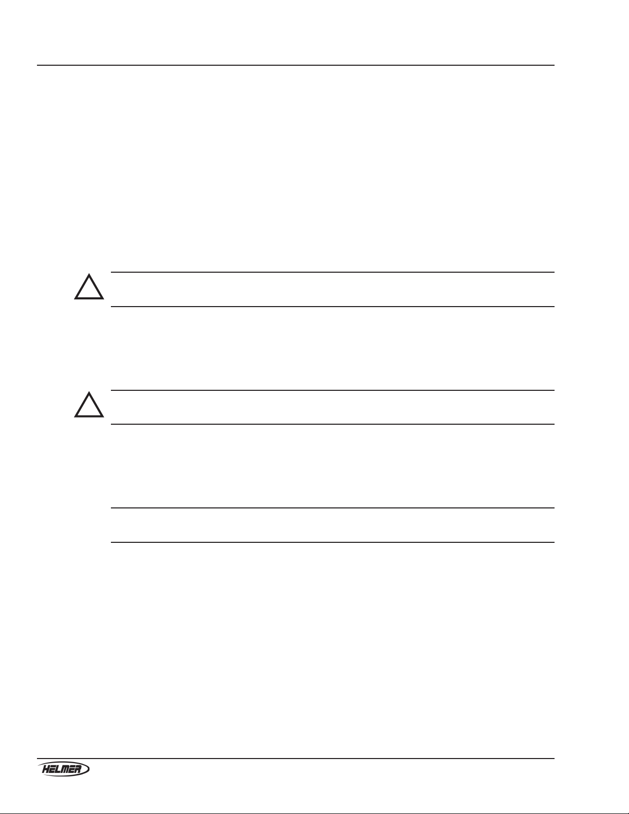
2.1 Touring the front, lid, and bowl
A
B
C
D
E
F
G
H
I
J
K
Left: Front of cell washer with lid open and rotor installed. Right top: Bowl with rotor removed.
Right bottom: Access hole
Label Description Function
A Lid handle Releases the lid lock and opens the lid
BLatch Latches the lid in the closed position
CSight window Provides visual access to the cell washer during
operation. Used for measuring rotor speed.
DNozzle Directs the saline wash solution into the rotor
ERotor Holds the tubes
FControl panel Controls and displays the status of the cell washer
G Drainage system Contains the liquid used during processing
HBowl Contains the liquid used during processing
I Drain Drains waste uid from the bowl
JRotor shaft Spins the rotor
K Access hole Provides access to the lid lock
4
360084-1/H
UltraCW™ Automatic Cell Washing System Operation Manual
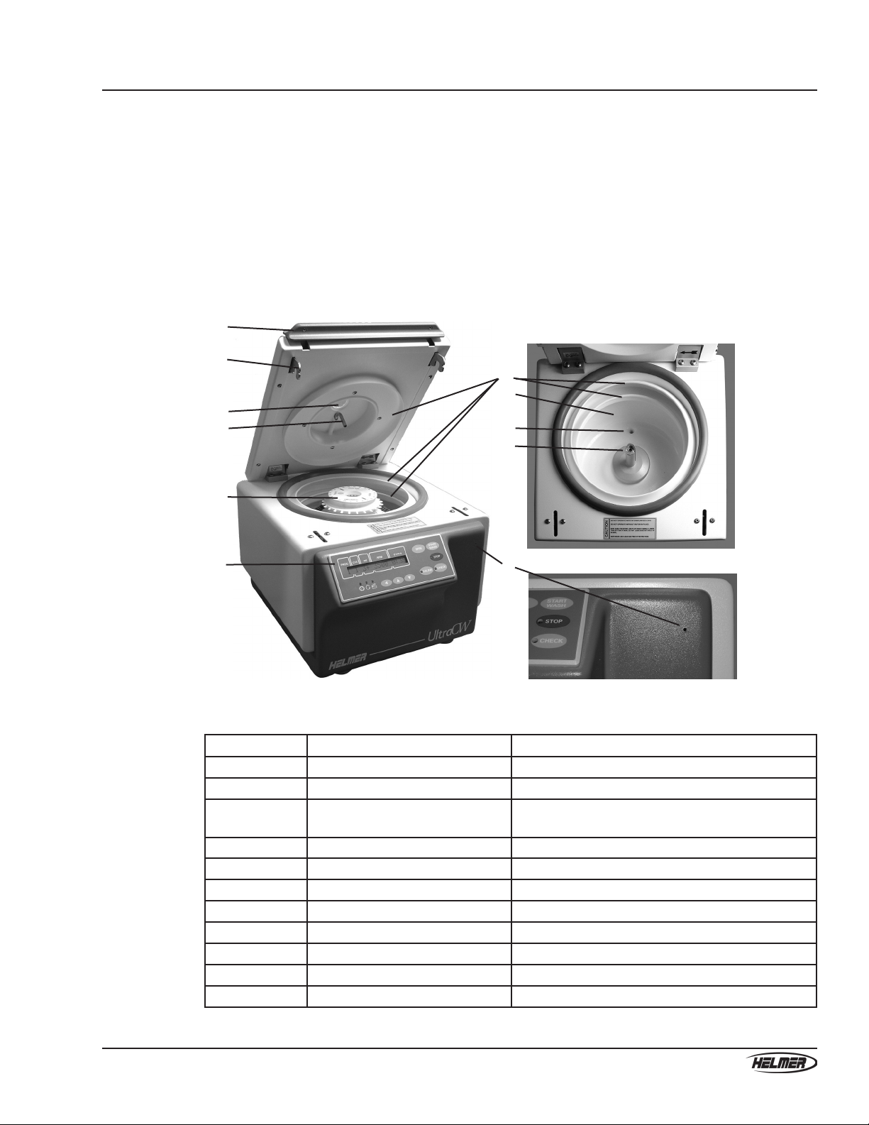
2.2 Touring the side
A B C D
View of right side of cell washer
Label Description Function
AFuse Prevents current overload
B Power switch Turns the cell washer on and off
CPower connector Interface for the power cord
DProduct Specication label Provides the model number, serial number, and
electrical requirements for the cell washer
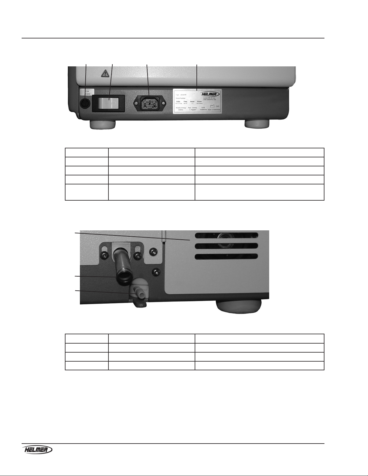
2.3 Touring the rear
A
B
C
View of rear of cell washer
Label Description Function
A Access door Provides access to the pump and pump tubing
BDrain connector Drains saline solution from the cell washer
C Supply connector Supplies saline solution to the cell washer
5
360084-1/H
Touring the cell washer
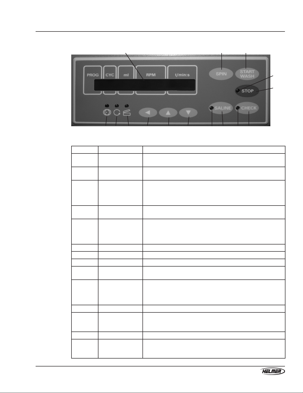
2.4 Touring the control panel
A B C
D
E
F G H I J K L M N O
Control panel (shown with cell washer turned off)
Label Description Function
A Message screen Displays process information, programming prompts, and error
messages
BSPIN button In display mode: Starts the process that uses the spinning group of
parameters of the selected program
CSTART WASH
button
In display mode: Starts the process that uses the washing group of
parameters of the selected program
In programming mode: Saves any changes being made to values in
the current parameter menu
D Stop lamp Indicates when the rotor is moving after a process has been paused or
stopped
E STOP button In processing mode: Stops the current process
In programming mode: Cancels any changes being made to values in
the current parameter menu
In calibration mode: Stops the ow of saline solution
FImbalance lamp Indicates when the rotor is not balanced
G Spin lamp Indicates when the rotor is moving
HLid Ready lamp Indicates when the lid is ready to be opened
I Parameter selection
button
In display mode: Enters programming mode
In programming mode: Selects a parameter
J, K Parameter value
buttons
In programming mode: Increases or decreases the value for
the selected parameter. Also toggles between the Shakings and
ShakeT(min) global parameters
In display mode: Selects a program
L Saline lamp Indicates when saline solution is being dispensed
M SALINE button In display mode: Enters calibration mode
In processing mode: Starts the Rell sequence of the cleaning
program
N Check lamp Indicates when a process has been paused
O CHECK button In processing mode: Pauses the process if it was started using the
START WASH button
In calibration mode: Starts the ow of saline solution
6
360084-1/H
UltraCW™ Automatic Cell Washing System Operation Manual
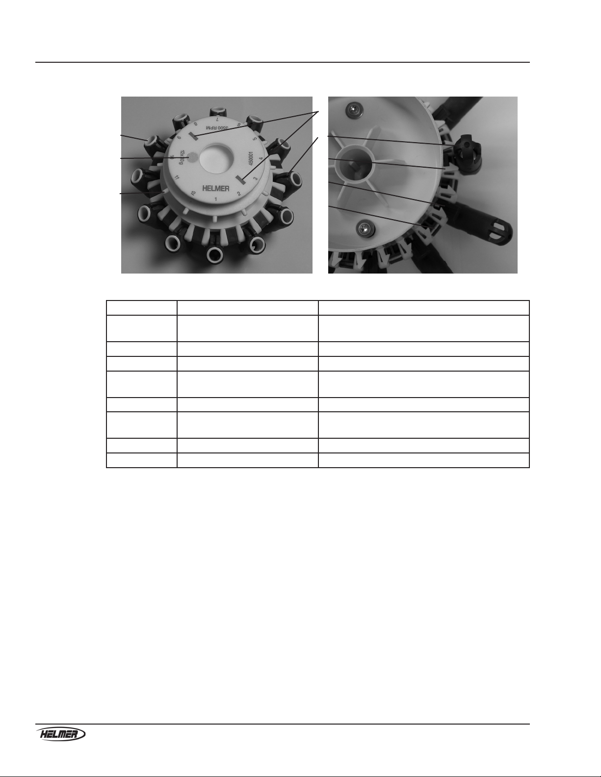
2.5 Touring the rotor
A
B
C
D
E
F
G
H
Left: Top view of 12-place rotor with inserts installed. Right: Bottom view of 12-place rotor
Label Description Function
A Tube holder insert Holds 10 mm x 75 mm tubes in the tube holders.
Removed when using 12 mm x 75 mm tubes
BOptical reference Provides a reference for testing the rotor speed
CFill port Directs saline solution into the tubes
D Alignment markings Provides a reference to align the rotor with the
rotor shaft
E Tube holder Holds the tube to be processed
F Rotor lock Holds the tube holder during the decant step of the
wash process
G Clip Secures the tube holder to the ring on the rotor
HRing Holds the tube holders on the rotor
7
360084-1/H
Installing the cell washer
3 Installing the cell washer
After you record identifying information and select an appropriate location for the cell washer, install the
cell washer.
3.1 Recordingidenticationinformation
For easy reference, write the serial number on the front of this manual. The serial number is needed to
provide efcient service.
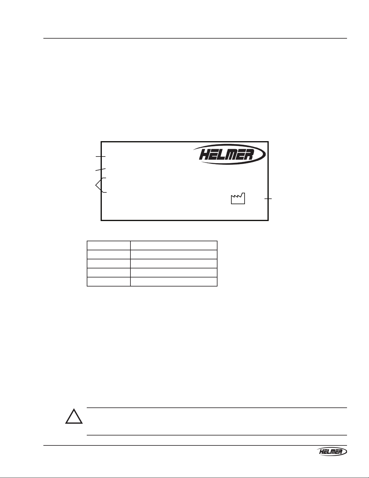
The Product Specication label is located on the right side of the cell washer next to the power connector.
A
B
C
D
Type: UltraCW
Serial Number 0000000
Volts Freq Amps Power
110-127Vac 60 Hz 2.5 200 Watts
Kinetic Energy Max. Density RPM
250Nm 1.2Kg/dm 3500R/min
3 Made in Switzerland
2006
www.helmerinc.com
Noblesville, IN USA
ProductSpecicationlabel(sample)
Label Description
AType (Model)
B Serial number (S/N)
CPower requirements
D Date of manufacturing
3.2 Selecting an appropriate location
To optimize cell washer operation, the location for your cell washer must meet the following requirements:
► A sturdy, level surface to provide support and proper drainage
► Has a minimum of 5 inches (12 cm) of space around all sides of the cell washer for ventilation
► Has a minimum of 13 inches (33 cm) of space above the cell washer for opening the lid
► Has access to a grounded outlet meeting the electrical requirements as listed on the Product
Specication label
► Has access to a saline supply
► Has access to a waste container or drain suitable to receive decanted saline and human blood waste
product. For proper drainage, keep the waste container below the cell washer and the drain line as short
as possible.
► Meets any additional requirements specied for your organization
!
WARNING: Some saline solution contains a sodium azide preservative which may react with
the drain plumbing to form dangerous explosive azide salts. Check with the saline
solution supplier before discharging waste solutions directly into normal drains.
8
360084-1/H
UltraCW™ Automatic Cell Washing System Operation Manual
3.3 Powering the cell washer
3.3.1 Installing the power cord
The power cord is included but packaged separately from the cell washer.
To install the power cord
► On the right side of the cell washer, connect the power cord to the connector.
3.3.2 Connecting to power
!
CAUTION: As with any electronic device, before connecting to power, make sure the cell
washer is at room temperature.
To connect to power
► Plug the power cord into a grounded outlet that meets the electrical requirements that appear on the
Product Specication label on the cell washer.
3.3.3 Turning the power on and off
The power switch is located on the right side of the cell washer.
To turn the power on
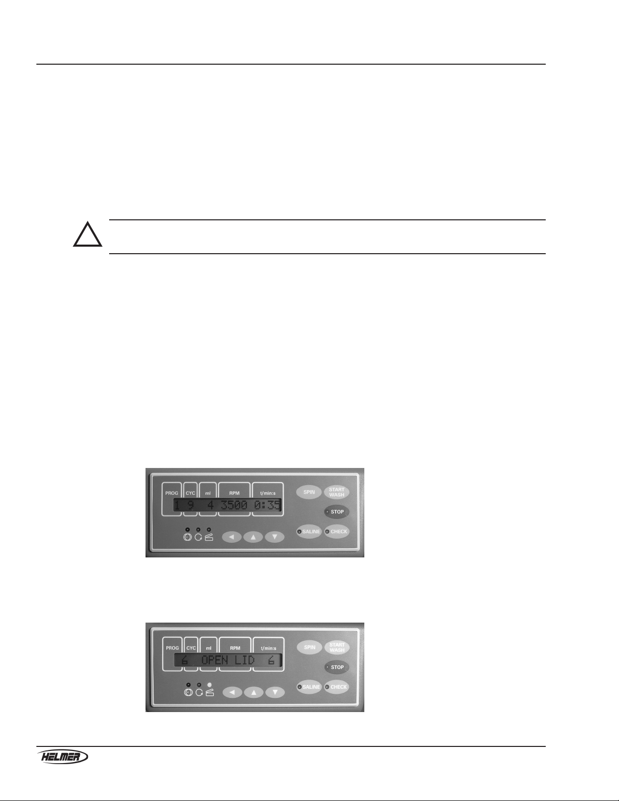
► Press the switch to the On ( │ ) position. The software version appears on the message screen and all
lamps are lit. After about eight seconds, the control panel changes to one of the following views:
► If the lid was open when the power was turned on, a summary of the washing parameters for the
selected program appears on the message screen and no lamps are lit.
Control panel after initialization when the lid was open.
► If the lid was closed when the power was turned on, OPEN LID appears on the message screen
and the Lid Ready lamp is lit.
Control panel after initialization when the lid was closed.

9
360084-1/H
Installing the cell washer
To turn the power off
► Press the switch to the Off ( ) position.
3.4 Opening and closing the lid
The cell washer is equipped with an electronically controlled lock that prevents the lid from being opened
during operation. The Lid Ready lamp must be lit for you to open the lid.
NOTE: If the lid is closed and there is no power to the cell washer, the lock prevents
the lid from being opened. If you must open the lid in this circumstance, or if
the lock is not working properly, see Section 7.4, “Releasing the lid lock” for
instructions to open the lid.
Left: Handle with latch in closed position. Right: Handle with latch in open position.
To open the lid
1 On the control panel, conrm that the Lid Ready lamp is lit.
2 Lift the handle to the open position to release the latch. The Lid Ready lamp clears.
3 Raise the lid.
To close the lid
!
CAUTION: To prevent damage to the cell washer and its contents, avoid dropping or
slamming the lid.
1 With the handle in the open position, close the lid.
2 Press down on the handle to move the latch to the closed position. OPEN LID appears on the message
screen and the Lid Ready lamp lights.
3.5 Removing packaging materials
Before using the cell washer, open the lid and remove all packaging materials from the rotor and bowl.
NOTE: Keep the packaging materials for future use.
10
360084-1/H
UltraCW™ Automatic Cell Washing System Operation Manual
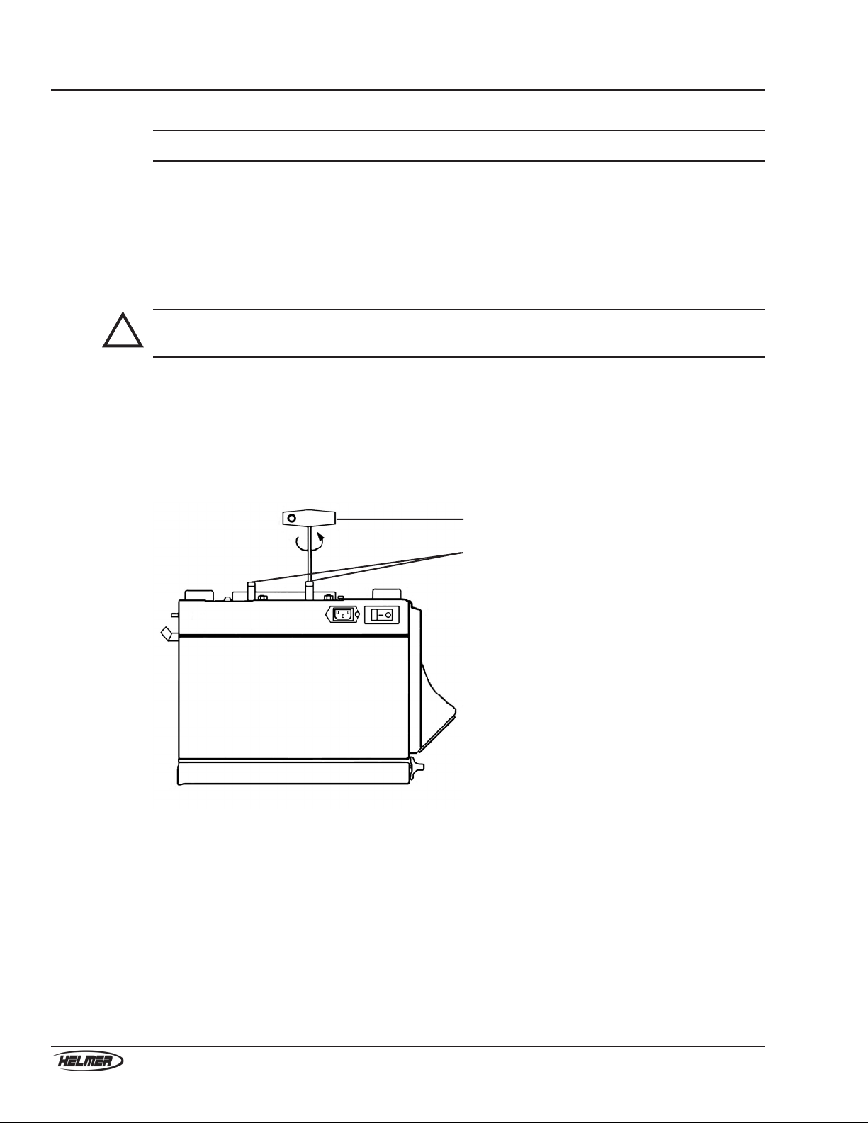
3.6 Removing the transport bolts
NOTE: Keep the transport bolts and removal tool for future use.
The transport bolts are located on the bottom of the cell washer. They keep the motor from moving during
transport, and must be removed prior to use.
You will need the transport bolt removal tool to perform this procedure. The tool is included but packaged
separately from the cell washer.
To remove the transport bolts
!
CAUTION: To avoid damaging parts, do not tip the cell washer on its back or side while
removing the transport bolts.
1 With the power to the cell washer on, open the lid and remove the rotor. For more information and
instructions, see Section 5.1.1, “Installing and removing the rotor.”
2 Close the lid and place the cell washer upside down so that the bottom faces upward.
3 On the bottom of the cell washer, locate the two transport bolts.
4 Use the bolt removal tool to remove the bolts.
5 Return the cell washer to the upright position.
A
B
View of right side of cell washer. A: Transport bolt removal tool. B: Transport bolts.

11
360084-1/H
Installing the cell washer
3.7 Connecting to the saline supply and drain
After installing the supply and drain tubing, connect to the saline supply and drain.
3.7.1 Installing and removing the supply and drain tubing
Tubing is used to connect to the saline supply and to the drain. The tubing is included but packaged
separately from the cell washer. The smaller-diameter tubing is for the saline supply. The larger-diameter
tubing is for the drain.
The supply and drain tubing should be replaced on a regular basis to prevent unexpected failure. The
tubing may need to be replaced more frequently depending on how frequently the cell washer is used
and policies for your organization. You will need the Drain/Fill Tubing Assembly to replace the tubing.
This kit is available for purchase from Helmer. For the recommended replacement schedule, see Section
6.1, “Reviewing the preventive maintenance schedule.” For replacement part numbers, see Section 8.1.7
“Supplies.”
To install the saline supply tubing
► On the rear of the cell washer, on the supply connector, rmly press the smaller-diameter tubing around
the connector until the tubing covers the barb. Twisting the tubing while pressing it onto the connector
facilitates installation.
To install the drain tubing
► On the rear of the cell washer, on the drain connector, rmly press the larger-diameter tubing around
the connector until the tubing covers the barb. Twisting the tubing while pressing it onto the connector
facilitates installation.
To remove supply or drain tubing
!
CAUTION: If the vacuum is not released, the connector could break off, requiring part
replacement.
► While twisting to release the vacuum, pull the tubing off the connector.

12
360084-1/H
UltraCW™ Automatic Cell Washing System Operation Manual
3.7.2 Connecting to the saline supply
If the connector or tubing on your saline supply is larger than that for the cell washer, you can use an
adapter. The adapter is included but packaged separately from the cell washer.
To connect the adapter
1 Connect the smaller end of the adapter to the end of the supply tubing.
2 Connect the larger end of the adapter to the connector on the saline supply.
3.7.3 Connecting to the drain
The cell washer has a gravity drain. Ensure that the drain tubing ows downward, is as short as possible,
and is not restricted in any way.
!
WARNING: Some saline solution contains a sodium azide preservative which may react with
the drain plumbing to form dangerous explosive azide salts. Check with the
saline solution supplier before discharging waste solutions directly into normal
drains.
!
CAUTION: If the drain line becomes kinked or restricted, drained liquid can accumulate
in the bowl and enter the tubes during the wash process, yielding unacceptable
results. Excessive liquid in the bowl may also enter the motor compartment,
causing motor failure.

13
360084-1/H
Programming the cell washer
4 Programming the cell washer
When you program the cell washer, you are dening a process which will later be automatically executed
when you start the program. You control the steps of the process by setting parameters, which are viewed
and changed from two menus: the Global menu and the Program menu.
This section describes the major types of processes, the steps that make up those processes, and the
parameters used to control the steps. Once you are familiar with the concepts, you will be ready to plan
programs for your processes, then program the cell washer to execute them at the touch of a button. For
sample programs, see Section 8.2, “Sample programs.”
4.1 Understanding processes and process steps
The cell washer is capable of executing ve major types of processes. Each process consists of one or more
process steps.
4.1.1 Understanding processes
The major types of processes are as follows:
Washing processes. Washing processes include at least one basic wash cycle, which is composed of three
steps: Fill, Spin, and Decant. Washing processes may also include one or more of the following steps:
Agitation, Drop spin-down, Suspension, and Suspension-agitation.
Suspension processes. Suspension processes include one Suspension step, but exclude Fill, Spin, and
Decant steps. Suspension processes may also include a Suspension-agitation step after the Suspension step.
Spinning processes. Spinning processes include one Spin step, but exclude a Fill step. Some Spinning
processes may also include one or more of the following steps: Agitation and Decant.
Agitation processes. Agitation processes include one Agitation step, but no other steps.
Cleaning process. The cleaning process is a preset sequence that requires user intervention. After the user
prepares the system for cleaning, the following steps are executed: Fill, Spin, Decant, Agitation, Decant.
The user must then prepare the system for normal operation, then start a Rell sequence to complete the
process.
4.1.2 Understanding process steps
Each process consists of one or more process steps. Each process step is controlled by setting a combination
of global and program parameters. For more information about global and program parameters, see Section
4.2, “Understanding programs and parameters.”
4.1.2.1 Understanding the Fill step
During the Fill step, the tubes containing cells are lled with a specied amount of saline solution. As
the rotor spins at 1100 r/min, saline is pumped from the reservoir through the ow meter to the saline
dispensing nozzle. The nozzle directs the saline into the rotor, then the ll ports direct the saline into the
tubes. Saline enters the tubes in a direct stream to maximize cell re-suspension.
For washing processes, this step is always executed rst in the basic wash cycle (Fill, Spin, Decant). You
specify the amount of saline solution with the SalWash/ml program parameter. For sample processes that
include this step, see Section 8.2.1, “Sample single-cycle washing process” and Section 8.2.2, “Sample
multiple-cycle washing process.”

14
360084-1/H
UltraCW™ Automatic Cell Washing System Operation Manual
For the cleaning process, this step is always executed rst. The amount is preset at 10 ml per place on the
rotor. The ll volume exceeds the capacity of the tube to aid in ushing the drainage system.
4.1.2.2 Understanding the Spin step
During the Spin step, the rotor accelerates to the specied speed, spins for the specied time, then stops
quickly. This step separates out unwanted particles and creates a button of red blood cells at the bottom of
each tube. The quick stopping action prevents the re-suspension of the red blood cells and dislodging of the
cell button.
For washing processes, this step is always executed second in the basic wash cycle (Fill, Spin, Decant).
You specify the speed with the Wash(rpm) parameter, and the duration with the Twash(min) and Twash(sec)
parameters. For sample processes that include this step, see Section 8.2.1, “Sample single-cycle washing
process” and Section 8.2.2, “Sample multiple-cycle washing process.”
For spinning processes, this step is always executed either rst, or immediately after the optional Agitation
step. You specify the speed with the Spin(rpm) parameter, and the duration with the Tspin(min) and
Tspin(sec) parameters. For sample processes that include this step, see Section 8.2.5, “Sample spinning-
only process,” Section 8.2.6, “Sample spinning with decanting process,” and Section 8.2.7, “Sample
spinning after agitation process.”
For the cleaning process, this step is always executed after the Fill step. The speed is preset at 1500 r/min,
and the duration is preset at 10 seconds.
4.1.2.3 Understanding the Decant step
During the Decant step, the rotor rapidly accelerates to the specied speed and decelerates, allowing the
tubes to move back to the neutral position so the rotor lock can engage properly. The rotor spins in the
opposite direction at the specied speed, while the rotor lock holds the tubes at a slight negative angle.
Waste solution is expelled from the tubes by low centrifugal force, while virtually all the cells are retained
in the tubes in the form of cell buttons. The waste solution is directed to the drain hole in the bowl by the
drainage system. From there, the spent solution ows out of the cell washer into the drain tubing to the
waste container or drain.
For washing processes, this step is always executed third in the basic wash cycle (Fill, Spin, Decant). You
specify the speed with the Decant(rpm) global parameter. For sample processes that include this step, see
Section 8.2.1, “Sample single-cycle washing process” and Section 8.2.2, “Sample multiple-cycle washing
process.”
For spinning processes, this step is optional. For this step to be executed, both the SpinDecantM. global
parameter and the SpinDecant program parameter must be enabled. This step is executed after the Spin
step. You specify the speed with the Decant(rpm) global parameter. For a sample process that includes this
step, see Section 8.2.6, “Sample spinning with decanting process.”
For the cleaning process, this step is executed twice: once after the Spin step, then again after the Agitation
step. The speed is preset at 600 r/min.

15
360084-1/H
Programming the cell washer
4.1.2.4 Understanding the Drop spin-down step
During the Drop spin-down step, the rotor spins at 2000 r/min for the specied time. This action forces
drops that are clinging to the sides of the tubes to the bottom of the tubes, thereby increasing the sample
yield.
This step is optional and available only for washing processes. For this step to be executed, both the
DSpinDown(s) global parameter and the DSpinDown program parameter must be enabled. This step is
executed after the Decant step. You specify the time with the DSpinDown(s) global parameter. For a sample
process that includes this step, see Section 8.2.1, “Sample single-cycle washing process.”
4.1.2.5 Understanding the Agitation step
During the Agitation step, the rotor accelerates to 200 r/min then stops, frequently and briey, disrupting
(breaking apart) the cell buttons.
You must specify either the number of agitation cycles per agitation step with the Shakings global
parameter, or the duration of each agitation step with the ShakeT(min) global parameter.
For washing processes that consist of one basic wash cycle (Fill, Spin, Decant), this step is not executed.
For washing processes that have multiple basic wash cycles, this step is executed between each basic wash
cycle. You must specify either the number of agitation cycles per agitation step with the Shakings global
parameter, or the duration of each agitation step with the ShakeT(min) global parameter. For a sample
process that includes this step, see Section 8.2.2, “Sample multiple-cycle washing process.”
For spinning processes, this step is optional. For this step to be executed, both the AgitSpinM. global
parameter and the Agit.Spin program parameter must be enabled. This step is executed before the Spin
step. You must specify either the number of agitation cycles per agitation step with the Shakings global
parameter, or the duration of each agitation step with the ShakeT(min) global parameter. For a sample
process that includes this step, see Section 8.2.7, “Sample spinning after agitation process.”
For agitation processes, this step must be executed. You must set a series of global and program parameters
to certain values depending on how you intend to start the process. For sample agitation-only processes, see
Section 8.2.8, “Sample agitation-only processes.”
For the cleaning process, this step is always executed between the Decant steps. The number of agitation
cycles is preset at 5 cycles.
4.1.2.6 Understanding the Suspension step
The Suspension step works the same as the Fill step, but is executed differently.
For this step to be executed, both the SuspensionM. global parameter and the SalSusp/ml program
parameter must be enabled. You specify the amount of saline that is dispensed with the SalSusp/ml program
parameter.
For washing processes, this step is optional. If enabled, this step is executed after the nal Decant step,
preceded by the optional Drop spin-down step. For a sample process that includes this step, see Section
8.2.1, “Sample single-cycle washing process.”
For suspension processes, this step must be executed. This step is either the rst or the only step. For
sample processes that include this step, see Section 8.2.3, “Sample suspension-only process” and Section
8.2.4, “Sample suspension with agitation process.”
Other manuals for UltraCW
1
Table of contents
Other Helmer Washer manuals


 user manual")


