Henco UFH-PGKTA User manual

SnelSelectie kaart
Henco UFH-PGKTA
en
HENCO Industries NV • Toekomstlaan 27 - B-2200 Herentals • Tel. +32 14 28 56 60 • Fax +32 14 21 87 12 • www.henco.be
IMPORTANT!
Before starting work the fitter must carefully read this installation and opera-
tion manual, understand and observe its conditions.
The water floor heating control unit may be mounted, operated and main-
tained only by specially trained personnel. Personnel undergoing training
may only work on the product under the supervision of an experienced fitter.
Only when the above conditions are fulfilled, the manufacture is responsible
for the equipment as provided in the legal regulations.
All instructions in this assembly and operation manual must be observed
when working with the water floor heating control unit. Any other application
is not in compliance with the regulations. The manufacturer shall not be responsible for incompetent use of the
water floor heating control unit. Reconstructions and changes are not acceptable for reasons of safety. The water
floor heating control unit may be repaired only by services approved by the manufacturer.
The temperature range and the contents of the set depend on the model and equipment.
Subject to technical modification!
1. RANGE OF APPLICATION 1
2. DETAILS, SYMBOLS AN 2SNOITAIVERBBAD
3. SAFETY INSTRUCTIONS 4
4. DESIGN 4
5. INSTALLATION AND ELEC 4NOITCENNOCLACIRT
5.1. MOUNTING OF THE CONTROL UNIT 4
5.2. ELECTRICAL CONNECTION6
5.3. TEMPERATURE LIMITER (TB)6
6. START-UP 6
6.1. FLUSHING THE HEATING CIRCUITS 6
6.2. ADJUSTMENT OF THE FLOOR HEATING FLOW TEMPERATURE7
6.3. LIMITATION OF THE FLOOR HEATING FLOW TEMPERATURE 7
7. 7TINULORTNOCEHTFONOITAREPOFOEDOM
8. 7SLAIRETAM/ATADLACINHCET
9. TROUBLESHOOTING 8
1. RANGE OF APPLICATION
The control unit UFH-PGKTA is developed for maintaining constant flow temperature in low-temperature radi-
ant heating systems. The flow temperature may be adjusted gradually between 20 and 70 °С, by means of the
thermostat. The limitation of the adjustment range is possible according to the maximum/minimum tempera-
ture. The temperature value can be read from the thermometer of the control unit.
The control unit is suitable for use in installations with combined panel heating/cooling and radiator heating. In
cooling operation the thermostatic head fully opens the 3-way-mixing valve and at the same time closes the
bypass. Thereby the flow temperature shall be controlled by the chiller (e.g. combined heat pump heat-
ing/cooling).
The control unit can be mounted either to the right or left of heating circuit manifolds with 1" male thread and
distance between supply and return branch of 210 mm. For that it is equipped with union nuts G 1".
The control unit has been designed for use in dry environments, e.g. in residential rooms, office spaces, and
industrial facilities. Usually the unit is installed in the central heating room or in a manifold cabinet.
Verify that the installation complies with existing regulations before operation to ensure proper use of the in-
stallation.
Fi
g
.1
en
HENCO Industries NV • Toekomstlaan 27 - B-2200 Herentals • Tel. +32 14 28 56 60 • Fax +32 14 21 87 12 • www.henco.be
2. DETAILS, SYMBOLS AND ABBREVIATIONS
For better understanding in this document references are used in the form of symbols and abbreviations, which are
described below:
Reference to resuming documents.
Important information and application hints
Safety instructions or important note to the function.
Shut-off: no flow
Open: flow with indication of flow direction
AG male thread
EUKOmale thread with euro cone
FBH floor heating
FH radiant heating (generally)
FH/K radiant heating/cooling
FK radiant cooling
FRG floor heating control unit
HK heating control unit
HKM heating control unit with mixing valve
HKV manifold
IG female thread
MuB installation leaflet
RV check valve
KFE fill and drain cock
SKB gravity flow stop
TB temperature limiter
UM union nut
UWPcirculation pump
WDS heating insulation box
WE boiler / heat generator
WP heat pump
3. SAFETY INSTRUCTIONS
WARNING: Always disconnect the power supply prior to performing any installation or connec-
tion operations!
All installation and wiring work at the unit must be carried out only in an idle condition.
The appliance may be connected and put to operation by qualified personnel only. Make sure to adhere
to valid safety regulations, in particular to VDE 0100 (German standard governing power installations
with nominal voltages ≤1000 VAC).
The control units are neither splash- nor drip-proof. Therefore, they must be mounted in a dry place.
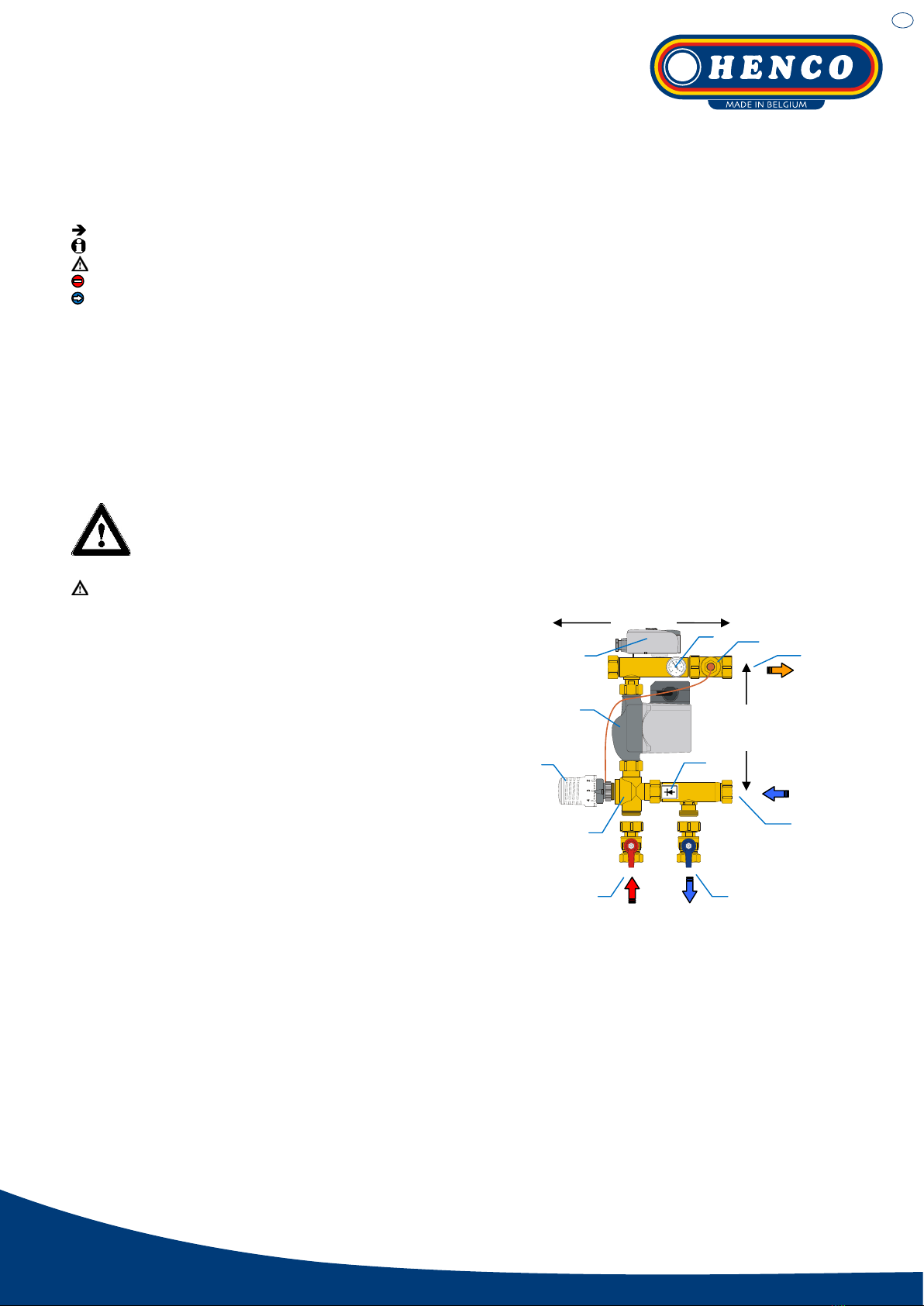
4. DESIGN
1: Floor heating/cooling supply (1“ UM)
2: Floor heating/cooling return (1“ UM)
3: Primary supply (1“ AG)
4: Primary return (1“ AG)
5: Circulation pump
6: Thermostatic head
7: 3-way-mixing valve
8: Check valve (RV)
9: Supply temperature thermometer
10: Temperature limiter (optional)
11: Z-type fitting with immersion sleeve for supply temperature sensor.
5. INSTALLATIONANDELECTRICAL CONNECTION
5.1. MOUNTING OF THE CONTROL UNIT
The unit is dedicated for flat sealing connecting to a manifold with 1” male thread and distance between supply and
return branch of 210 mm.
Please pay attention not to damage or break the cables of the pump and temperature limiter as well as the capillary
pipe of the thermostatic heads remote sensor while assembling. The cables must be installed without tension.
The correct installation of supply and return has to be ensured (Fig.2 and Fig.3.1 – 3.4).
Fig.2
1
2
210 mm
3 4
5
6
7
9
10
11
ca. 270 mm
8

en
HENCO Industries NV • Toekomstlaan 27 - B-2200 Herentals • Tel. +32 14 28 56 60 • Fax +32 14 21 87 12 • www.henco.be
6
10 14
15
TK
7
11
9
12
13 9
>T°C
230 V
Installation diagram floor heating/cooling
Reversible heat pump (for heating and cooling)
18
UFH-PGKTA
Fig.3.4
8
6
10 14
15
TK
7
11
12
13
>T°C
230 V
Installation diagram floor heating/cooling
Separated boiler and chiller
17
M
1 16
UFH-PGKTA
Fig.3.3
8
9
9
6
10 14
15
5
TK
7
11
9
12
13
2
34
9
>T°C
230 V
Installation diagram radiator and floor heating
Common ascending pipe
19
1
UFH-PGKTA
Fig.3.2
8
6
10 14
15
5
TK
7
11
9
12
13
2
34
9
>T°C
230 V
Installation diagram radiator and floor heating
Separated ascending pipes
19
1
UFH-PGKTA
Fig.3.1
8
Fig.4
L
N
PE
UW
P
L
PE
N
PEC 2 1
TB
WTC-ES / WTC-IS
1 Boiler
2 Circulation pump boiler / radiator circuit
3 Boiler / Radiator supply
4 Boiler / radiator return
5 Radiator
6 FH/K supply
7 FH/K return
8 Manifold (HKV)
9 Fill and drain cocks (KFE)
10 3-way-mixing valve with thermostatic head
11 Circulation pump for FH/K
12 Temperature limiter (option)
13 Remote sensor of thermostatic head
14 Check valve
15 Shut-off valves (recommendable)
16 Chiller
17 Zone valve
18 Reversible heat pump (heating and cooling)
19 Hydraulic switch
en
HENCO Industries NV • Toekomstlaan 27 - B-2200 Herentals • Tel. +32 14 28 56 60 • Fax +32 14 21 87 12 • www.henco.be
5.2. ELECTRICAL CONNECTION
All electrical connections must be performed by an authorised specialist in accordance with the local regulations
governing electrical installation work. The electrical cables must not come into contact with any hot parts.
Both the circulation pump and the temperature limiter are connected with cables ex-works (see Fig.4). The power
supply has to be established on site.
In order to make sure that the pump only runs if heat requirement exists, the manufacturer recommends connecting
it to a pump relay (e.g. pump logic of an electrical connection box which controls the actuators). Alternatively operate
the pump by means of a timer.
Further information about electrical connections exists in the MuB of the pump and temperature limiter
5.3. TEMPERATURE LIMITER (TB)
In the event of malfunction, the TB switches off the circulating pump to prevent overheating of the floor heating sys-
tem. To avoid undesired activation, the temperature on the TB should be set several degrees above the desired flow
temperature. In practice the usual maximum temperature value is approx. 55 °C. That corresponds to the factory
setting of the TB. If necessary this maximum temperature must be adapted to the local conditions.
If all floor heating circuits are equipped with actuators and no pump relay is used, the TB should be installed on the
supply branch of the manifold.
6. START-UP
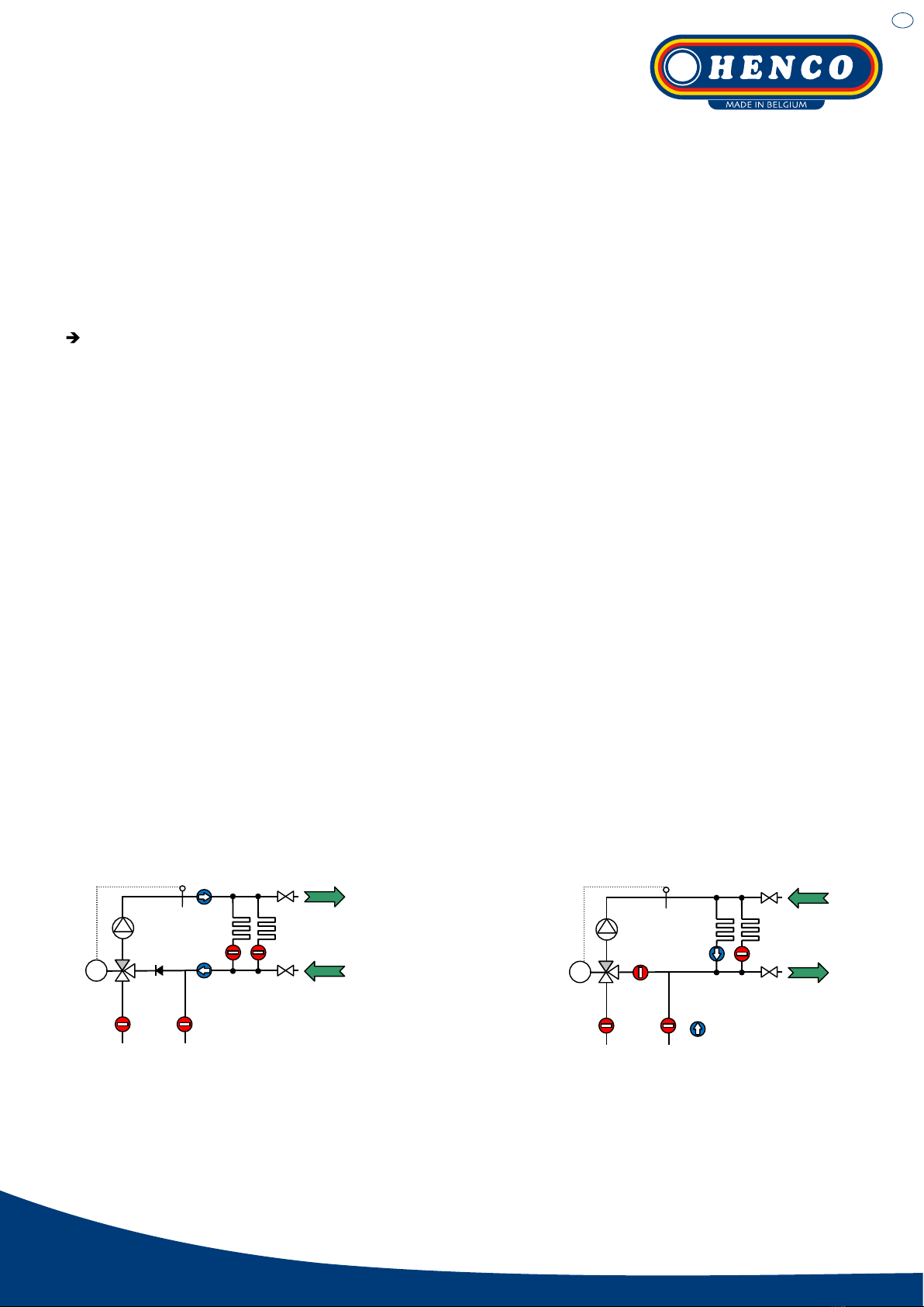
6.1. FLUSHING THE HEATING CIRCUITS
Connect the control unit to the heating system. Shut off from the boiler circuit (using the ball valves (15) supplied with
the manifold or via a shut-off device mounted on site). Switch off the pump and close all heating circuits at the mani-
fold. It is sufficient to close only the valves in the return collector of the HKV using the protective caps.
Fill the manifold and the FRG with heating water in accordance to VDI2035 first. Connect the fill hose to the KFE
cock mounted on the manifold return branch (Fig.5_9b) and the discharge hose to the KFE cock on the manifold
supply branch (Fig.5_9a). Heating circuits shall be closed. Open the KFE cocks until water discharges on the KFE
cock in the supply. Close both of the cocks.
To fill and rinse the heating circuits connect the fill hose to the KFE cock on the supply branch of the manifold
(Fig.6_9a) and the drain hose to the KFE cock on the return branch of the manifold (Fig.6_9b). Open the circuit to be
filled and rinsed. Afterwards open the KFE cock and flush the loop until air and any impurities are completely re-
moved from the circuit. The check valve (14) in the bypass of the 3-way-mixing valve prevents a short-circuit when
rinsing the heating loops.
Repeat that procedure for all heating circuits.
Important: It should be rinsed only in the flow direction, i. e. the rinsing water has to enter at the KFE cock on the
supply branch of the manifold and discharging via KFE cock on the return branch of the manifold!
The drain/discharge connection must always be open; otherwise the high water pressure could damage the heating
system. Also read the instructions on flushing as outlined in the installation/operating instructions for the heating
circuit manifold.
Fig.5
10 14
15
TK
9a
9b
Fig.6
10 14
15
TK
9a
9b
en
HENCO Industries NV • Toekomstlaan 27 - B-2200 Herentals • Tel. +32 14 28 56 60 • Fax +32 14 21 87 12 • www.henco.be
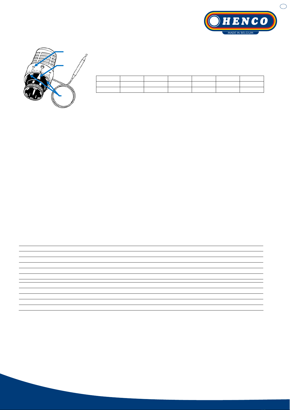
6.2. ADJUSTMENT OF THE FLOOR HEATING FLOW TEMPERATURE
The flow temperature may be adjusted gradually between 20 to 70 °C (68 to 158
°F). The regulating hand wheel of the thermostat is supplied with a scale 1-7
(Fig.7_A). Please see the temperatures set on the scale in the table below:
1 2 3 4 5 6 7
20 °C 28 °C 37 °C 45 °C 53 °C 62 °C 70 °C
68 °F 82.4 °F 98.6 °F 113 °F 127.4 °F 143.6 °F 158 °F
6.3. LIMITATION OF THE FLOOR HEATING FLOW TEMPERATURE
As a rule, the flow temperature in floor heating systems should not be higher
than 50 °C (120 °F). However, the data of the floor heating system can deviate and should be considered. The flow
temperature of the system is often lower than the adjustable maximum value of the thermostat. To avoid damages in
the floor structure caused by excess temperature, the flow temperature set value may be defined and limited on the
thermostatic head.
Therefore, it is most important to set the determined value and check it by means of thermometer during operation of
the floor heating system. If it is correct, place the blocking elements (Fig.7_B) right before and behind the pointer
(Fig.7_C).
Furthermore the temperature set value can be protected against inadvertent manipulation using the tamper-proof
cover.
7. MODE OF OPERATION OF THE CONTROL UNIT
The mixing valve is designed as a proportional controller and operates without auxiliary energy. The thermostat situ-
ated in the supply is in continuous contact with the flow temperature at all times.
Deviations from the target value result in an immediate change in valve stroke and, accordingly, a change in the
volume of the hot water injected from the boiler circuit.
The injected water volume is mixed with the return water from the manifold at the inlet to the circulation pump and, in
this way, keeps the flow temperature constant within a narrow temperature range.
8. TECHNICAL DATA / MATERIALS
Admissible ambient temperature range: 0…40 °C (32…104 °F) 1)
Admissible operating flow temperature range: 0…80 °C (32…176 °F) 1)
Maximum operating pressure: 6 bar (87 psi)
Flow temperature setting range: 20…70 °C (68…158 °F)
Wk41.xorppa:tuptuotaehdetaR 2)
zH05–CAV032:ylppusrewoP
85sMssarB:sgnittiF
leetssselniatsro36sMssarB:sepiP
tnatsisererutarepmetdna-tcapmI:citsalP
MDPEro43MFA:steksaG
MDPE:sgniR-O
1) Please refer also to technical leaflets of the pump
2) The temperature set value can be protected against inadvertent manipulation using the tamper-proof cover
C
A
B
Fig.7

en
HENCO Industries NV • Toekomstlaan 27 - B-2200 Herentals • Tel. +32 14 28 56 60 • Fax +32 14 21 87 12 • www.henco.be
9. TROUBLESHOOTING
X. PROBLEM
X.XnoituloSesuacelbissoP
1. THE HEATING CIRCUITS OF THE FLOOR HEATING (FH) ARE NOT HEATED UP
1.1 The temperature limiter (TB) switches off the circulating pump of the
control unit.
Cause: TB is set to a very low value.
Set the TB by approx. 10 K higher than the required flow tempera-
ture for FH.
Take into consideration the max. admissible flow temperature!
Differential gap of the TB: approx. 6 K.
The unit restarts quicker if the TB is removed from the unit for a
short time to allow a faster cooling down to switch-on temperature.
1.2 The TB switches off the circulating pump of the control unit.
Cause: Initially, the circulating pump remains switched on even
when all of the floor heating circuits are blocked. The “idle running”
of the pump without water circulation heats up the water due to
waste heat of the pump motor. On reaching the maximum tempera-
ture, the TB switches off the circulating pump!
Remove the TB from the compact control unit and install it at the
supply line or, eventually, at the return line of the heating circuit
manifold.
Use an electrical connecting box with pump relay (pump logic).
Thanks to the relay, the circulating pump operates only if at least
one heating circuit of FH is opened (requires heat).
1.3 The circulating pump is connected to a room-temperature thermostat
or to an electrical connecting box.
If all the actuators close, the pump is switched off. If the idle period is
longer, the supply water for FH is cooled down. Therefore, the injec-
tion mixing valve opens and hot water is injected from the primary
circuit. As a result, the control unit is heated up. On reaching the
TB’s switch-off temperature, the contact opens. The pump will not
switch on again.
Remove the TB from the compact control unit and install it at the
supply line or, eventually, at the return line of the heating circuit
manifold.
Subsection 1.1 should also be taken into consideration.
2. THE SUPPLY WATER TEMPERATURE CANNOT BE SET TO THE REQUIRED VALUE OR IT FLUCTUATES WITHIN A VERY WIDE
RANGE
2.1 The compact control unit’s supply (inlet) pipe and return (outlet) pipe
are misconnected.
Check all inlets and outlets of the compact control unit for correct
connection. Supply inlets and return outlets are marked with stickers.
Please take into account Fig. 2 and 3.
2.2 The circulating pump’s pressure head/pump stage is set at a very
high value.
Increase the rotation frequency, the pump’s pressure head/pump
stage, respectively.
2.3 The heating load is too big for the control unit used, i.e., the heat
consumption exceeds the rated heat output of the compact control
unit. This state may set in temporarily, e.g., in case of heating a
“cold” floor for the first time.
Check the maximum heat consumption and compare it with the rated
heat output. If necessary, distribute the heating circuits to a second
control unit with a respective manifold.
If the cause is in the initial heating up of a given floor heating sys-
tem, the function may be normalized after the heating up phase. This
is possible chiefly in an operating mode within the top values of the
rated power.
2.4 RevitcefedsidaehcitatsomrehT eplacement of thermostatic head.
Table of contents
Other Henco Control Unit manuals


