Quick Installation Guide
The descriptions and photographs
contained in this document are supplied
by way of example and illustration only.
Henco Industries reserves the right
to carry out any technical and design
improvements to its products without
prior notice. Henco hereby objects to
any term, dierent from or additional
to Henco terms, contained in any buyer
communication in any form, unless
agreed to in a writing signed by an ocer
of Henco.
2012/19/EU: Products marked with
this symbol cannot be disposed of
as unsorted municipal waste in the
European Union. For proper recycling,
return this product to your local supplier
upon the purchase of equivalent new
equipment, or dispose of it at designated
collection points. For more information
see:
https://www.henco.be
/en/henco-logic
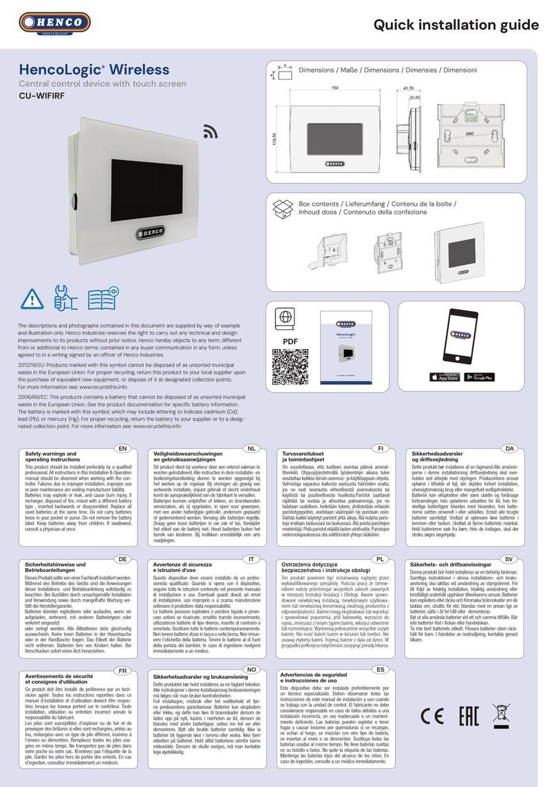
HENCOLOGIC
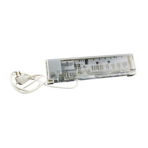
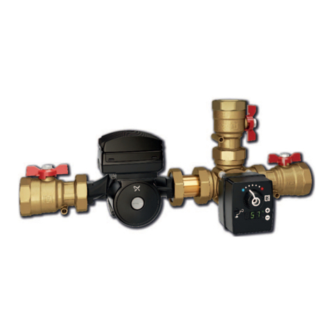
EXTENSION MODULE 6 ZONES + CONTROL UNIT H/C
6+6 zones, Heating & Cooling, Wired - CU-6ZONEB-HC + CU-6ZONE-CON
1
23
EN
Safety warnings and operating instructions
This product should be installed preferably by a qualied
professional. All instructions in this Installation & Operation
manual should be observed when working with the
controller. Failures due to improper installation, improper
use or poor maintenance are voiding manufacturer liability.
FR
Avertissements de sécurité et consignes d‘utilisation
Ce produit doit être installé de préférence par un technicien
agréé. Toutes les instructions reportées dans ce manuel
d‘installation et d‘utilisation doivent être respectées lorsque
les travaux portent sur le contrôleur. Toute installation,
utilisation ou entretien incorrect annule la responsabilité du
fabricant
NL
Veiligheidswaarschuwingen en
gebruiksaanwijzingen
Dit product dient bij voorkeur door een erkend vakman te
worden geïnstalleerd. Alle instructies in deze installatie- en
bedieningshandleiding dienen te worden opgevolgd bij het
werken op de regelaar. Bij storingen als gevolg van verkeerde
installatie, onjuist gebruik of slecht onderhoud komt de
aansprakelijkheid van de fabrikant te vervallen.
DIP switch number Function Value (default : OFF) Conguration
1 Controller function OFF Controller
ON Sub Controller
2 Pump
(available only on main controller, the
sub is always local)
OFF Local pump
ON Global pump
3 Pump start delay OFF 2min
ON 5min
4 H&C order OFF External H&C input
ON Master Thermostat
5 Time before H&C switch OFF No delay
ON 5 minutes delay
6 H&C outputs OFF Demand on any zone
ON Mode
OFF= Zone1/Zone2
ON=Zone1+Zone2
1 LED/zone
Demand= RED
= Red
= Blue
Overheating = Blinking RED
Green
Green
OFF= Zone3/Zone4
ON=Zone3+Zone4
OFF= Zone7/Zone8
ON=Zone7+Zone8
OFF= Zone9/Zone10
ON=Zone9+Zone10
