Somati system FSTronic IRC-FI User manual

Control unit FSTronic IRC-FI
Designed for drives of sliding (or vertically moving
with counter weight) fire gates with system of battery
backup
Content:
1. Power supply .......................................................... 2
2. Configuration .......................................................... 2
3. Installation and setting............................................. 4
4. Connection of other external devices....................... 11
5. Description of control and terminal blocks................ 13
6. Counter of cycles on control panel .......................... 24
7. Value report on the functional display...................... 25
8. Errors on frequency invertor................................... 27
9. Connectors............................................................ 28
10. Control panel ........................................................ 30
11. Regular service...................................................... 32
12. Circuit diagrams .................................................... 34
manual for version: IRC-FI v 1_0
version
STANDARD
Vrersion
COMPACT

www.somati-system.cz
2
1. Basic data and power supply
Casing size: 400 x 400 x 210 mm (W x H x D)
Weight: 23 kg (without batteries 18kg)
Installation: vertically on the wall
Connection: the inlets and outlets of the power and control
circuits are via PG bushings on the underside of the
switchboard
Voltage system: 1-N-PE, 50 Hz, 1 x 230 V, TN-S
Input fusing: see table with versions and sizes according to
frequency invertor
! if RDC (Residual current device) is udes
sensitivity not lees than 100mA !!
Unit supply current: 0,3A without external devices and accumulators
0,6A without external devices and with charging
Of accumulators. Current under load acc. to size
Operating voltage: 24 VDC
Output voltage for ext. devices: max.24 VDC/1,2A –max for each output see details
of outputs –sum cannot exceed max. 1,2A
Output voltage for motor brake: 103 VDC/0,3A
Output voltage for motor: 0÷125 Hz, 3 x 0÷230 VAC
Control inputs: 24V/10mA pro bezpotenciální kontakty
Accumulators: part of control unit –2pcs 12V/7-10Ah
additionals –up to 3 sets of 2pcs 12V/7-10Ah
Fusing of accumulators: ceramic fuse 10x38 gG in disconnector
tube fuse F6,3A in transformator SCP-35-24
Operating temperature: +10°C up to +35°C, at temperatures above + 25 ° C
and below + 15 ° C the battery life decreases.
Exceptionally, it can be operated at lower
temperatures up to -5 ° C, provided that it is
permanently connected to a power supply that
provides heating of the circuits.
Air humidity: max 93% without condensation
Degree of protection: IP 54
Protection against electric shock is made according to ČSN 33 2000-4-41 by automatic
disconnection of defective part from power supply and supplementary connection of safety
circuits.
2. Configuration
FSTronic IRC-FI is designed to control drive of sliding (or vertically moving with counter weight)
fire gates - using asynchronous motors (eg. EPO) with system of battery back up.
Power supply of control box is backed up by batteries to close gate (or to open gate)
in case of power failure, using special battery backup system and frequency inverter. In case
of power failure gate stays in position, in which the power failure occurred, for the set time

www.somati-system.cz
3
(0 - 30 min.) in parameter “8” or until the battery is discharged to a critical level –gate
closes if the power supply is not restored and battery voltage drops below the limit 22,0 V.
Control box FSTronic IRC-FI is supplied in two basic types according to motor performance
and size of frequency inverter:
FSTronic IRC-FI STANDARD:
Description of versions FSTronic IRC-FI with batteries in control unit
series
2A
4A
Type of
FSTronic
FSTronic IRC-FI 2A STANDARD
FSTronic IRC-FI 4A STANDARD
Main inner
fusing
LTNB10 –10A
LTNB10 –10A
Type of
inverter
Yaskava
CIPR-GA50CB002EBAA-BAAASA
With integrated filter
CIPR-GA50CB004EBAA-BAAASA
With integrated filter
motors
EPO 120W
EPO 250W
EPO 180W
EPO 350W
FSTronic IRC-FI COMPACT:
Description of versions FSTronic IRC-FI with batteries in control unit
series
2A
4A
Type of
FSTronic
FSTronic IRC-FI 2A COMPACT
FSTronic IRC-FI 4A COMPACT
Main inner
fusing
LTNB10 –10A
LTNB10 –10A
Type of
inverter
Yaskava
CIPR-GA50CB002EBAA-BAAASA
With integrated filter
CIPR-GA50CB004EBAA-BAAASA
With integrated filter
motors
EPO 120W
EPO 250W
EPO 180W
EPO 350W
FSTronic IRC-FI is available in the COMPACT version, this version differs from the basic version only in
the range of standard equipment - the COMPACT version does not include a keyswitch lock on the control
panel.
1. Installation and setting
Drive control unit is pre-set by parameter “r” for motor with which is deliveried or for the
weakest motor, control unit permanently verifies correct setting of frequency inverter
parameters. It is necessary to set parameter for motor selection Parameter “r”. To ensure
proper operation we have to install appropriate type of control box designed for particular
motor group or control box designed for a higher group of motors.
www.somati-system.cz
4
After connection of external control devices (controls and end switches) the drive requires
only a control of function. It is important to ensure that the end switches function well.
Their incorrect setting or electric connection can cause damage of mechanical part of gate.
Before putting into operation the installation of mechanical part of gate has to be
completely finished to avoid mechanical damage of gate when starting the motor.
Before starting connect only:
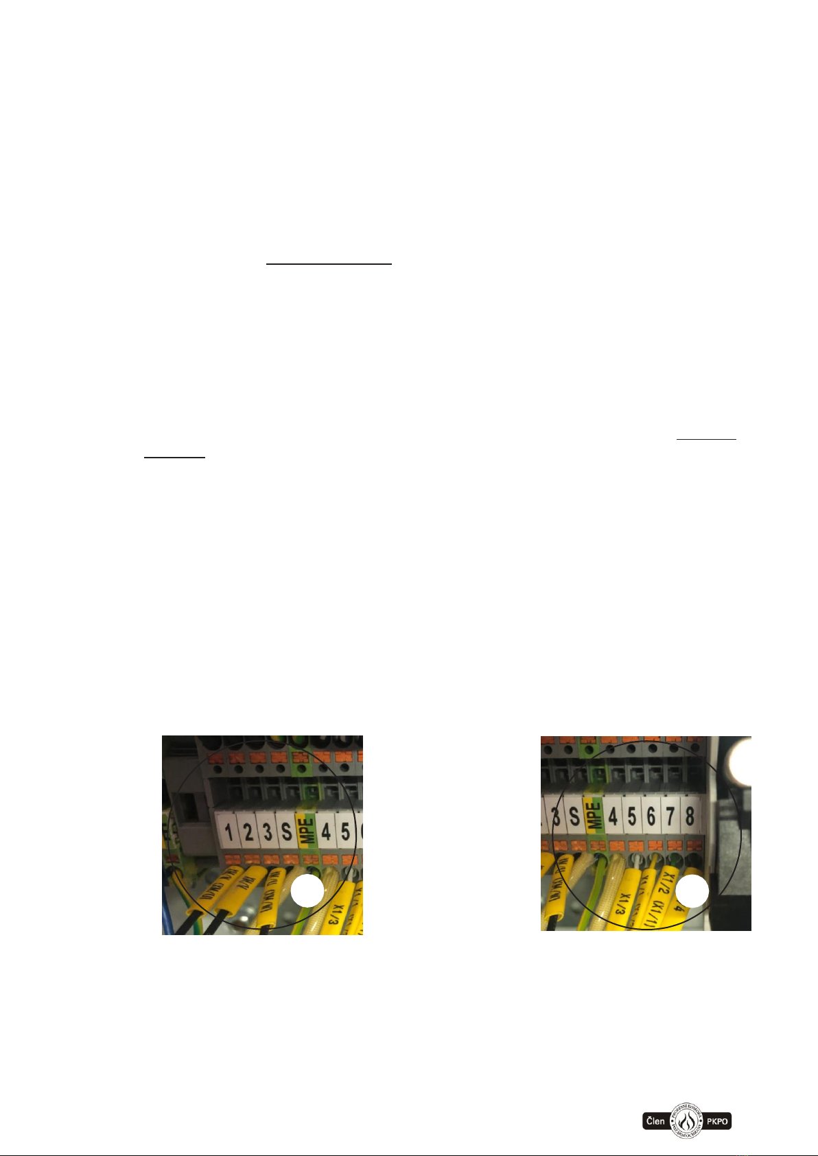
1. Motor cable FSTronic IRC-FI (can be part of motor)
-Motor power - terminal block X4 terminals 1, 2, 3, S, PE (picture 1.1)
oterminal 1 (motor phase) –wire marking XM/U (eventually 1)
oterminal 2 (fáze motoru) – wire marking XM/V (eventually 2)
oterminal 3 (fáze motoru) – wire marking XM/W (eventually 3)
note. - by switching the motor phases, it changes the direction of rotation
- see point 3.1.1 setting the direction of movement
oterminal S (shielding of motor cable) –grey wire without marking
oterminal MPE (ground) –wire green-yellow
-Communication cable of possition sensor IRC –end switches –terminal
block X4 nterminals 4, 5, 6, 7, 8 (picture 1.2)
oterminal 4 (shielding of sensor cable) –grey wire without marking
oterminals 5 a 8 (power supply for sensor 24V)
terminal 5 (0V) –sensor wire marking X1/3 (eventually 5)
terminal 8 (+24V) –sensor wire marking X1/4 (eventually 8)
note - the polarity of the sensor power supply must be correct!!
oterminals 6 a 7 (output signal from sensor)
terminal 6 –sensor wire marking X1/1 (eventually 6)
terminal 7 –sensor wire marking X1/2 (eventually 7)
note - the output signals of the sensor can be reversed, this changes the
direction and the direction of movement must be set / confirmed again,
see.point 3.1
1.2
1.1
www.somati-system.cz
5
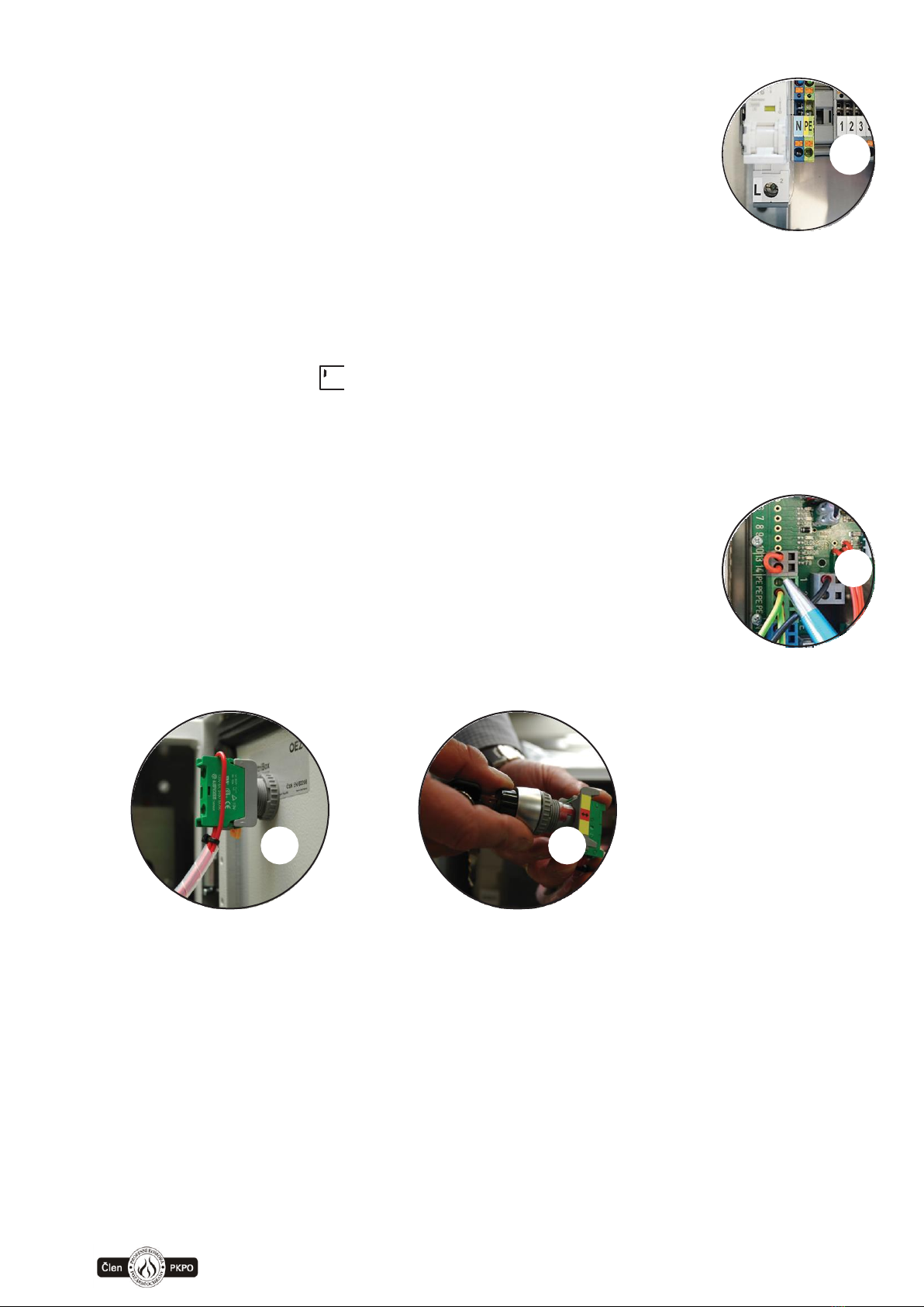
2. Power cable –terminal block X4 terminals L,N,PE
Necessary to connect all wires including
grounding. Without grounding (PE) can be unit
damaged.
After connecting the switchboard to the mains,
the batteries can be connected by inserting a
fuse into the disconnector, see point 3.7
3. Connect terminals EPS - fire contact
(X2:+ and X:10) by default set as input NC contact - can be
changed by parameter (default setting when the door is
open, the door is still in alarm). Originally supplied with the
wire jumper marked “fire contact”.
4. Terminals of safety brake - (X1:13 and X1:14)
or the IRC_FI version, this input is used to block the motor in
the closed position. The input is NO, if it closes in the closed
position then the motor is blocked - it is used for input of the
inductive sensor of the door hook lock. Do not connect the
terminals
5. Install key switch - due to transport is delivered disassembled
Note:
For version compact key switch is not part of standard
delivery. Can be additionally added.
2.
!
4.
5.
5.

www.somati-system.cz
6
6. External battery (voluntarily accessory), recommended only
original accumulators - 24V (2x12V) with fusing
7. Installation of the battery fuse. Fuse is delivered together with control unit,
but is not inserted in connector. Is fixed on the door of control unit. Fuse
type tubular fuse 10x38 gG32a.
Do not connect any external controls or any other devices before setting
the end switches –it can cause automatic start, which is not restricted
due to the unset end switches.
Steps for connection to power:
Connect power supply and only then connect batteries (see point 7.)
Steps for disconnecting power:
First disconnect batteries and then disconnect power supply.
6.
6.
6.
7.
7.
!
www.somati-system.cz
7
3.1. Setting of end switches IRC (incremental)
First check the value of parameter “r”, if is equal to used motor.
If the control panel has already been used in the past, we recommend performing a
complete reset of the control panel by calling the function , see the description
in point 3.2
After switching on the control panel power supply, which has already been set in the
past, an attempt will always be made to find the reference position. The display shows
. that no reference has been made (reference = end point search where the
IRC sensor is reset, by default the reference point is set to the closed position)
Subsequently, a message appears on the display or which indicates
that the door is looking for a reference point (r_CL = referencing to position closed,
r_OP referencing to position open, see parameter settings
The reference position is searched at reduced speed, see parameter settings
When searching for a reference at the moment of reaching the stop (end position),
the drive is overloaded and after the time set by the parameter has elapsed, it
evaluates as reaching the reference point and resets the position sensor.
Unintentional evaluation of the end position can occur if the motor is overloaded when
searching for a reference when there is no free movement of the door - check the
door mechanism.
If the control panel was set up correctly in the past and the door mechanism has not
changed, the drive is ready for use after searching for a reference point (reference).
During referencing, this process can be interrupted and new settings can be made,
proceed according to point 3.1.1
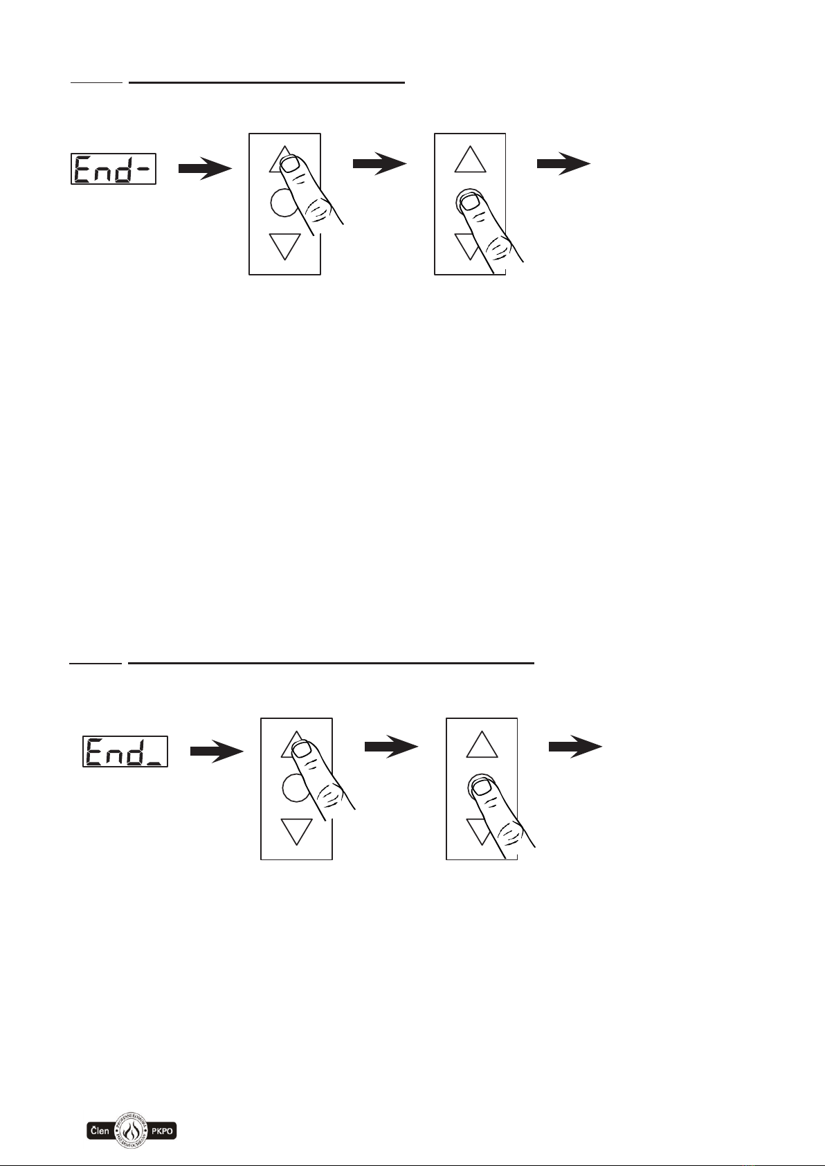
3.1.1. Setting of movement direction:
1. 2.
press 9s press 3s
press
5s
direction saved
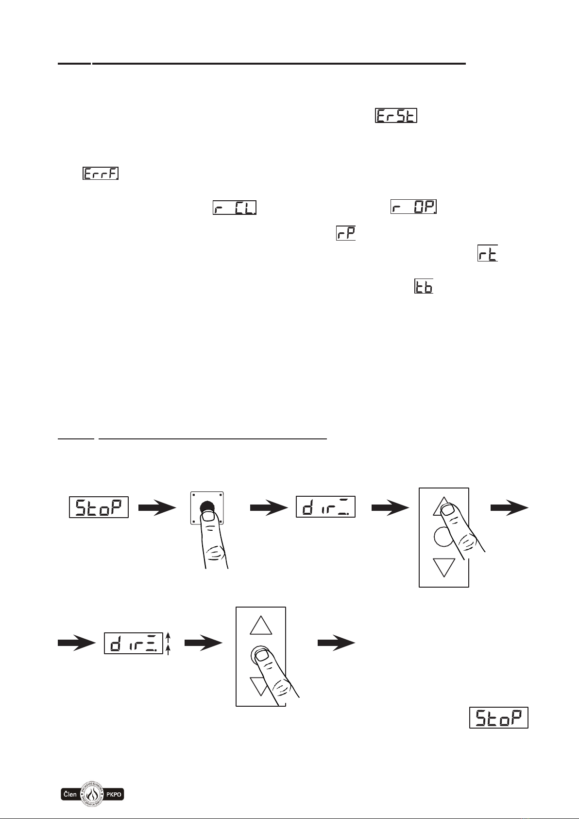
Setting is possible only from STOP state, “stop” must be shown on display.
1)
press and hold knob button –during approx. 9 s. it passes to setting of movement,
and display shows „ dir
ˍ
“
(by holding the knob button, after 4 seconds there is at first displayed „Par“ „Par“ it is
!
www.somati-system.cz
8
necessary to hold the knob button until display shows:
a)
„ dir
ˍ
“ –if two horizontal lines light, the direction has been already set
b)
„ dir
ˍ
“ –if two horizontal lines flash, the direction has not been set yet
2)
Afterwards press keyboard buttons “open” or “close” (keyboard has to be unlocked
by key switch), if the movement takes longer than 3 seconds, then three horizontal
segments, shown on the display, start rolling in direction specified with keyboard.
After releasing the button of movement direction, all three segments flashes:
•
if the actual direction of movement is different, it is necessary to switch 2 cable
phase conductors to motor and repeat point 2) setting of movement direction
•
if the direction of movement corresponds, it is possible to save the setting –which
can be done by pressing STOP button on keyboard and holding the button for 5
seconds.
After saving the direction of the movement (by holding STOP on keyboard for 5 seconds)
we automatically proceed to setting of end switches.
It is possible to skip setting of direction („dir“) by pressing knob button – to get directly
to setting of end positions. It is possible to use function „dir“ for manual movement of gate
in emergency situations –only used for service (for example in case of getting out of range
of end positions or during the activation of safety end switches).
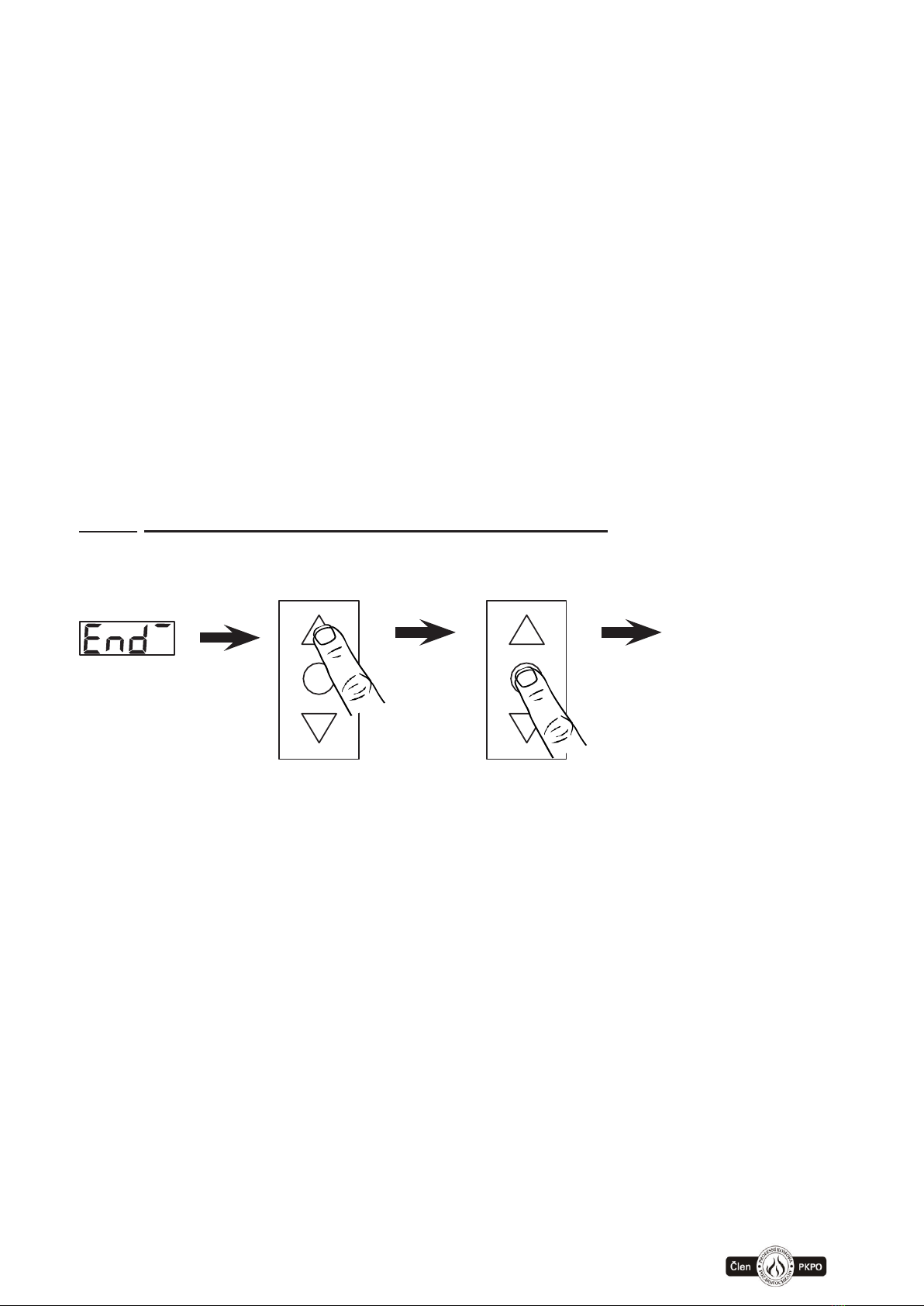
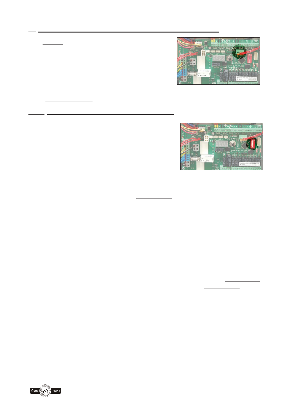
3.1.2. Setting of upper end position „opened“:
press press 5s
upper position
saved
1)
This setting is available automatically after saving the setting of direction or by
pressing knob button, the display shows:
a)
„End “ –if the upper line lights, the position has been already set
b)
„End “ –if the upper line flashes, position has not been set yet
2)
Afterwards press keyboard buttons OPEN or CLOSE (keyboard has to be unlocked
by key switch) and move gate into position, in which we want to set the end position
“opened”:
•
If the actual position of gate corresponds with the required position, it is possible
to save the setting –by pressing STOP button on keyboard and holding the
button
for 5 seconds.
•
After saving the upper end position (by holding STOP on keyboard for 5
seconds) we automatically proceed to setting of middle position.
•
It is possible to skip setting of upper end position (in case it has been already set)
by pressing button knob –then we proceed directly to setting of middle position.
www.somati-system.cz
9
3.1.3. Setting of middle position:
press press 5s
middle position
saved
1)
We can start setting of middle position after saving the position “opened” or by
pressing button knob, there is displayed:
a)
„End - “ –if the middle line lights up, the position has been already set
b)
„End - “ –if the middle line flashes, position has not been set yet
2)
Afterwards press keyboard buttons OPEN or CLOSE (keyboard has to be unlocked
by key switch) and move gate into position, in which we want to set the middle position.
•
If the actual position of gate corresponds with the required position it is possible to
save the setting –by pressing STOP button on keyboard and holding the button
for 5 seconds.
•
After saving the middle position (by holding STOP on keyboard for 5 seconds),
we automatically proceed to setting of lower end position.
•
It is possible to skip setting of the middle position by pressing the knob button –
and proceed to setting of the lower end position –IT IS NECESSARY TO SET the
middle end position to put the gate into standard operation, the middle position is
used for additional functions (e.g. emergency open…)
3.1.4. Setting of lower end position „closed “:
press press 5s
lower position
saved
1)
We can start setting of the lower end position after saving the middle position
or by pressing the knob button, on display is shown:
a)
„End ˍ “ – if the lower line lights, the position has been already set
b)
„End ˍ “ – if the lower line flashes, the position has not been set yet
2)
Afterwards press keyboard buttons OPEN or CLOSE (keyboard has to be unlocked
by key switch) and move gate into position, in which we want to set the lower end
position.

www.somati-system.cz
10
•
If the actual position of gate corresponds with the required position it is possible
to save the setting –by pressing STOP button on keyboard and holding the button
for 5 seconds.
•
After saving the lower end position (by holding STOP on keyboard for 5 seconds),
we automatically proceed to calibration of opening time.
•
It is possible to skip setting of the lower end position by pressing knob button –
and proceed to setting of the calibration of opening time.
It is possible to use function „End -“ setting of end positions, for manual movement of gate
in emergency situations –only used for service (for example, when passing the range of
end positions or during the activation of safety end switches).
To put the gate into operation, it is necessary to do final calibration of operation time.
This is a safety function, which is important when preparing gate for standard operation.
3.1.5. Calibration of time and torque (max. motor force)
Calibration of time and torque is a necessary task for the complete commissioning of the
door. If this function is not performed correctly, an error will be displayed, ie a
movement time error or a maximum torque error . This function is safety and is used
to check the movement time and the maximum torque during operation.
During calibration, the maximum running time between the end positions is measured also
the maximum torque when moving the door - this maximum torque can be exceeded during
standard door movement by the value set by the parameter , thus increasing insensitivity
in the event of an obstacle. The time for which the maximum torque can be exceeded is set
in parameters and
press press
Setting of calibration:
It is important to set lower (“closed”) and upper (“opened”) end position.
1)
Display shows „CL“ – by pressing keyboard button CLOSE –to get to position “closed”
(position “closed” has to be set). After setting the position “closed” the motor stops
and display shows „t OP“
2)
By pressing keyboard button OPEN and its holding (without interrupting) we get into
position “opened” (position “opened” has to be set). In “opened” position the motor
stops and unit goes to normal operation –setting of direction and positions
is successfully completed)
If the pressing/holding of keyboard button is interrupted before reaching the opened
position, the setting automatically returns to point 1) and it is necessary to repeat the
calibration process. You have to return to position “closed” and repeat the calibration
process.

www.somati-system.cz
11
It is possible to terminate the calibration by pressing knob button –however, thecalibration
of time is not set and the unit cannot work automatically.
3.2.Complete reset of unit
If necessary it is possible to make complete reset (e.g. in case of using on other motor).
Deletes end positions calibration of the time all parameters will be set to default and
parametr “r” will be set for weakest motor r=1.
Deleting is possible only from STOP state, on display must be shown
Press and hold knob button –after approx. 20s the delete operation
starts, on display is shown “ErSt”. Reset must be confirmed.
a)
If we press knob button –we return to STOP state without deleting)
b)
If we turn the knob, select “YES” and press knob button –the deletion is accomplished
and we return to “STOP”.
c)
If we turn the knob, select ESC and press knob button –we return to STOP
without deletion.
4. Connection of other external devices
After testing the setting of end positions (IRC) it is possible to continue with connection of
other external devices.
Control box FSTronic DES-FI is standardly equipped with keyboard buttons „Open“ and
„Close“, which can be used to open the gate in “Dead man” mode. For automatic operation
(one- press start) upwards, it is necessary to connect terminals X2:+ and X2:3 by connection
or safety device. If it is possible to hang on the surface of gate leaf or to pass an object
through the gate, it is necessary to add a safety device “upper safety sensor” to maintain
automatic operation
Automatic operation close is activated by connecting safety sensor „lower safety sensor“
with terminals X2:+ and X2:2 („lower safety sensor“) or by connecting optical safety edge
OSE with terminals X2:G and X2:W and X2:B (ATTENTION - OSE safety bar must be
activated, see 5.2.1 - DIP8. If the safety sensor is disconnected (or OSE or contact strip is
activated) during closing, gate moves back and stops (see setting of DIP6 and selection of
parameter „4“).
In case the „lower safety sensor“ is disconnected (or OSE or contact strip is activated)
permanently, it is possible to close the gate in “Dead man” mode. “Lower safety sensor” has no
influence on opening of gate.
It is also possible to connect safety contact strip of the system with closed loop by resistance
(8,2kΩ) –this function is identical with the function of OSE or “lower safety sensor”. If the contact
strip is not connected, terminals X2:39 and X2:40 has to be connected to resistance 8,2kΩ -
without the resistance the automatic operation does notwork.
When pull switch (X2:8) is activated, gate opens into the open end position and remains
in this position for a time set in parameter „6“, then the gate automatically closes.
Control Step-by-step (X2:7) enables to open and close gate with a single button. When we press

www.somati-system.cz
12
the button, the gate starts to open to the end position or stops after we press the button again.
When we do another press of the button, the gate starts to close to the end position or after another
press of the button the gate stops. The gate can be stopped anytime with button STOP.
When EPS (fire alarm system) is activated –contact between X2:+ and X2:10 is disconnected
and gate is in alarm mode = the gate immediately closes (if there is not set a closing time
for delayed closing –pre-flash) or opens in case of set functionality for “ventilation”.
In the event of a power failure, the door will remain in the open position according to the setting
of parameter "8". If the parameter "8" is set to "-", the battery capacity is controlled and they
remain in position for a maximum of until the voltage on the backup battery falls below the 22
V threshold (the time depends on the condition and charge of the battery). Then they close to
the lower end position by closing as in the alarm state.
During the alarm closing it is possible to stop the gate with STOP button–it is stopped as long
as the button is held, „lower safety sensor“ or optical safety edge OSE stops the closing without
moving back. If the „lower safety sensor“ or optical safety edge OSE is disconnected longer
than time set in parameter (default 10 sec), the gate starts to close again.
In case the gate is closed by fire alarm (EPS, detectors..), it is possible to do an emergency
open into the middle position using button Emergency open (X2:9). In the middle position (set
according to parameter ”9”) gate remains for the set time in parameter „A“, then it is closed like
in alarm mode. A pre-flash is not set before this emergency open. The function only applies in
case of present power supply 1x230V or if the backup power is correctly dimensioned. In
parameter „O“ –it is possible to select maximum of 10 attempts to open, however it is
dependent on status of battery charge and its size.
Function of audio and visual signalization (Pre-flash) causes that during the set time
in parameter „2“, before the standard operation of gate, signalization starts functioning (flash
and sound = warning light). When using function „Pre-flash“ and „Dead man“ it is necessary to
permanently hold pressed button in required direction of gate movement and wait until the end
of set time of pre-flashing before the gate starts moving into the required position
IF SAFETY DEVICES (FUSES) IN CONTROL BOX ARE BLOWN,
IT IS POSSIBLE TO TURN THEM ON ONLY ONCE –IF THEY ARE
BLOWN ONCE MORE, IT IS NOT PERMITTED TO TURN THEM ON
AGAIN
IF THE PROCEDURE STATED IN THE TECHNICAL DOCUMENTATION
IS NOT RESPECTED, IT MAY LEAD TO THE LOSS OF WARRANTY
IN THE EVENT OF MALFUNCTION, FIRST IT IS NECESSARY TO DETECT
POSSIBLE CAUSE OF THE MALFUNCTION AND REPAIR IT. AFTER
THE MALFUNCTION IS REPAIRED, IT IS POSSIBLE TO TURN
ON THE BLOWN FUSE
AGAIN.
IT IS FORBIDDEN TO MANIPULATE WITH CIRCUITS OF THE
CONTROL BOX AND CHANGE THEIR CONNECTIONS. IN THE EVENT OF
FAILURE TO COMPLY WITH THIS CONDITION, IT IS NOT POSSIBE TO
APPLY WARRANTY ON THE CONTROL BOX
CONTROL BOX CANNOT BE OPENED BY A PERSON WITHOUT APPROPRIATE
TRAINING AND QUALIFICATION ACCORDING TO THE DECREE No. 50/1978, §6
www.somati-system.cz
13
5. Description of control and terminal blocks
5.1.
Func
Terminal block of function FUNC is used to internal functional
connection of the control box, nothing has to be connected
on this terminal block.
5.2. DIP switch
5.2.1 Description of DIP switch functions
DIP1 –activates signalization of lower safety
sensor on LED indicator
DIP2 –activates upper safety sensor on LED indicator
DIP3 –activates automatic closing after opening by pressing “open” button on the
keyboard of control panel, “open” button has same function in case of activation as
pull switch (i.e. after setting time in parameter „6“, gate is automatically closed)
DIP4 –activates shortening of automatic closing time when passing safety sensor.
If the function is activated and safety sensors are installed, the gate immediately
closes when passing the safety sensor and does not wait to the end of the set time
in parameter „6“
DIP5 –selects if lock on the control panel only locks the panel buttons (open /close)
or it also locks all external inputs on the terminal block (e.g. remote control...)
DIP6 –selects response mode to collision with an obstacle during closing. It is possible
to select either 1) that the gate only moves back and then stops or 2)
that after collision the gate fully opens and after the end of set time in parameter „5“
it tries to close again (number of attempts for closing is set by parameter „4“)
DIP7 –no function
DIP8 –activates signalization of safety edge OSE –in case safety edge OSE
is not connected, it is necessary to cancel its signalization on the panel. If OSE
is connected, then we have to activate its function.

www.somati-system.cz
14
5.2.2. Description of setting functions on DIP SWITCH
POSITION OFF ON
1 lower safety sensor
ON
OFF
2 upper safety sensor
ON
OFF
3 “open”button
Placed on control panel
OFF
ON
4 shortening of closing
when passing safe. sensor
OFF
ON
5 locking of external
inputs impulse+pull
OFF
ON
6 detection of obstacle
during automatic closing
fully opened
partly closed
7 no function
8 activation of OSE
OFF
ON

www.somati-system.cz
15
5.3. Description of functions on display device
5.3.1. Control of menu on display
press 1x
1x press showes actual version of program.
press 4s press 1x
Description of setting of optional parameters on display device. To enter the setup we have
to hold knob button and after 4 seconds display shows „Par“.
parameter 1 on value 0
press 1x
changing parameter 1
on value 1
by turning change
the parameter
After displaying „Par“ press knob button to display the individual parameters and their set
value.
By turning the knob button you can display individual parameters and after pressing
the knob button you can start to change the set values of the particular parameter –the
value flashes. The parameter value can be changed by turning the knob button and after
reaching the required value, it can be saved by pressing the knob button. If we do not want
to change the parameter value, then we have to turn by the knob until the display shows
„ESC“ and then by pressing the knob button we move forward.

www.somati-system.cz
16
5.3.2. Parameters and their values
Parameter - Audio & visual signalization
- warning light (output X2:26, X2:27)
during movement during alarm
•0 = active with delay active with delay, during alarm duration
•1 = not active active with delay, during alarm duration
•2 = active without delay active without delay, only during movement
•3 = not active active without delay, only during movement
•4 = not active active with delay, only during movement
Parameter –Time of pre-flash - alarm
Range of values: 0–999 seconds,
Note: In case of setting time delay follow rules in standard EN 14637.
Default = 0
Parameter –Time of pre-flash under normal operation
Range of values: 0–999 seconds,
Note: (when setting parameter „1“ “warning light” on value 1, there is running only
the time of pre-flash, warning light is not active)
Default = 0
Parameter –number of attempts to close
Range of values:
•0-10 attempts
•„-„ = endless number of attempts
Note: (according to the setting DIP6 gate moves back or fully
opens) Default = 0
Parameter –delay of closing attempts
Range of values: 1–50
seconds Default = 10
Parameter –time of automatic closing
Time after which the gate, opened by pull switch, starts to
close. Range of values: 3–999 seconds
Default = 10
Parameter –duration of movement back
Motion back after collision with obstacle.
Range of values: 1–10 seconds
Default = 3

www.somati-system.cz
17
Parameter –time of battery discharging
Time after which the gate, held on batteries, closes during power
failure. Range of values:
•0-30 minutes
•„-„ = depends on battery condition and
load Default = 10
Parameter –Emergency Open width
Setting of width for automatic open in alarm and activation of button
Emergency Open (input X2:+, X2:9) Range of values:
•30–100 % gate width
•„-„ = according to the setting of middle position
Note: When we have end switches NES it is possible to set only „-“ and the position
follows the setting of middle position.
Default = 50%
Parameter –Emergency Open time
Setting of time during which the gate waits in the set position
after activation of button Emergency Open.
Range of values: 5–999
seconds Default = 10
Parameter –Permanent Open
Selection of input function of pull switch (input X2:+, X2:8)
•0 –without permanent open –standard pull switch
•1 –function “permanent open” is activated – if the input of pull switch
is connected then it opens always when it is possible –closes only in alarm
•2 –function permanent
close Default = 0
Parameter –Return after alarm
What happens after cancelling the alarm:
•0 = after cancelling the alarm, do nothing
•1 = return to the state before alarm
•2 = after alarm Open
•3 = after alarm Close
•4 = after alarm Reset will finish closing as the alarm will be
active Default = 0
Parameter –Passing of closed position
Is used to pass the end position “closed” during alarm – can close the
door beyond the end position when closing the alarm - special
application.
Range of values: 0–100 % from 6 % gate height. Default = 0
www.somati-system.cz
18
Parameter –time of Smoke alarm
Time in which the gate remains in alarm „Smoke“ i.e. in
position partly opened before closing again:
•5–999 seconds
•„-„ = time unlimited
Default = 10
Parameter –length of opening time in case of Smoke alarm
activation
•0–100% gate width
•„-„ = according to the setting of middle position
Note: When we have end switches NES it is possible to set only „-“
and position follows the setting of middle position.
Default = 50 %
Parameter –do not monitor OSE / Ledge 8K2
The width from which the safety edge of OSE
is not monitored to prevent the unwanted opening before the contact with stop profile.
Range of values: 1–100 % from 10 promiles of gate width
Default = 30 %
Parameter –correction of the end position “opened”
Range of values: -99 –+99 % from 1 % gate height
Default = 0
Parameter –correction of the end position“closed”
Range of values: -99 –+99 % from 1 % gate height
Default = 0
Parameter –selects type of motor for correct setting of
frequency inverter
We select the type of motor and the control box enters,
into the frequency inverter, the appropriate parameters
of the particular motor for its proper and smooth operation.
Note: Control boxes FSTronic IRC-FI are supplied in two sizes of frequency inverter see
the table, point 2.
Value „r“
Motor type
Type od sensor
Power of
inverter
1
EPO 120W
IRC
2 A
2
EPO 180W
IRC
2 A
3
EPO 250W
IRC
4 A
www.somati-system.cz
19
Value „r“
Motor type
Type od sensor
Power of
inverter
4
EPO 350W
IRC
4 A
„-„
Individual motor
settings
„-„ = motor parameters according setting on
frequancy inverter
note: Warning, this value can be used only
based on agreement with the producer. Only
for special applications for non-standard
motors.
Parameter –attempt to open gate using backup power
-0–10 attempts
Default = 0
This parameter is significantly dependent on sizing of backup power hardware according
to the motor size and gate dimensions. Backup power is primarily designed only for
closing of gates.
Note: No influence on setting function ventilation
Parameter –opening speed
Range of values: 40–250 %
Value shows how many percents from maximum frequency 50 Hz
(primary set on frequency inverter) will be the speed of opening (100
% = 50 Hz)
Default = 80 %
Parameter –closing speed
Range of values: 40–150 %
Value shows how many percents from maximum frequency 50 Hz
(primary set on frequency inverter) will be the speed of closing (100 %
= 50 Hz)
Default = 80 %
Parameter –acceleration time
Range of values: 10–50 (1–5 seconds) steps 0,15
Value shows length of acceleration ramp in seconds (35 = 3,5 seconds), higher value
means slower and smoother motor acceleration.
Default = 1,5 seconds
Parameter –field of deceleration open possition
Range of values: 1–10 %
Value of the lenght distance before reaching open end possition.
Value is shown in percent of traveling distance.
Default = 3 %

www.somati-system.cz
20
Parameter –field of deceleration closed possition
Range of values: 1–10 %
Value of the length distance before reaching bottom end possition.
Value is shown in percent of traveling distance.
Note: In case of roller gate influenced by non linearity of roll up diameter.
Default = 3 %
Parameter –cross optocell
Possible to set functionality of safety sensor (input X2:+,X2:2) for cross connection.
Opportunity to use two optocells with cross safety beams under door leave. During closing
gate will be functionality of safety sensor deactivated when reached position set by LS1
so moving door leaf will not activate the sensor. Necessary to set right possition LS1.
When this parameter set on value 1 then safety sensor between LS1 and bottom
possition is not active. (Typical application for conveyors –vertically moving door)
Range of values:
•0 = normal
•1 = cross optocell
Default = 0
Parameter –speed in alarm mode
Range of values: 20–150 %
Value showes how many percents from maximum frequency 50 Hz
(primary set on frequency inverter) will be the speed in case of alarm
(100 % = 50 Hz).
By reducing of this speed possible to reach longer operation from battery backup.
Default = 40 %
Parameter - service period (cycles)
service period 1 - 50 cycles, steps in 1000 cycles
Note: 0 = 10 cycles
Default = 3 (3000 cycles)
Parameter - conveyor confirmation
type of reaction when activated input “SMOKE” (X2:43 and X2:44)
0 = standard function “SMOKE”
1 = conveyor confirmation - in case of alarm and running time delay can be gate closed
immediately when activated this input. When conveyor is clear gate can close quicker.
Default = 0
Parameter - initial alarm braking time
Allows you to select the length of the stop time in case of the FIRST
activation of the safety device during closing in alarm.
Range of values: 1–999
second/s Default = 10
This manual suits for next models
4
Table of contents
Popular Control Unit manuals by other brands

Continental Refrigerator
Continental Refrigerator FE4CNX210 Manual and user guide

IBM
IBM 3274 user guide

National Instruments
National Instruments 9225 CALIBRATION PROCEDURE

Automationdirect.com
Automationdirect.com Productivity 1000 P1-08TA manual

A.R.I.
A.R.I. Eliptix R-30 S 2W Installation, Operating, Maintenance

Nakanishi
Nakanishi E3200 Series Operation manual


