Henderson Prometheus User manual

INSTRUCTIONMANUAL
XS-2/230V Motor Prometheus
Product group: Sliding shutters, -windows, -doors,
Version: 1.4
Language: english
Orig. Language: german
Document: ------

1
About this document
www.baier- g mbh.de
1.4 Used Symbols
Hint
A hint gives important and additional information.
N O T I C E
Description of type and source of hazards
Warnings, marked with this symbol, are related to safety.
Disregard may result in property damage.
Steps to avoid hazards.
C A U T I O N
Description of type and source of hazards
This symbol indicates a hazardous situation which, if not
avoided, could result in minor or moderate injury and/or
property damage.
The following levels of warning show the severity and
probability of possible hazards, in ascending order.
CAUTION, coloured yellow
WARNING, coloured orange
DANGER, coloured red
Steps to avoid hazards.
symbolizes a list with no specific order
1. symbolizes a list or instruction in specific order
symbolizes an action
symbolizes a reference
symbolizes the result of the action
List
Instruction

www.b aier- g mbh.de
2
Safety
2Safety
D A N G E R
Electric Shock
Danger to life and health due to electrical shock.
Electrical connections have to be installed by approved
personnel only
Switch off power before carrying out work and secure
power against being switched on.
Observe relevant safety instructions.
2.1 Requirements for operation
Hint
Read the instruction manual before performing the initial operation.
2.1.1 Environmental conditions
The Prometheus XS-2/230 motor is designed for use in protected outdoor areas. It must
not be exposed to direct moisture, such as rain. More information can be found in the
datasheet.
2.2 Intended Use
This product serves as a drive for sliding shutters, sliding doors and sliding windows. It is
connected directly to the 230V, 50Hz AC mains supply. Various connection options are
available.
The manufacturer’s instructions for dimensioning, i.e. maximum and minimum
dimensions, maximum weights and similar details must be observed.
Any other use of this product shall be considered as improper use.
We cannot guarantee that the product will work with fittings, controls or other electronics
from other manufacturers.
2.3 Behavior in case of an error
In case of an error, the device must be shut down and the manufacturer must be
informed.
Do not operate device
Disconnect device from power supply
Inform the manufacturer
Shut down

3
Functional Description
www.b aier- g mbh.de
3Functional Description
Construction and Function of the Motor
The motor’s internal construction consists of a 24V DC motor, the electronics and a mains
adapter. The motor usually drives a sliding shutter or a sliding door via a toothed belt.
The motor always has 4 wires in the connection cable. The connection of these cables
determines the type of operation:
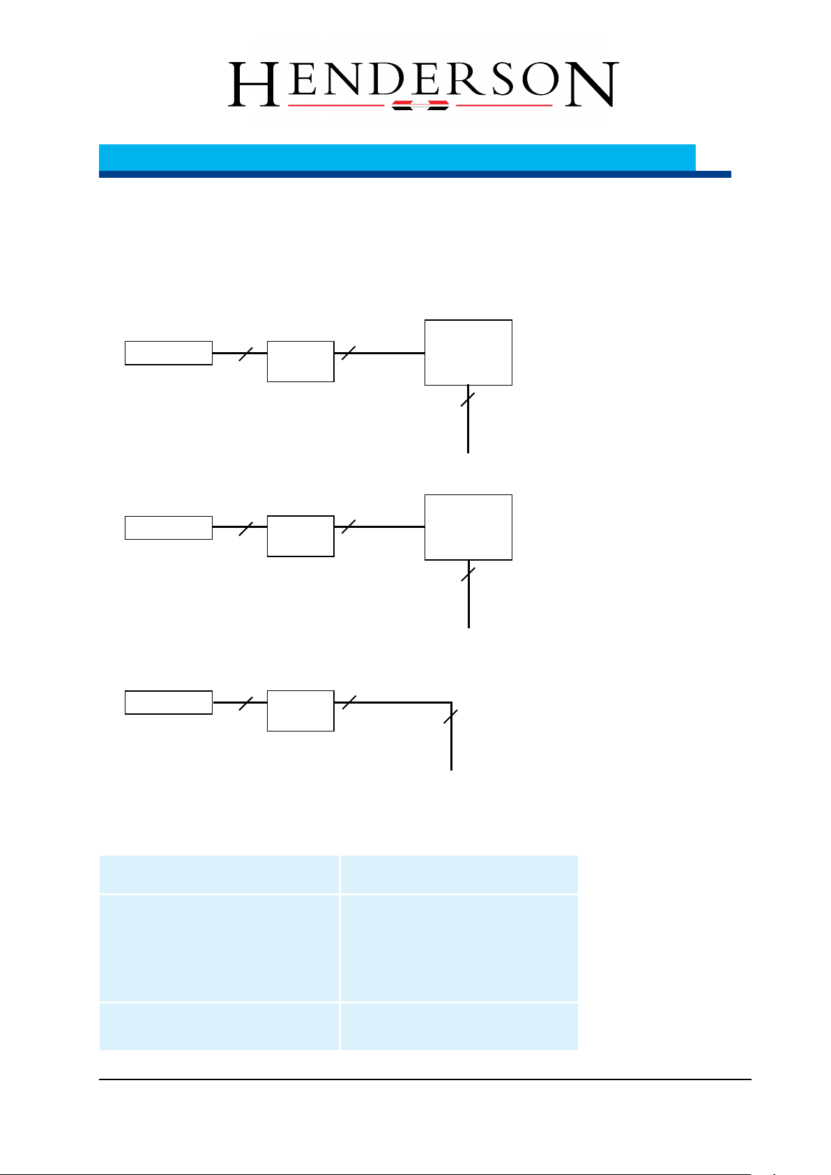
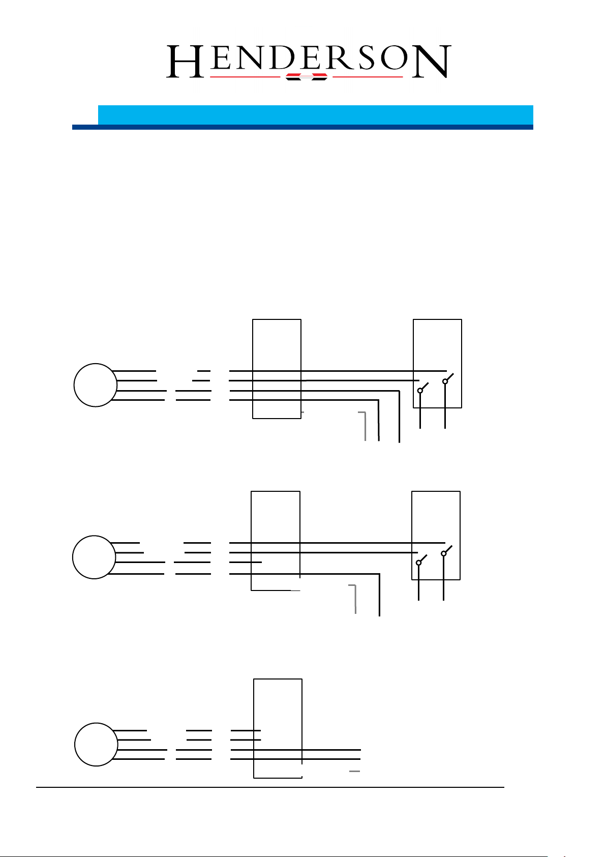
4-Wire Connection, Automatic optional with wireless control
The following connections are made for the 4-wire connection: L (phase, permanent), N
(neutral wire), Open (L phase) and Closed (L phase).
The motor is normally permanently supplied with voltage. If one of the two control inputs is
connected with voltage, the motor starts to run in the desired direction. The control signal
need not be on continuously during the run; a short pulse is sufficient.
The motor stops when an obstacle is detected, if a pulse is given off in the opposite
direction or the end of the track is reached.
3-Wire Connection, Deadman no wireless control possible
The following connections are made for the 3-wire connection:
N (neutral wire), Open (L phase) and Closed (L phase).
L (phase, permanent) is not connected.
The motor is only supplied with voltage via the control inputs. If one of the two control
inputs is connected with voltage, the motor starts to run in the desired direction. The
control signal must stay on continuously during the run.
The motor stops when an obstacle is detected or the end of the track is reached. The
motor also stops when the control signal goes off.
2-Wire Connection, with mandatory wireless control
The following connections are made with the 2-wire connection:
L (phase, permanent) and N (neutral wire).
Open (L phase) and Closed (L phase) are not connected.
The motor is normally permanently supplied with voltage. It is actuated via an integrated
wireless receiver. Once it is activated, the motor starts to run in the desired direction. The
wireless signal need not be on continuously during the run; a short pulse is sufficient.
The motor stops when an obstacle is detected, if a wireless pulse is given off in the
opposite direction or the end of the track is reached.
Wireless Transmitter and Receiver
Optionally, the motor has an integrated wireless receiver for actuation.
With the 4-wire connection, the wireless control can be used optionally for actuation in addition to
on-site button.
With the 3-wire connection, the wireless control cannot be used effectively, due to the non-
permanent voltage supply.
With the 2-wire connection, the wireless control must be used for actuation

www.b aier- g mbh.de
3
Functional Description
Configuration and Commissioning
The motor has no other setting or configuration options. It is ready for operation after
installation. No additional steps are required for commissioning.
Power Shutdown
The integrated motor control unit serves to operate the motor until such time as it
exceeds the permissible torque. This function is called a power shutdown. This allows
the drive to detect obstacles and shut down.
The power shutdown is also used to detect the end positions. Since the motor’s
power consumption increases at the end positions, the drive shuts off.
Low Speed Operation
During the first run, the integrated motor control unit determines the duration of a
normal run. Shortly before the end of this period, the motor runs at reduced speed to
save the mechanics and increase safety.
Likewise, the motor also runs at reduced speed if it shuts off before the end, due to
the power shutdown.
Connecting in Parallel
Several motors can be connected in parallel to one control switch. One motor can be
connected in parallel to multiple control switches. The maximum switching capacity of
the installation should be observed in doing so.
3.1 Dimensions
The control unit is generally located in the motor extension and is firmly connected to
it. The dimensions are approximately 52 x 60 x 225 mm (WxHxL), excluding mounting
block and cable.
.

4
Cable installation
www.b aier- g mbh.de
4Cable installation
4.1 Cable diagrams
4.1.1 4-wire connection
4.1.2 3- wire connection
4.1.3 2- wire connection
4.2 Wiring requirements
The following specifications are minimum requirements.
Wire
Type of wire
between elec. connection and motor
Preassembled cables to the motor
1. H05RN-F (o. glw.)
4 x 0,75 mm², length. 0,5m
without special wire
Optional other type of wire,
Other lengths and connections
available..
between elec. connection and button
and between button and power line
site depending on requirements
Table 1 –Type of wire
power line
230V~ 50 Hz
2 (3)
2
(3)
N
L
(PE)
power line
230V~ 50 Hz
power line
230V~ 50 Hz
2 (3)
Motor
button
On site
/
4
(5)
N
L
open
close
(PE)
connection
(on site)
4
Motor
connection
(on site)
2 (3)
4
Motor
button
On site
/
3
(4)
N
open
close
(PE)
connection
(on site)
4

www.b aier- g mbh.de
5
Connection
5 Connection
5.1 Completing the electrical connections
Disconnect power supply
secure shutdown
safety instructions, see chapter 2
do connections as indicated
The motor is connected
5.2 4-wire-connection
5.3 3-wire-connection
5.4 2-wire-connection
N
PE
yellow/green
N
N
4
Button
(on site)
L
open
(L)
close
(L)
Connection
(on site)
Motor
close (L)
(L)
open (L)
L
3
2
1
Button
(on site)
N
open
(L)
close
(L)
Connection
(on site)
Motor
close (L)
L
3
N
4
PE
yellow/green
2
1
open (L)
L
connection
(on site)
Motor
L
PE
yellow/green
N
4
2
1
3
open (L)
close (L)

6
Wireless Receiver
www.b aier- g mbh.de
6Wireless Receiver
An integrated wireless receiver in the engine is available for operation using one or
more wireless transmitters. The wireless receiver is already installed at the factory and
is ready for use without any further connections.
6.1 Programming Wireless Transmitters
The wireless receiver can be switched to the learning mode for teaching-in and
clearing wireless transmitters. For a unit with wireless transmitters that have not yet
been taught-in, this can be done for about 30 seconds after it has been switched on
or can be accomplished via an already taught-in wireless transmitter using the
learning button.
Note
A maximum of 32 wireless transmitters can be taught-in on one
wireless receiver.
6.1.1 Teaching-in the First Wireless Transmitter
If no wireless transmitter has been taught-in on the wireless receiver yet, the wireless
receiver will be in learning mode for about 30 seconds after being switched on.
Supply motor and thus wireless receiver with voltage
The wireless receiver will be in learning mode for about 30 seconds
Briefly press the learning button on the desired wireless transmitter (<1.6 seconds)
The wireless transmitter’s LED flashes at 1-second intervals
Briefly press one of the function buttons (Open, Closed or the like) on the desired
wireless transmitter (<1.6 seconds)
The wireless transmitter has been taught-in
Learning mode is automatically exited
6.1.2 Teaching-in Additional Wireless Transmitters
If one or more wireless transmitters have already been taught-in, for example using
the above-described procedure or in the factory, the wireless receiver is switched to
learning mode using one of the wireless transmitters that has already been taught-in.
Supply motor and thus wireless receiver with voltage
Briefly press the learning button on the already taught-in wireless transmitter (<1.6
seconds)
The already taught-in wireless transmitter’s LED flashes at 1-second intervals
Briefly press one of the function buttons (Open, Closed or the like) on the already
taught-in wireless transmitter (<1.6 seconds)
Learning mode is activated for about 10 seconds
Briefly press the learning button on the desired wireless transmitter (<1.6 seconds)
The already desired wireless transmitter’s LED flashes at 1-second intervals

www.b aier- g mbh.de
6
Wireless Receiver
Briefly press one of the function buttons (Open, Closed or the like) on the desired
wireless transmitter (<1.6 seconds)
The wireless transmitter has been taught-in
Learning mode is automatically exited
Der Lernmodus wird automatisch verlassen
Clearing Wireless Transmitters with Taught-in Wireless Transmitter
All wireless receivers can be cleared in order to reset the wireless receiver to factory
settings and teach-in the desired wireless transmitter again. An already taught-in
wireless transmitter is required for this purpose.
Supply motor and thus wireless receiver with voltage
Press and hold down the learning button on the already taught-in wireless transmitter
for a longer time (<5 seconds)
The already taught-in wireless transmitter’s LED flashes rapidly
Press and hold down one of the function buttons (Open, Closed or the like) on the
already taught-in wireless transmitter for a longer time (<5 seconds)
All wireless transmitters have been cleared
Disconnect motor and thus wireless receiver from voltage source
The wireless transmitter comes with factory settings installed, without any taught-in
wireless transmitters
6.1.3 Emergency Teach for lost remote controls
If none of the learned transmitters be available, must be taught new, to the so-called
emergency learning needs to be performed.
Note
Run this emergency learning only if the already memorized radio
transmitters are not available. For all other cases, the procedures
described in advance are more comfortable.
supply power to the motor, and also to the wireless receiver,
do as described in the followed: 4 times the motor and thus the radio receiver
must be switched on and off, with the fifth turning on the wireless receiver it is
back in the learning mode for 30 seconds.
Supply motor and thus wireless receiver away from voltage
Supply motor with voltage (<0,5 seconds)
and disconnect immediately.
Stop of the first turn on process
Supply motor and thus wireless receiver away from voltage for min. 10 seconds
Supply motor with voltage (<0,5 Sekunden)
and disconnect again immediately.
Stop of the second turn on process
Supply motor and thus wireless receiver away from voltage for min. 10 seconds

6
Wireless Receiver
www.b aier- g mbh.de
Supply motor with voltage (<0,5 seconds)
and disconnect again immediately.
Stop of the third turn on process
Supply motor and thus wireless receiver away from voltage for min. 10 seconds
Supply motor with voltage (<0,5 seconds)
and disconnect again immediately.
Stop of the forth turn on process
Keep the motor away from voltage
the wireless receiver it is back in the learning mode for 30 seconds
The teaching in of the wireless receiver can be done like described in chapter 6.
This is now an additional wireless receiver all in former times teaches receivers
are still in function.
If the learning mode is not used, i.e. it can be taught no new wireless receiver or
the motor disconnected again from the power, so the already memorized
wireless receiver remains programmed.
The complete procedure must be repeated again if necessary.
Part Number: 100131
Level: 01
This manual suits for next models
1
Table of contents