Doosan DE08TS User manual

DE08TS Diesel Engine
Specification
System Operation
Testing & Adjusting
D100, D120, D150
D110S-5, D130S-5, D160S-5
SB4097E02
Sep. 2011


Important Safety Information
Most accidents involving product operation, maintenance and repair are caused by failure to observe basic safety
rules or precautions. An accident can often be avoided by recognizing potentially hazardous situations before an
accident occurs. A person must be alert to potential hazards. This person should also have the necessary
training, skills and tools to perform these functions properly.
Read and understand all safety precautions and warnings before operating or performing lubrication,
maintenance and repair on this product.
Basic safety precautions are listed in the “Safety” section of the Service or Technical Manual. Additional safety
precautions are listed in the “Safety” section of the owner/operation/maintenance publication.
Specific safety warnings for all these publications are provided in the description of operations where hazards
exist. WARNING labels have also been put on the product to provide instructions and to identify specific hazards.
If these hazard warnings are not heeded, bodily injury or death could occur to you or other persons. Warnings in
this publication and on the product labels are identified by the following symbol.
Improper operation, lubrication, maintenance or repair of this product can be dangerous and could result
in injury or death.
Do not operate or perform any lubrication, maintenance or repair on this product, until you have read
and understood the operation, lubrication, maintenance and repair information.
Operations that may cause product damage are identified by NOTICE labels on the product and in this
publication.
DOOSAN cannot anticipate every possible circumstance that might involve a potential hazard. The warnings in
this publication and on the product are therefore not all inclusive. If a tool, procedure, work method or operating
technique not specifically recommended by DOOSAN is used, you must satisfy yourself that it is safe for you and
others. You should also ensure that the product will not be damaged or made unsafe by the operation,
lubrication, maintenance or repair procedures you choose.
The information, specifications, and illustrations in this publication are on the basis of information available at the
time it was written. The specifications, torques, pressures, measurements, adjustments, illustrations, and other
items can change at any time. These changes can affect the service given to the product. Obtain the complete
and most current information before starting any job. DOOSAN dealers have the most current information
available.
WARNING
1


DE08TS Diesel Engines Index
Index
General Information
General Repair Instructions......................................5
Engine Specific Character........................................5
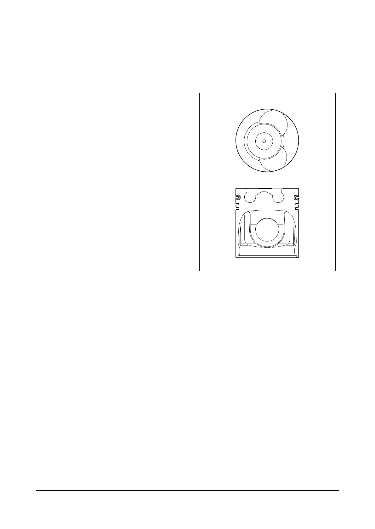
OMEGA Combustion bowl................................5
Engine Specifications...............................................6
Specifications....................................................6
Remove & Install Forks ....................................7
Performance curve(DE08TS-140PS) ...............8
Performance curve(DE08TS-160PS) ...............9
Engine Assembly....................................................10
Engine sectionnal view(longitudinal)...............10
Engine sectionnal view(cross) ........................11
Engine assembly view....................................12
Major Maintenance
Preventive Maintenance.........................................13
Cooling Water.................................................13
Fan belt...........................................................14
Engine Oil.......................................................14
OIl filter ...........................................................15
Fuel filter.........................................................15
Valve clearance adjust procedure ..................15
Cylinder compression pressure......................16
Injection nozzle...............................................17
Fuel injection pump.........................................17
Air removal of fuel system..............................17
Fuel supply pump ...........................................17
Turbocharger ..................................................17
Starting motor.................................................17
Diagnosis and Remedy..........................................18
Maintenance
Engine Disassembly...............................................27
Heed at disassembly ......................................27
Oil level gauge................................................27
Engine oil........................................................27
cooling fan ......................................................27
Belt..................................................................27
Thermostat......................................................27
Starter.............................................................28
Fuel filter.........................................................28
Breather..........................................................28
Alternator ........................................................28
Oil cooler.........................................................28
Oil filter............................................................29
Air compressor (if equipped) ..........................29
Idle pulley........................................................29
Water pump ....................................................29
Cylinder head cover........................................30
Fuel injection nozzle.......................................30
Turbo charger .................................................30
Exhaust manifold............................................30
Intake manifold ...............................................31
Cooling water pipe..........................................31
Rocker arm.....................................................31
Cylinder head..................................................32
Oil pan ............................................................32
Vibration damper.............................................33
Timing gear case cover ..................................33
Oil pump .........................................................33
Piston and connecting rod..............................33
Cylinder liner...................................................34
Camshaft gear and idle gear..........................34
Fuel injection pump.........................................35
Water chamber cover .....................................35
Fly wheel.........................................................35
Fly wheel housing...........................................35
Injection pump drive gear...............................35
Timing gear case............................................36
Bearing cap.....................................................36
Crankshaft.......................................................36
Camshaft and tappet ......................................36
Oil spray nozzle..............................................36
Inspection and Measurement on Major Parts........37
Cylinder block.................................................37
Cylinder head..................................................37
Rocker arm assembly.....................................41
Camshaft.........................................................42
Crankshaft.......................................................43
Fuel injection nozzle projection ......................49
Engine Reassembly ...............................................49
General precautions .......................................49
Cylinder block.................................................49
Oil spray nozzle..............................................49
Tappet and cam shaft .....................................50
Crankshaft.......................................................50
Flywheel housing............................................52
Oil seal............................................................52
Flywheel..........................................................52
Magnetic pick-up sensor.................................53
Water chamber cover .....................................53
Cylinder liner...................................................53
Piston and connecting rod..............................54
Timing gear case............................................55
Timing gear and idle gear pin.........................56
Injection pump flange......................................56
Fuel injection pump.........................................57
Oil pump and oil pipe......................................58
Timing gear case cover ..................................58
Front oil seal...................................................58
Water pump ....................................................58
Vibration damper.............................................59
Oil pan ............................................................59
3

DE08TS Diesel Engines Index
Oil filter............................................................59
Oil cooler.........................................................60
Starter.............................................................60
Intake and exhaust valves..............................60
Cylinder head..................................................61
Rocker arm assembly.....................................62
Intake manifold ...............................................64
Exhaust manifold............................................64
Turbocharger ..................................................64
Cooling water pipe..........................................65
Idle pulley........................................................65
Air compressor(if equipped) &
power steering pump......................................65
Alternator ........................................................65
Fuel filter.........................................................66
Injection nozzle...............................................66
Fuel injection pipe...........................................66
Cylinder head cover........................................66
Cooling fan......................................................67
Belt..................................................................67
Oil level gauge................................................67
Others.............................................................67
Breaking in......................................................68
Operation of a new engine .............................68
Check points for break-in................................68
Maintenance of Major Components
Cooling System......................................................69
General information........................................69
Specifications..................................................70
Thermostat......................................................70
Diagnostics and troubleshooting.....................71
Lubrication System.................................................72
General descriptions and Specifications ........72
Oil pump .........................................................73
Diagnostics and troubleshooting.....................74
Fuel Injection Pump................................................75
General information of fuel system.................75
Injection pump ................................................75
Fuel feed pump...............................................80
Injection nozzle...............................................84
Diagnostics and troubleshooting.....................86
Turbocharger..........................................................88
Main data and Specifications..........................88
General descriptions.......................................89
Functions ........................................................90
Precaution for operation .................................91
Walk-around check and servicing...................92
Periodical checking and servicing ..................93
Diagnostics and troubleshooting.....................95
Special Tool List
Appendix
4

DE08TS Diesel Engines General Information
GENERAL INFORMATION
General Repair Instructions
1. Before performing service operation, disconnect
the grounding cable from the battery for reducing
the chance of cable damage and burning due to
short-circuiting.
2. Use covers for preventing the components from
damage or pollution.
3. Engine oil and anti-freeze solution must be
handled with reasonable care as they cause paint
damage.
4. The use of proper tools and special tools where
specified is important to efficient and reliable
service operation.
5. Use genuine DOOSAN parts necessarily.
6. Used cotter pins, gaskets, O-rings, oil seals, lock
washer and self-lock nuts should be discarded
and new ones should be prepared for installation
as normal function of the parts can not be
maintained if these parts are reused.
7. To facilitate proper and smooth reassemble
operation, keep disassembled parts neatly in
groups. Keeping fixing bolts and nut separate is
very important as they vary in hardness and
design depending on position of installation.
8. Clean the parts before inspection or reassembly.
Also clean oil ports, etc. using compressed air to
make certain they are free from restrictions.
9. Lubricate rotating and sliding faces of parts with oil
or grease before installation.
10. When necessary, use a sealer on gaskets to
prevent leakage.
11. Carefully observe all specifications for bolts and
nuts torques.
12. When service operation is completed, make a
final check to be sure service has been done
property.
13. Please refer to SB2088E00 manaul(D1146) for
the disassembly and assembly.
Engine Specific Character
OMEGA combustion bowl
The OMEGA combustion bowl is a unit designed to
perform high efficiency, low emission combustion.
As the rim around the combustion bowl port of the
upper of the piston has been machined in a smaller
size than the interior of the combustion bowl, strong
swirl is produced in the combustion bowl and strong
squish flow makes the fuel be mixed more sufficiently
with air.
Due to the application of OMEGA combustion system
and optimal utilization of intake and exhaust port
configuration within the cylinder head, the DE08TS
diesel engines discharge very low level of hazardous
exhaust gases such as smoke, nitrogen oxide,
hydrocarbon, or carbon monoxide and thus ensure
high performance and low fuel consumption.
EA8M1001
5

DE08TS Diesel Engines General Information
Engine Specifications
Specification
6
Engine Model DE08TS
Items
Engine type
Combustion chamber type Direct injection type
Cylinder liner type Replaceable dry liner
Timing gear system Gear driven type
No. of piston ring Compression ring 2, oil ring 1
No. of cylinder-bore
B
stroke (mm) 6 - 111
B
139
Total piston displacement (cc) 8,071
Compression ratio 19.5 : 1
Engine dimension (length Bwidth Bheight)
(mm)
1,166 B727 B1,159
Engine weight (kg) 800
Rotating direction (viewed from flywheel) Counter clockwise
Fuel injection order 1 - 5 - 3 - 6 - 2 - 4
Fuel injection timing (B.T.D.C static) 9°
Injection pump type
Bosch in-line
“AD”Type
Governor type
Mechanical governor pe (RSV)
Injection nozzle type Multi-hole type
(8 hole)
Fuel injection pressure (kg/cm2) 180 / 280
Compression pressure (kg/cm2) 28 (at 200 rpm)
Intake and exhaust valve clearance (at cold) (mm)
0.3
Intake valve Open at 16°(B.T.D.C)
Close at 36°(A.B.D.C)
Exhaust valve Open at 46°(B.B.D.C)
Close at 14°(A.T.D.C)
Lubrication method Full forced pressure feed type
Oil pump type Gear type driven by crankshaft
Oil filter type Cartridge type
Lubricating oil capacity (max. / min.) (lit) 16 / 13
Oil cooler type Water cooled
Water pump Centrifugal type driven by belt
Cooling Method Fresh water forced circulation
Cooling water capacity (engine only) (lit) 14
Thermostat type Wax pallet type (71 ~ 85°C)
4 cycle in-line,
Water-cooled type
Turbo charged

DE08TS Diesel Engines General Information
Remove & Install Forks
Production tolerance : L5%
* Note : All data are based on operation without cooling fan at KS-R1004.
7
Engine model Condition
Injection Power Torque Low idle High idle
Model Suffix timing (Ps / rpm) (kg.m / rpm) (rpm) (rpm) Remark
(BTDC°)
ECDFA 9 140 / 2,200 55 / 1,400 750 2,370 TIER-II
DE08TS ECDFB 9 160/2,200 63/1,400 750 2,370
& STAGE-
II

DE08TS Diesel Engines General Information
Performance curve (DE08TS - 140PS)
8
50
100
150
1000 1400 1800 2200
150
160
170
180
45
50
55
POWER OUTPUT (PS)
TORQUE (kg m)
.
FUEL CONSUMPTION (g/ps h)
.
REVOLUTION (rpm)
Standard KS-R1004
Rated Power 140 ps / 2,200 rpm
Max Torque 55 kg.m / 1,400 rpm
Fuel consumption 180 g / PS.h

DE08TS Diesel Engines General Information
Performance curve (DE08TS - 160PS)
9
Standard KS-R1004
Rated Power 160 ps / 2,200 rpm
Max Torque 63 kg.m / 1,400 rpm
Fuel consumption 180 g / PS.h
100
150
1000 1400 1800 2200
65
60
55
150
160
170
POWER OUTPUT (PS)
TORQUE (kg m)
.
FUEL CONSUMPTION (g/ps h)
.
REVOLUTION (rpm)

DE08TS Diesel Engines General Information
Engine Assembly
Engine sectional view (longitudinal)
1. Water pump 10. Intake valve spring 19. Oil seal (Front)
2. Piston 11. Cylinder block 20. Crank shaft pulley
3. Air compressor (if equipped) 12. Push rod 21. Crank shaft gear
4. Intake valve 13. Flywheel housing 22. Vibration damper
5. Exhaust valve 14. Ring gear 23. Oil pump
6. Breather 15. Tappet 24. Oil suction pipe
7. Cylinder head cover 16. Cam shaft 25. Oil pan
8. Exhaust valve spring 17. Fly wheel 26. Crank shaft
9. Cylinder head 18. Oil seal (Rear)
10
456
7
8
9
10
11
12
13
14
15
16
17
18
26
25
24
23
22
21
20
19
1
2
3
EB5O1004

DE08TS Diesel Engines General Information
Engine sectional view (cross)
1. Fuel injection pipe 9. Turbo charger
2. Fuel filter 10. Fuel injection pump
3. Fuel injection nozzle 11. Timing gear case
4. Intake manifold 13. Connecting rod
5. Air heater 14. Oil spray nozzle
6. Rocker arm 15. Oil filter
7. Rocker arm bracket 16. Oil cooler
8. Exhaust manifold
11
EB5O1005
5
4
3
2
1
10
11
13
14
15
16
9
8
7
6

DE08TS Diesel Engines General Information
Engine assembly views
a. DE08TS
1. Flywheel housing 8. Oil filler cap 16. Water pump
2. Intake manifold 9. Oil level gauge 17. Exhaust manifold
3. Breather 10. Oil pan 18. Cylinder head cover
4. Air pipe 11. Oil drain plug 19. Crank shaft pulley
(Air cleaner to intake manifold) 12. Oil filter 20. Vibration damper
5. Fuel filter 13. Fuel injection pump 21. Oil cooler
7. Air compressor (if equipped) 14. Air compressor pulley 22. Starter
15. Thermostat
12
2584715
16
14
13
12
17 18 3
22
9
21
20
19
11
10
1

DE08TS Diesel Engines Major Maintenance
MAJOR MAINTENANCE
Preventive Maintenance
The preventive maintenance means that the operator
performs the servicing of engine to obtain long life
and best performance from DOOSAN diesel engine.
Cooling Water
1. Regarding the cooling water that is to be used for
engine, the soft water not the hard water must be
used.
2. The engine cooling water can be used diluting it
with antifreezing solution 40% and the additive for
rust prevention (DCA4) 3 ~ 5 %.
3. The density of above solution and additive must
be inspected every 500 hours to maintain it prop-
erly.
NOTE : The proper density control of antifreezing
solution and rust preventing additive will be able to
prevent the rusting effectively and maintain the sta-
ble quality of engine.
For the improper control might give the fatal damage
to the cooling water pump and cylinder liners, detail
care is needed.
4. Since DE08TS (diesel engine of D1146 series)
cylinder liner is dry type, particularly the cooling
water control should be applied thoroughly.by the
cooling water test kit. (Fleetguard CC2602M or
DOOSAN 60.99901-0038)
5. The density of antifreezing solution and additive
for rust prevention is able to be confirmed by the
cooling water test kit. (Fleetguard CC2602M or
DOOSAN 60.99901-0038)
6. How to use the cooling water test kit
a. When the cooling water temp. of engine is in
the range of 10 ~ 55 °C, loosen the plug for
cooling water discharge and fill the plastic cup
about a half.
NOTE : In taking the cooling water sample, if the
water in auxiliary tank were taken, it is hard to mea-
sure the accurate density.
Take the cooling water sample necessarily loosening
the cooling water discharge plug.
b. A t the state of a test paper soaked in the sam-
pled water, after taking the paper out through
water agitation, shake off the water.
c. Wait for about 45 sec.
Till the color change of test paper.
NOTE : However, it should not elapse longer than 75
sec, and if it did, the hue would change.
d. Make the numerical value by comparing the test
paper which hue has changed with the color list
of label on storage bottle.
e. By comparing the hue changed into yellowish
green or so with the green color indication of
test paper storage bottle, confirm the density.
(Then, the density indication must be in the
hue range of 33% to 50%).
f. The brown at the middle of test paper and the
lower pink color indication represent the additive
state for rust prevention, and the proper range is
that the meeting numerical value of brown (verti-
cal) and pink color (horizontal) locates in the
range of 0.3 to 0.8 at the color list of label on the
test paper storage bottle.
g. In case of less than 0.3, replenish the additive
for rust prevention (DCA4), and in case of more
than 0.8, pour out the cooling water about 50%
and then readjust the density after refilling with
clean fresh water.
7. Amount of Anti-freeze in winter
13
Ambient
Temperature
(
˚C
)
Over -10
-10
-15
-20
-25
-30
-40
15
20
27
33
40
44
50
Anti-freeze
(%)
Cooling
water (%)
85
80
73
67
60
56
50

DE08TS Diesel Engines Major Maintenance
Fan belt
1. Use a fan belt of specified dimensions, and
replace if damaged, frayed, or deteriorated.
2. Check the fan belt for belt tension.
If belt tension is lower than the specified limit,
adjust the tension by relocating the alternator.
(specified deflection: 10 ~ 15 mm when pressed
down with thumb)
Engine oil
1. Check oil level with the oil level gauge and replen-
ish if necessary.
2. Check the oil level with the engine cooled. If the
engine is warm, allow time for 5 ~ 10 minutes for
oil drain into the crankcase before checking oil
level. The oil level must be between Max and Min.
lines on the gauge.
3. Engine oil should be changed at the specified
intervals.
Oil filter cartridge should be changed simultane-
ously.
a. First oil change : 50 hr operating
b. Every oil chang : 250hr operating
4. The following oils are also recommended.
14
Engine model Recommend oil
SAE No. API No.
DE08TS SAE15W40 ACEA-E2 or ACEA-E3
SAE10W40 (API CH-4)

DE08TS Diesel Engines Major Maintenance
Oil filter
1. Check for oil pressure and oil leaks, and repair or
replace the oil filter if necessary.
2. Change the oil filter cartridge simultaneously at
every replacement of engine oil.
Fuel filter
1. Drain water in cartridge with loosening the cock
under filter manually (6) from time to time.
Valve clearance adjust procedure
1. After letting the #1 cylinder’s piston come at the
compression top dead center by turning the crank-
shaft, adjust the valve clearances.
2. Loosen the lock nuts of rocker arm adjusting
screws and push the feeler gauge of specified
value between a rocker arm and a valve stem and
adjust the clearance with adjusting screw respec-
tively and then tighten with the lock nut.
3. As for the valve clearance, adjust it when in cold, as
follows.
1
5
2
3
4
6
EA2O4009
EA9O2005
Oil filter head
Oil filter
(Cartridge)
15
Model Intake Valve Exhaust Valve
DE08TS 0.3 mm 0.3 mm

DE08TS Diesel Engines Major Maintenance
a. Rotate the crankshaft to overlap the intake and the
exhaust valves of #6, then #1 cylinder become the
compression state of top dead center.
b. Therefore adjust the valve clearance corresponding
to
““
of lower figure.
At this time there are no force on the push rods of
#1 cylinder.
c. Rotating the crankshaft by one revolution, #6 cylin-
der become the compression state of top dead cen-
ter.
d. Thereafter adjust the valve clearances correspond-
ing to
““
of lower figure.
e. After reinsuring the valve clearances, retighten if
necessary.
Cylinder compression pressure
1. Stop the engine after warming up, and take out noz-
zle holder assembly.
2. Install the special tool (compression gauge
adapter) at the nozzle holder hole, and connect the
compression pressure gauge there.
* Condition : Water temperature 20°C, Engine rotation
200rpm (10 rotations)
EFM1005I
EFM1004I
16
123456
Intake valve Exhaust valve Cylinder no. Cooling fanFlywheel
EA9O5005
Standard value 28kg/cm2 over
Limit value 24kg/cm2
Difference
Within
L
10 %
between each cylinder
•No. 1 cylinder is located at the side where flywheel was installed.

DE08TS Diesel Engines Major Maintenance
Injection nozzle
1. Install a nozzle on the nozzle tester.
2. If the inspected injection pressure is less than the
specified value, adjust using the adjusting shims.
3. Check the atomizing state and replace it if abnor-
mal.
Fuel injection pump
1. Check the housing crack, damage etc. and
replace it if abnormal.
2. Check if the idle operation and speed regulating
lever’s sealing is removed.
3. The adjustment and testing of fuel injection pump
should necessarily be done at the test bench.
Air removal of fuel system
The suction room of fuel injection pump has the func-
tion of air removal continuously during the operation
through a relief valve.
In case that the suction room lacks fuel at all, for
instance, in case of new installation of injection
pump, after loosening the air removing screws of
cartridge filter respectively, remove the air by operat-
ing the manual pump of fuel supply pump until bub-
ble will disappear.
Fuel supply pump
Every time of engine oil replacement, the fuel strain-
er installed at the fuel supply pump should be
removed and cleaned.
Turbocharger
The turbocharger needs not arty special equipment.
Every time of engine replacement, a leakage or clog-
ging of oil pipes should be inspected. Air cleaner
should be maintained carefully for nut or foreign
material not to get in.
Periodic inspection should be applied on the com-
pressed air and exhaust gas pipes, For leaking air
will bring the overheat engine, an immediate repair
must be done.
During the operation that is surrounded by the dust
and oil mixed air, frequent cleaning must be done on
the impellers.
Tear down the impeller casing (attention: be careful
not to bend) and must clean with non-acid solvent
solution.
If necessary, use plastic scraper If impeller is severe-
ly polluted, dip the impeller into solution and may be
better to clean it with stiff brush.
Then one thing to beware is to dip only impeller part
and so do not support by impeller but bearing hous-
ing.
Starting motor
In case of engine maintenance, clean pinion and ring
gear thoroughly putting in the fuel, and coat them
with grease.
Also, In case of washing engine (room) and so forth,
inspect the wiring state being careful for water not to
get in.
17
Engine Model DE08TS
Opening pressure 1st : 180 kg/cm2
2nd : 280 kg/cm2
EFM1006I
Normal Abnormal Abnormal

DE08TS Diesel Engines Major Maintenance
Diagnosis and Remedy
1. The following description summarizes the probable cause of and remedy for generall failure by item.
2. Immediate countermeasures should be taken before a failure is inflamed if any symptom is detected.
18
1. Engine Starting Impossible
Starting motor operation poor
Inspection of battery electorlytic
Iiquid amount & gravity
Normal Too low
Inspection of starting switch
Normal
Inspection of starting relay
Inspection of magentic switch
Normal Replace
Normal
Inspection of loose electric
wring & short
Normal
Starting motor
disassembly
Starting motor revolution
Engine
Inspect air cleaner
Normal Polluted
Replace or
clean element
Check compression
pressure
Normal Too low
Inspect of
other parts
Check valve
clearance
Normal Adjust
Check cylinder
head gasket Replace
Normal
Engine disassembly
(valve assembly piston
cylinder liner etc.)
Fuel
Inspect amount of fuel
None
Replenish
Inspect fuel
injection No injection
Continuous
operation after
air removal
Inspect
injection
timing
Inspect injection
nozzle (injection
pressure, injection
state etc.)
Injection pump
disassembly
Normal
Normal
Adjust
Normal
Normal
Inspect supply pump operation
Injection pump
dasassembly
Inspect fuel filter
Element polluted
Overflow valve poor
Replace
Air mixture in fuel
Retighten connection
parts. Replace gasket
Air removal
Continuous air mixing
Supply pump
disassembly
Normal Inspect supply pump valve strainer
Normal
Clean
Replace
Repair
Replace
Repair
Replace
Repair
Replace
Repair
Replace
Retighten
Replace
Adjustment
Recharging
Other manuals for DE08TS
1
Table of contents
Other Doosan Engine manuals

Doosan
Doosan DE08TS Quick start guide

Doosan
Doosan PU158TI Manual

Doosan
Doosan D35S-5 User manual

Doosan
Doosan DB33A User manual

Doosan
Doosan G643E User manual

Doosan
Doosan G420F User manual

Doosan
Doosan DL06 User manual

Doosan
Doosan MD Series User manual

Doosan
Doosan G430 LP User manual

Doosan
Doosan G424FE User manual
Popular Engine manuals by other brands

Aluprof
Aluprof AM45 Programing manual

Briggs & Stratton
Briggs & Stratton 49G500 Series Illustrated parts list

Lenze
Lenze M Series operating instructions

Siemens
Siemens SIMOTICS DP 1PC1423 operating instructions

Kohler
Kohler Lombardini LDW FOCS 502 Euro 2 Service manual

Siemens
Siemens SIMOTICS SD operating instructions