Hengst WGM-B User manual
Operating instructions
RE51550-B/04.2021
English
Oil humidity sensor WGM

The data specified serves to describe the
product. If information on the use of the
product is given, it is only to be regarded
as application examples and recommendations.
Catalog information does not constitute
warranted properties. The information given
does not release the user from the obligation
of own judgment and verification. Our products
are subject to a natural process of wear and
aging.
© All rights with Hengst Filtration GmbH,
alsoin case of applications for industrial
property protection. It may not be reproduced
or given to third parties without consent
ofHengst Filtration GmbH.
The cover shows an example configuration.
The product supplied may therefore differ from
the figure shown.
The original operating instructions were
prepared in German.

RE51550-B/04.2021, Hengst Filtration GmbH
3/46Contents
Contents
1 Introduction 5
1.1 Intended use 5
1.2 Functionality 5
1.2.1 Humidity monitoring 5
1.2.2 Temperature monitoring 6
1.2.3 IO-Link 6
1.3 Construction types 6
1.4 Typekey 7
1.5 Scope of delivery 8
1.6 Representation of information 8
1.6.1 Safety instructions 8
1.6.2 Warning signs and symbols 9
2 Safety instructions 10
2.1 Important notes 10
2.2 General hazard notes 10
3 Transport and storage 11
4 Set-up and connection 12
4.1 Assembly 12
4.1.1 Installation recommendations 13
4.2 Electrical connections 13
5 Operation 14
5.1 WGM-D/WGM-R 14
5.1.1 Switch-on procedure 14
5.1.2 LED status displays 14
5.1.3 General key functions 15
5.1.4 Active key lock 16
5.1.5 Menu overview 16
5.1.6 Changing the basic settings 18
5.1.6.1 Restore factory settings (reset) 18
5.1.6.2 Switching off the normal troubleshooting 20
5.1.6.3 Defining the unit for humidity 20
5.1.6.4 Defining the unit for temperature 20
5.1.6.5 Defining the switching outputs 21
5.1.6.6 Setting the update rate of the display 21
5.1.6.7 Activate / deactivate key lock 22
5.1.7 Switching outputs 22
5.1.7.1 Switching output x: Definition of the switching characteristic 23
5.1.7.2 Switching output x: Upper switching limit (switching point) 24
5.1.7.3 Switching output x: Lower switching limit (switch-back point) 24
5.1.7.4 Switching output x: Switch-on delay 25
5.1.7.5 Switching output x: Switch-back delay 25
5.1.7.6 Switching output x: Testing the switching output 26
5.1.7.7 Change display function of the status LED 26

4/46
Hengst Filtration GmbHHengst Filtration GmbH, RE51550-B/04.2021, RE51550-B/04.2021
5.1.8 Analog outputs 27
5.1.8.1 Models with analog output 27
5.1.8.2 Analog output x: Assignment of the upper limit 27
5.1.8.3 Analog output x: Assignment of the lower limit 28
5.1.8.4 Analog output x: Determining the signal type 29
5.1.8.5 Analog output x: Testing the analog output 29
5.1.9 Diagnosis options 29
5.1.9.1 Calling the log book 30
5.1.9.2 Calling the error log book 30
5.1.9.3 Maximum and minimum humidity 31
5.1.9.4 Maximum and minimum temperature 31
5.1.9.5 Defining the switching output to be logged 32
5.1.9.6 Delay to min / max storage of humidity 32
5.1.9.7 Delay to min / max storage of the temperature 32
5.2 WGM-B 33
5.2.1 Switch-on procedure 33
5.2.2 Parameter settings 33
5.2.3 Factory setting 33
5.2.4 Switching outputs 33
5.2.5 Analog outputs 33
6 Maintenance and cleaning 34
7 Service and repair 34
7.1 Information on disassembly 34
7.2 Troubleshooting and remedy 35
8 Disposal 36
9 Appendix 36
9.1 General technical data 36
9.2 Technical data WGM-B 37
9.3 Technical data WGM-R / WGM-D 38
9.4 Outputs WGM-B 39
9.5 Outputs WGM-R / WGM-D 39
9.6 Pin assignment WGM-B 40
9.7 Pin assignment WGM-R / WGM-D 40
9.8 Indication ranges 41
9.9 Current settings 41
9.10 Overview menu sequence 42
Appendix: EU Declaration of Conformity

Introduction 5/46
RE51550-B/04.2021, Hengst Filtration GmbH
1 Introduction
1.1 Intended use
Oil humidity sensors are used for monitoring the water content in oil and for
temperature measurement. Oil humidity sensors must not be used in highly
inflammable or corrosive liquids.
Observe the technical data in the appendix with regard to the specific intended
use, available material combinations and temperature limits.
WARNING
All device types are intended exclusively for industrial applications. They
are not safety components. The devices must not be used if the safety and
health of persons is impaired in the event of failure or malfunction.
Any use in potentially explosive areas is inadmissible.
1.2 Functionality
The sensor determines the relative humidity of the oil via the water activity (aW).
The relative humidity is comparable to the water activity.
This can also be called the degree of oil saturation. The sensor is equipped with a
measuring chamber in which the humid air inside and the humidity in the medium
are in balance. The sensor sets these values in relation to the maximum saturation.
We thus obtain a measure of the oil saturation. Furthermore, the temperature is
recorded to be able to correct the values. Water activity is given as a factor between
0 and 1. Multiplied by 100%, we get the relative humidity or the saturation in
percent.
The critical limit of saturation depends on several plant-specific parameters.
The main advantage, however, is the permanent monitoring of humidity and
temperature. This enables the machine end-user to make own statements about
changes in the plant and to adjust the plant parameters, if required.
1.2.1 Humidity monitoring
The sensor element for determining the humidity is located in the medium and
protected by a protective pipe. The relative humidity can be output permanently
as an analog or digital signal (IO-Link) or executed as a switching signal.
The threshold value is pre-set and can be freely configured depending on the type.
Depending on the version, switching outputs combined with an analog output
(4 - 20mA) are available. The display options can show the relative humidity on the
display and output it on the analog output. The threshold values of the switching
outputs can be freely configured. The sensor options offer the possibility of an
analog output of the relative humidity. The threshold value of the switching point
is pre-set and can only be configured ex works or via the digital interface.

6/46 Introduction
Hengst Filtration GmbHHengst Filtration GmbH, RE51550-B/04.2021, RE51550-B/04.2021
1.2.2 Temperature monitoring
The temperature is monitored by a temperature sensor (Pt100) located in the
medium and protected by a protective pipe. Depending on the version, switching
outputs combined with an analog output (4 - 20mA) or digital output (IO-Link) are
available. The display options can show the temperature on the display and output it
on the analog output. The sensor options offer the possibility of an analog output of
the temperature.
Please observe the technical data in the appendix.
1.2.3 IO-Link
If an IO-Link interface is available at the sensor, it is possible
to access identification, process and diagnosis data. Sensor parameters such as
switching points or switch-back points can be set during operation. Prerequisite for
this is an IO-Link master with the corresponding configuration tools.
When replacing the sensor, all parameters already set can be transferred to the new
sensor.
The sensor includes an electronic device description, the so-called IODD file. The
IODD file contains all the information required for system integration. The file can
be downloaded from the download area at https://ioddnder.io-link.com.
Further information can be found at www.io-link.com
1.3 Construction types
The WGM is available in three basic types:
Type Description
WGM-B Basic option- Sensor only
WGM-D Display option- Sensor with display
WGM-R Remote display for basic option
(connection only possible to basic optionWGM-B-1X/2A1S-G34-V)
Depending on the configuration, the WGM is equipped with different switching and
analog outputs. The outputs are freely programmable.
The sensor options are available with a digital interface. Here, the sensor uses the
standardized technology IO-Link, a powerful point-to-point communication. It is
based on the previous and proven connection technology. Compatibility with the
previous technology is guaranteed.

Introduction 7/46
RE51550-B/04.2021, Hengst Filtration GmbH
1.4 Typekey
Oil humidity sensor type WGM
01 02 03 04 05 06
WGM – – 1X / – –
Type
01 Humidity sensor WGM
Option
02 Basic option- Sensor only
Display option- Sensor with display
Remote display for basic option
(connection only possible to basic optionWGM-B-1X/2A1S-G34-V)
B
D
R
03 Component series 1X
Data transmission
04
Option B - sensor 4...20mA; 2x analog output / 1x switching output
Option B - digital sensor; IO-Link
Option D - sensor with display 4...20mA; 2x analog output/2x switching
output
Option D - sensor with digital display; IO-Link / 1x switching output
2A1S
1D0S
2A2S
1D1S
Remote display (optionR) can only be combined with basic sensor
WGM-B-1X/2A1S-G34-V:
Option R - remote display 4...20mA; 2x analog output/2x switching output
Option R - digital remote display; IO-Link / 1x switching output
2A2S
1D1S
Connection
05 Thread G 3/4" G34
Option R - Remote display without connection 0
Seal
06 FKM V
Option R - Remote display without seal 0
Accessories Designation
Connecting cable for remote display M12x1, 8-pin,
length 3.0m, angle coupling and straight connector
ZWGM connecting cable for remote
R928058029
Connecting cable IO-Link M12x1, 4-pin,
Length 5.0m angled coupling and braided wires
ZWGM connecting cable for IO-Link,
4-pin R928058030
Connecting cable 4...20mA M12x1, 8-pin,
Length 5.0m angled coupling and braided wires
ZWGM connecting cable 4...20mA, 8-pin
R928058031
Order example Sensor Connecting cable Connecting cable
for remote
Sensor without display
WGM-B-1X/2A1S-G34-V R928057041 R928058031 –
WGM-B-1X/1D0S-G34-V R928057042 R928058030 –
Sensor with display
WGM-D-1X/2A2S-G34-V R928057045 R928058031 –
WGM-D-1X/1D1S-G34-V R928057046 R928058030 –
Remote display
WGM-R-1X/2A2S-0-0 R928057043 R928058031 R928058029
WGM-R-1X/1D1S-0-0 R928057044 R928058030 R928058029

8/46 Introduction
Hengst Filtration GmbHHengst Filtration GmbH, RE51550-B/04.2021, RE51550-B/04.2021
1.5 Scope of delivery
▶ Oil humidity sensor WGM
▶ Product documentation
1.6 Representation of information
Consistent safety instructions, symbols, terms and abbreviations are used in this
documentation so that you can quickly and safely work with your product. For
a better understanding, they are explained in the following sections.
1.6.1 Safety instructions
In this documentation, safety instructions are contained in chapter 2
"Safety instructions" and wherever a sequence of actions or instructions are
explained which bear the danger of personal injury or damage to property.
The measures described for hazard avoidance must be observed.
Safety instructions are set out as follows:
SIGNAL WORD
Typeand source of danger!
Consequences in case of non-compliance
▶ Hazard avoidance measures
▶ <Enumeration>
•Warning sign: draws attention to the danger
•Signal word: identifies the degree of danger
•Typeand source of danger!: specifies the type and source of danger
•Consequences: describes the consequences in case of non-compliance
•Avoidance: specifies how the danger can be prevented
Table 1: Risk classes according to ANSI Z535.6-2006
Warning sign, signal word Meaning
DANGER Indicates a dangerous situation which will cause death or
severe injury if not avoided.
WARNING Indicates a dangerous situation which may cause death or
severe injury if not avoided.
CAUTION Indicates a dangerous situation which may cause minor or
medium personal injury if not avoided.
NOTICE Damage to property: The product or the environment could
be damaged.

Introduction 9/46
RE51550-B/04.2021, Hengst Filtration GmbH
1.6.2 Warning signs and symbols
In these instructions, the following warning signs and symbols are used:
Symbol Meaning
Warning – General danger
Warning – High voltage
Warning – Inhalation hazard: toxic gas
Warning – Corrosive liquids
General information
Disconnect mains plug
Wear respiratory protection
Wear face shield
Wear gloves
If this information is not observed, the product cannot be used and/or
operated optimally.
▶ Individual, independent action

10/46 Safety instructions
Hengst Filtration GmbHHengst Filtration GmbH, RE51550-B/04.2021, RE51550-B/04.2021
2 Safety instructions
2.1 Important notes
The use of the device shall only be admissible if:
▶ the product is used under the conditions described in the operating and
installation instructions, in accordance with the name plate and for the
applications for which it is intended. Hengst Filtration GmbH accepts no liability
for unauthorized modifications to the device,
▶ the information and markings on the name plates are observed,
▶ the limit values specified in the data sheet and the instructions are observed,
▶ monitoring equipment/protective devices are correctly connected,
▶ the device is protected against mechanical damage and vibrations,
▶ the service and repair work not described in these instructions is carried out
by Hengst Filtration GmbH,
▶ original spare parts are used.
These operating instructions are part of the operating equipment. The manufacturer
reserves the right to change the performance, specification or design data without
prior notice. Keep the instructions for future use.
2.2 General hazard notes
The device may only be installed by specialists who are familiar with the safety
requirements and the risks. It is imperative that you observe the safety regulations
relevant to the place of installation and the generally applicable rules of technology.
Prevent faults and thereby avoid personal injury and damage to property.
The machine end-user must ensure that:
▶ safety instructions and operating instructions are available and observed,
▶ applicable national accident prevention regulations are observed,
▶ admissible data and application conditions are complied with,
▶ safeguards are used and prescribed maintenance work is carried out,
▶ legal regulations are observed during disposal.
Maintenance, repair
During maintenance and repair work, the following must be observed:
▶ Repair works on the operating equipment may only be carried out by personnel
authorized by Hengst Filtration GmbH.
▶ Only carry out modification, maintenance or assembly works described in these
operating and installation instructions.
▶ Only use original spare parts.

Transport and storage 11/46
RE51550-B/04.2021, Hengst Filtration GmbH
When carrying out maintenance work of any kind, applicable safety and operating
regulations of the country of use must be observed.
The cleaning method for the devices must be adapted to the IP protection class of
the devices. Do not use cleaning agents that can damage the materials used.
DANGER
Toxic, corrosive gases / liquids!
Protect yourself from toxic, corrosive gases/liquids during all work. Wear
appropriate protective equipment.
3 Transport and storage
The products should only be transported in their original packaging or a suitable
replacement.
When not in use, the operating equipment must be protected against humidity and
heat. They must be kept in a covered, dry and dust-free room
at room temperature.

12/46 Set-up and connection
Hengst Filtration GmbHHengst Filtration GmbH, RE51550-B/04.2021, RE51550-B/04.2021
4 Set-up and connection
DANGER
Electrical voltage!
Danger of electric shock
▶ De-energize the plant.
▶ The device may only be installed, maintained and commissioned by
instructed, expert personnel.
▶ The applicable safety regulations of the place of use must be observed.
DANGER
Toxic, corrosive gases / liquids!
Protect yourself from toxic, corrosive gases/liquids during all work. Wear
appropriate protective equipment.
CAUTION
Overpressure!
Protect the device from static and dynamic overpressures.
Provide suitable measures for prevention!
4.1 Assembly
Before installing the device, make sure that the plant is depressurized, otherwise
liquid may escape. If necessary, use a collecting container. The WGM is delivered
completely assembled and can be screwed into the pipeline with the thread. Make
sure that the sensor part is always completely surrounded
by the medium in order to display correct measured values.
DANGER
Electrical voltage!
Danger of electric shock
When connecting the devices, the maximum admissible voltages and
currents (see technical data) must be observed and the required wire
cross-sections and circuit breakers must be dimensioned accordingly.
When selecting the connecting cables, the maximum admissible operating
temperatures of the devices must also be observed.

Set-up and connection 13/46
RE51550-B/04.2021, Hengst Filtration GmbH
The display units mounted on a flange can be rotated about 270° around the vertical
axis for better readability of the display.
Please observe the integrated twisting stop. When the stop is reached, you will feel
an increased resistance. Turning beyond this stop can damage the display unit.
4.1.1 Installation recommendations
For the humidity sensor to function properly, ensure that the sensor element is fully
and permanently immersed in the medium.
The sensor is suitable for lateral tank installation if installed below the minimum
filling level. In the event of return line installation ensure that the maximum flow
velocity is not exceeded.
With the WGM-R option, the remote display is mounted onto a profile rail.
4.2 Electrical connections
Voltage supply is provided via plug-in connectors. For installation dimensions,
nominal voltage and pin assignment, please refer to the attachment.
The switching outputs are designed as PNP transistors (see figure):
Fig. 1: Circuitry of switching outputs
Notice: When measuring the switching output with high-impedance measuring
device inputs or using it as a frequency output, a 10kΩ resistor must be connected
between the output and the ground (GND) to prevent incorrect measurements.
Supply voltage

14/46 Operation
Hengst Filtration GmbHHengst Filtration GmbH, RE51550-B/04.2021, RE51550-B/04.2021
5 Operation
NOTICE
The device may not be operated outside its specifications!
5.1 WGM-D/WGM-R
This explanation of operation refers to options equipped with a display unit.
5.1.1 Switch-on procedure
When the device is connected to the supply voltage, it switches on immediately.
At the beginning, the software version appears briefly and the device checks the
installed components simultaneously. The display then changes to the measured
value display.
The function of the display and control unit is described below:
Fig. 2: Switch-on procedure
If an error message appears in the display during operation, please refer to the table
Troubleshooting in chapter "Service and Repair".
5.1.2 LED status displays
LEDs above the measured value display indicate the status of the switching outputs.
The LEDs are permanently assigned to the switching outputs.
The following table shows the factory settings for the assignment of the switching
outputs to filling level and temperature:
Table 2: Description of LED status displays
Figure Description 2 switching outputs
LED 1 - yellow
Status switching output 1
Humidity
LED 2 - red
Status switching output 2
Temperature
The switching behavior of the LEDs (illuminated with closed or open switching
contact) can be changed.
dtet
dt
e
e
e
e
t
t
t
Operating
buttons

Operation 15/46
RE51550-B/04.2021, Hengst Filtration GmbH
5.1.3 General key functions
Operation is carried out via the keys below the display.
A detailed explanation of the menu control can be found in the following chapters.
Key Mode Function
uMeasured value display: Change of the displayed measurement.
In the menu: Change to a subordinate menu.
Change to the superior menu.
At the end of the menu:
The display indicates the end of the menu.
After input/selection: Confirm and save an entered numerical value or
a function selection.
If the parameter is changed, the display flashes.
pMeasured value display: Display of the configuration.
In the menu: Scroll menu item, numerical value or function
selection upwards. When holding down the key,
this is done continuously.
qMeasured value display: Change to the main menu.
In the menu: Scroll menu item, numerical value or function
selection downwards. When holding down the key,
this is done continuously.
q+ uIn the menu: Exit the main menu/submenu/optional menu and
return to the measured value display without
saving the changed parameters.
p+ uIn the menu: Change to the next higher menu level.
60s
no action
In the menu: Exit the main menu/submenu/optional menu.
Proceed as follows to select a menu item and set the values:
▶ Open the main menu with the qkey.
▶ Select the submenu with the qand pkeys and open the submenu with the ukey.
▶ If necessary, select the next submenu with the qand pkeys and open it with the
ukey.
▶ Select the desired menu item with the qand pkeys and open the value list with
the ukey.
▶ Use theqandpkeys to set the value and confirm with theukey. The changed
settings are saved and the device returns to the submenu.
▶ Exit the submenu by selecting the EXIT menu item and confirming with the ukey.
The device returns to the superior menu or to the measured value display.

16/46 Operation
Hengst Filtration GmbHHengst Filtration GmbH, RE51550-B/04.2021, RE51550-B/04.2021
5.1.4 Active key lock
If the key lock is activated, the display appears instead of the main menu
when the menu is called up with the qkey. The active digit is identified by a point.
▶ Enter the code with the pand qkeys and confirm with the ukey. The active digit
moves one position to the right. After entry of the third digit, the main menu is
opened.
If the numerical code is entered incorrectly, the device returns to the measured value
display. If you have forgotten your password, you can access the menu at any time
with master code 287.
You can cancel the key lock by resetting the code in the menu item lOC in the
submenu Basic settings Advanced functions B.ef by entering 000.
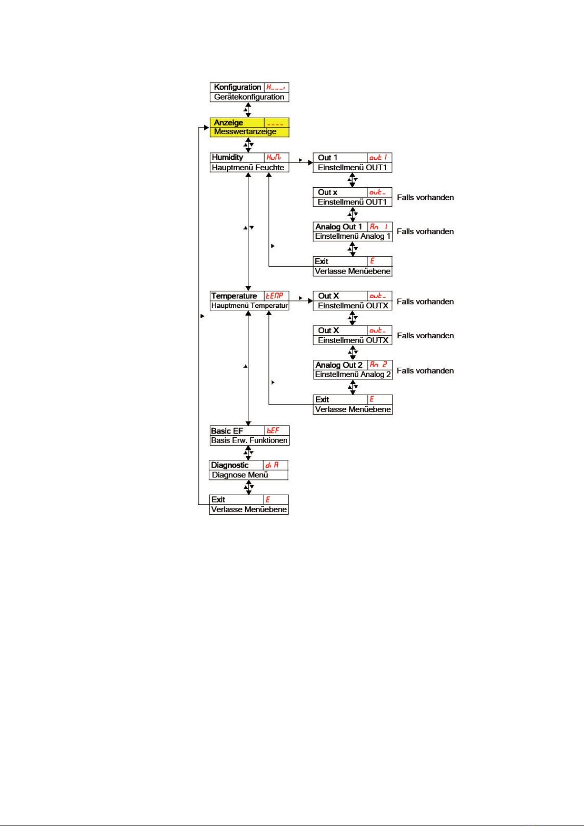
5.1.5 Menu overview
The structure of the menu is based on the VDMA standard sheet 24574-1.
The menu has a hierarchical structure. The top menu level contains the main menu
items, e.g. hUMi, TeMp, B.ef, DIa, e. Each main menu contains further submenu
items.
The menu items can vary depending on the configuration of the device. Not all menu
items described in the following may apply to your device.
You can call up the configuration by pressing the pkey in the display mode. A 4-digit
code is displayed, e.g.
Here the 4 digits mean tsav:
t: Type h= humidity and temperature
measurement
2 or 4
s: Number of switching outputs 0 or 2
a: Number of analog outputs i=standard assembly
(tank installation)
v: Assembly type of the device r=remote installation
Operation 17/46
RE51550-B/04.2021, Hengst Filtration GmbH
The individual menu items do not appear if the optionis not available. Example:
If a=0, the menu items for setting the analog output are not available. You can then
skip the description of these items.
The structure of the main menus Humidity (hUMi) and Temperature (TeMp) is
identical. The settings for the switching outputs or the analog outputs (if available)
are made here.

18/46 Operation
Hengst Filtration GmbHHengst Filtration GmbH, RE51550-B/04.2021, RE51550-B/04.2021
The basic settings of the device can be changed. General settings are made in the
menu Basic settings Advanced functions (B.ef).
These settings should be made first, as they affect the displays and adjustment
options in the individual menus. Such settings are e.g. the units used and the
assignment of the switching outputs to filling level and temperature measurement.
The assignment of the analog outputs cannot be changed.
In addition, the menu Diagnostic (DIa) contains options for diagnosis.
A detailed representation of the entire menu structure can be found in the
original operating instructions at the end of this chapter.
5.1.6 Changing the basic settings
The generally valid basic settings are made in the menu Basic settings advanced
functions (B.ef). These settings affect the representation in the measured value
display as well as the adjustment options in the various main menus. The assignment
of the switching outputs can also be changed here.
▶ Press the qkey to enter the main menu.
▶ Select the menu item (B.ef) with the qand pkeys and open the menu with the
ukey.
NOTICE
Switching off the normal troubleshooting!
Switching off the normal troubleshooting and error assessment is the factory
setting and, under certain circumstances, it can lead to dangerous operating
states, hazards for operators or machines. Before using this option, check the
hazard potential within your process. Hengst Filtration GmbH is not liable for any
health or material damage that may occur as a result of this setting.
5.1.6.1 Restore factory settings (reset)
The Reset (Res) function can be used to restore the factory settings. All changes will
be lost. Since the limit values are also reset, it is essential to check the settings for
filling level and temperature.
The following options are available:
Condition as supplied:
No, the current settings
are retained
Condition as supplied:
Yes, the settings are reset
to the default settings made
at the factory.

Operation 19/46
RE51550-B/04.2021, Hengst Filtration GmbH
The factory settings are as follows:
Definitions:
spx / Rpx Switching point / switch-back point x
Dsx / DRxSwitch-on delay / switch-back delay for switching output x
axhI / axlO maximum and minimum measured value for the output
a.OUx Signal form of the analog output
OUx Switching characteristic of the switching output x
h.UNI / T.UNI Unit for humidity / temperature
R.OUx Assignment of the switching outputxto filling level or temperature monitoring
DIs Update rate of the display
lOC Key lock
sj.OU logged switching output
Dh.MM Delay for recording the minimum / maximum humidity
DT.MM Delay for recording the minimum / maximum temperature
Notice: In the case of customer-specific requirements, the default settings made
at the factory may deviate from the values listed here.
Version with 2 switching outputs:
Switching outputs Basic settings
spi / Rpi 80 % / 75 %eRR.
£
NO
Dsi / DRi / OUi 0 / 0 / hNO h.UNI -i- (%)
sp2 / Rp2 60 / 55 c T.UNI c
Ds2 / DR2 / OU2 0 / 0 / hNO R.OUi hUMi
R.OU2 TeMp
DIs fasT
lOC 000
Version with analog outputs:
Analog outputs
ai.hI / ai.lO / a.OUi 0 / 100 / Ii
a2.hI / a2.lO / a.OU2 0 / 100 / Ii
Diagnostic settings:
Diagnosis
sj.OU OUTi
Dh.MM 0.0
DT.MM 0.0

20/46 Operation
Hengst Filtration GmbHHengst Filtration GmbH, RE51550-B/04.2021, RE51550-B/04.2021
5.1.6.2 Switching off the normal troubleshooting
Here you can activate/deactivate the normal troubleshooting and error assessment.
The function Switching off troubleshooting (eRR.
£
) deactivates normal
troubleshooting and error assessment. Under certain circumstances this can lead to
dangers for operators and machines.
Normal troubleshooting is deactivated in the factory setting of the WGM.
The following options are available:
Deactivates the normal
troubleshooting.
(standard setting)
Activates the normal
troubleshooting
Important notice: If the measuring range is exceeded or sensor errors
occur, the measured value is frozen and all six LEDs in the status bar
flash. When the measured value is within the valid range again, the LEDs
stop flashing and the display is updated normally.
5.1.6.3 Defining the unit for humidity
Here the displayed unit symbol for the humidity is defined:
The following options are available:
Percent
5.1.6.4 Defining the unit for temperature
Here the displayed unit symbol for the temperature is defined:
The following options are available:
Degrees
Celsius
Degrees
Fahrenheit
Notice: The measured value conversion and the adjustment of the
measurement range take place automatically. Nevertheless, the
corresponding switching and switch-back points must be checked.
This manual suits for next models
2
Table of contents
Popular Accessories manuals by other brands


Lord MicroStrain
Lord MicroStrain 3DM-GX5-10 user manual

Pepperl+Fuchs
Pepperl+Fuchs U-P R4 Series manual

Joolz
Joolz Geo lower raincover instruction manual

Carefree of Colorado
Carefree of Colorado Eclipse Service manual

Makita
Makita DFJ210 instruction manual

Siemens
Siemens Wireless Room Sensor Solution user guide


