Henny Penny BCC/BCR-140 User manual

TECHNICAL MANUAL
Henny Penny
Blast Chiller/Freezer
Models BCC/BCR-140
Models BCC/BCR-175
Models BFR/BCR-350


Model BCC/BCR-140, BCC/BCR-175, BFR/BCR-350
TABLEOFCONTENTS
Section Page
Section 1. TROUBLESHOOTING...........................................................................................................1-1
1-1. Introduction ..................................................................................................................1-1
1-2. Safety...........................................................................................................................1-1
1-3. Troubleshooting ............................................................................................................1-1
1-4. Alarm Messages..........................................................................................................1-5
Section 2. WIRING DIAGRAMS.............................................................................................................2-1
Section 3. PARTS INFORMATION .........................................................................................................3-1
3-1. Introduction ..................................................................................................................3-1
3-2. Genuine Parts ..............................................................................................................3-1
3-3. How to Order Parts .....................................................................................................3-1
3-4. Prices ...........................................................................................................................3-1
3-5. Delivery .......................................................................................................................3-1
3-6. Warranty ......................................................................................................................3-1
3-7. Recommended Spare Parts for Distributors................................................................3-1
FM06-024
Revised02-13-07
206 i


Model BCC/BCR-140, BCC/BCR-175, BFR/BCR-350
Thissectionprovidestroubleshootinginformationintheform
ofan easy-to-readtable.
Ifaproblemoccursduringthefirst operation of a cabinet,
rechecktheinstallationpertheInstallationSectionoftheOperator’s
Manual.
Beforetroubleshooting,alwaysrechecktheoperationproceduresin
theOperator’smanual.
603 1-1
1-1. INTRODUCTION
1-3. TROUBLESHOOTING Toisolateamalfunction,proceedasfollows:
1. Clearly define the problem or symptom and when it occurs.
2. Locate the problem inthetroubleshootingtable.
3. Review all possible causes. Then, oneatatimeworkthrough
thelistofcorrectionsuntilproblem issolved.
Ifmaintenanceproceduresarenotfollowed correctly,
injuriesand/orpropertydamagecouldresult.
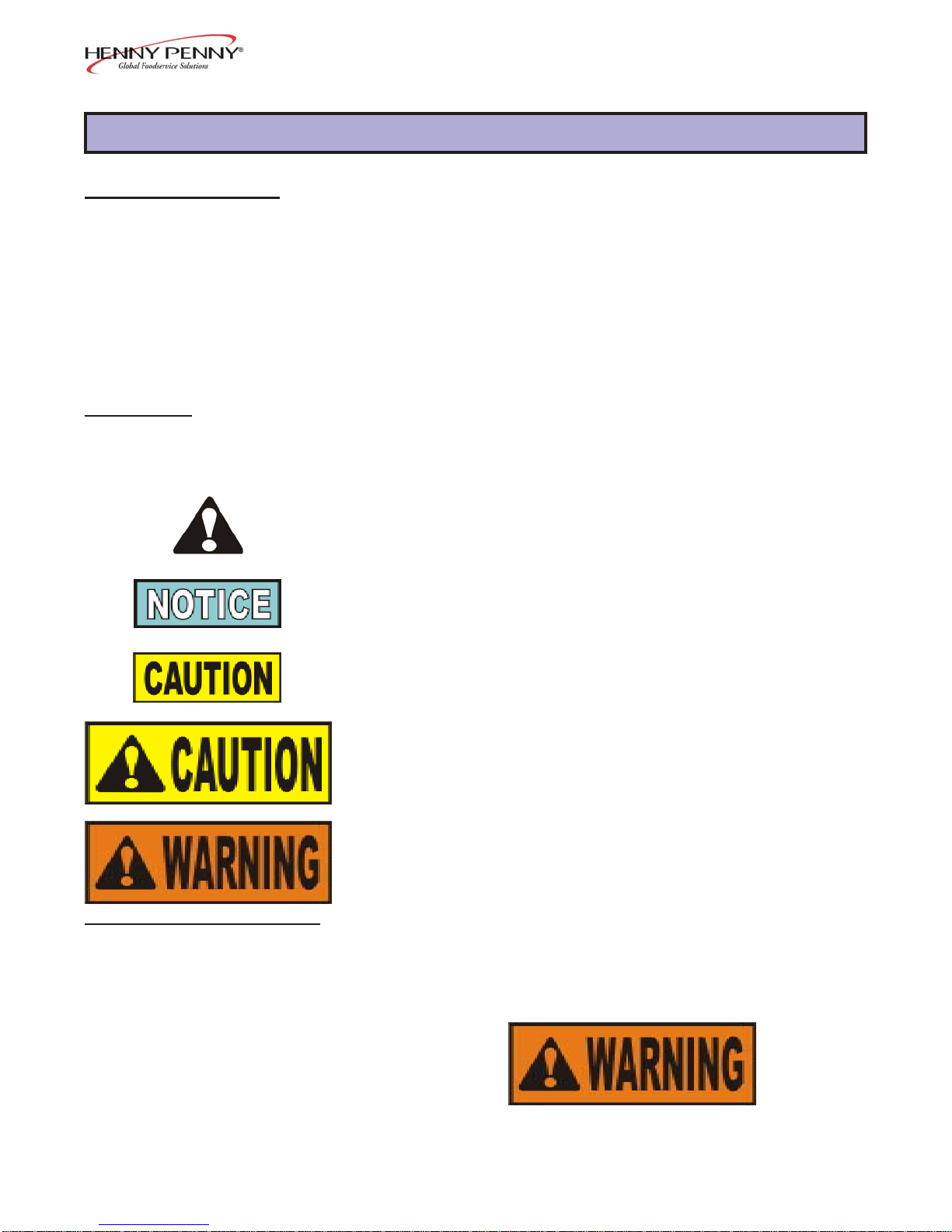
1-2. SAFETY Whereinformationisofparticular importanceorissafety
related, the words NOTICE, CAUTION, or WARNING are
used.Theirusageisdescribedbelow.
SAFETYALERTSYMBOLisusedwithDANGER,
WARNING, orCAUTION which indicates apersonal
injurytypehazard.
NOTICEisusedtohighlightespeciallyimportant
information.
CAUTION used without the safety alert symbol indicates
a potentially hazardous situation which, if not avoided,
may result in property damage.
CAUTION used with the safety alert symbol indicates a
potentially hazardous situation which, if not avoided,
may result in minor or moderate injury.
WARNINGindicatesapotentiallyhazardoussituation
which,if notavoided, couldresult indeath orserious
injury.
SECTION1.TROUBLESHOOTING

Model BCC/BCR-140, BCC/BCR-175, BFR/BCR-350
1-3. TROUBLESHOOTING
(Continued)
Problem Cause Correction
Theevaporatoris iced-up Faultyde-icingheater Replacede-icingheater
afteraDe-icingCycle Evaporatortemperatureatend Increasethe setting of step8,in
ofDe-icingCycletoolow ProgrammingSectionof
Operator’s Manual
MaximumtimeofDe-icingCycle Increasethesettingofstep7,in
tooshort ProgrammingSectionof
Operator’s Manual
Too much wateron evaporator The unithasbeenshutdownwithout StartaDe-icingCycle
fins a De-icingCycle
Slowto decrease Compressornotworkingproperly Check compressor and re-
intemperature(declinein placeifnecessary
performance) Evaporatorfannotworkingproperly Checkthefanandreplaceif
necessary
Temperatureofroomtoohigh Ventilatetheroom
Notenoughclearancearoundunit Relocatetheunit; seeLocation
Section of the Operator’s
Manual
1-2 603

Model BCC/BCR-140, BCC/BCR-175, BFR/BCR-350
1-3. TROUBLESHOOTING
(Continued)
Problem Cause Correction
Slowto decrease Condenserobstructedby dirt Cleanthecondenser
intemperature(declinein
performance) Evaporatoricedup PerformaDe-icingCycle
Refrigeratingproblem Checkrefrigerationcircuitand
components
Displaytemperaturedoes InFrigiprobeMode,thedisplay Normal
notmatchtheactualinletair shows the product temperature
temperature(Noalarm) Intimermode,or hold mode, Ohm out the probe and check
theprobemaybeshowingthe thereadingwiththetablelocated
wrongtemperature inthissection; change the probe
ifitisoutoftolerance
Greencompressorindicator Compressorandcondenserfan
lightonandthecompressor donotwork:
notworking,orworking -Faultycontactor Checkcontactorandchangeif
sometimes necessary
-Faultycontrol board relay-no Replace controlboard
voltageacrossterminals 10-11
Compressorworks, but condenser
fandoesnot:
-Faultycondenserfan Replacefan
Compressorandcondenser fan
worktogether:
-Faultyprotectioncomponent Checkitemsandreplaceif
for the compressor(overload necessary
protector,potential relay,start
and run capacitor)
-Faultyoverload protector of Check fanandreplace if
condenser fan necessary
603 1-3

Model BCC/BCR-140, BCC/BCR-175, BFR/BCR-350
1-3. TROUBLESHOOTING
(Continued)
Problem Cause Correction
Greencompressorindicator Voltageacrossterminals10-11
lightoffandcompressor of control board:
isworking - Control board relay bad Replacecontrolboard
Novoltageacross terminals 10-11
ofcontrolboard:
-Faultycontactor Replacecontactor
Greenfanindicatorlight Voltageacrossterminals8-9 of
onandfan(s)notworking controlboard.
- Fan or capacitor bad Replacefanorits capacitor
-Fanthermo-switchtripped Allow the fan motor tocoolto
seeif the fancomes back on;
ifthe fan doesnot come back
on, oritkeeps tripping, re-
placethefan
Novoltageacross terminals 8-9
ofcontrolboard:
-Faultycontrolboard relay Replace control board
Allindicatorlightsoffand Checkelectrical supply Plugunitintoreceptacle,or
ON/OFFswitchwillnot resetwallcircuitbreaker
operate Fuseofcontrol board blown Change thefuse
Novoltagefromthecontrol Changethecontrolboard
boardtransformer
Connectorbetweenthecontrol Checktheconnection
boardand display board not
connectedproperly
Badwireintheconnector between Replace the connector
thecontrolboardanddisplay
board
1-4 603

Model BCC/BCR-140, BCC/BCR-175, BFR/BCR-350
1-4. ALARM MESSAGES Intheeventofa systemfailure,thedigitaldisplaywillshowan
alarmmessage. Thesemessages are coded; “AL1”,“AL-2”,
“AL-3”,“AL-5”, and “AL-6.” When analarm occurs, thered
alarmLEDwillilluminateandabuzzer(optional)willsound.Press
theAlarmbutton to stop the buzzer.
Theunit can operate onauto back-up ifan alarm soundsfor a
faultyprobe. Mustselect theTimer Mode, andentera time.
Display Cause Correction
“AL-1” Faultyairtemperature Replacetheprobe; unit can operate on auto
probe back-upuntilanewprobeisinstalled
“AL-2” Faultyevaporatorprobe Replace the probe; the de-icing cyclecan operate at
50%ofthesettinginstep7oftheProgrammingSection
“AL-3” FaultyFrigiprobe Replacetheprobe; theFrigiprobeMode will not
operate,buttheunitwilloperateintheTimerMode
“AL-5” Temperaturetoolow Faulty control board- replace controlboard;
intheholdmode faultycontactor-replacecontactor
“AL-6” Temperaturetoohighin Faultycontrolboard-replace control board;
theholdmode door opened too much - make sure door stays
closedasmuchas possible
603 1-5

Model BCC/BCR-140, BCC/BCR-175, BFR/BCR-350
1-6 603

Model BCC/BCR-140, BCC/BCR-175, BFR/BCR-350
SECTION 2. WIRING DIAGRAMS
Wiring diagrams applicable to the blast chillers andblastfreezersareprovidedonthefollowingpages. Also,
twopagesareprovidedafterthewiringdiagramswhichlisttheservicereplacementpartsavailableforthe
variousmodelsoftheHennyPennyblastchillers and blastfreezers.
603 2-7

Model BCC/BCR-140, BCC/BCR-175, BFR/BCR-350
2-8 603

Model BCC/BCR-140, BCC/BCR-175, BFR/BCR-350
603 2-9

Model BCC/BCR-140, BCC/BCR-175, BFR/BCR-350
2-10 305

Model BCC/BCR-140, BCC/BCR-175, BFR/BCR-350
305 2-11

Model BCC/BCR-140, BCC/BCR-175, BFR/BCR-350
2-12 305

Model BCC/BCR-140, BCC/BCR-175, BFR/BCR-350
207 2-13
LIMITED WARRANTY FOR HENNY PENNY EQUIPMENT
Subject to the following conditions, Henny Penny Corporation makes the following limited warranties to the original
purchaser only for Henny Penny appliances and replacement parts:
NEW EQUIPMENT: Any part of a new appliance, except baskets, lamps, and fuses, which proves to be defective in
material or workmanship within two (2) years from date of original installation, will be repaired or replaced without
charge F.O.B. factory, Eaton, Ohio, or F.O.B. authorized distributor. Baskets will be repaired or replaced for ninety (90)
days from date of original installation. Lamps and fuses are not covered under this Limited Warranty. To validate this
warranty, the registration card for the appliance must be mailed to Henny Penny within ten (10) days after installation.
FILTER SYSTEM: Failure of any parts within a fryer filter system caused by the use of the non-OEM filters or
other unapproved filters is not covered under this Limited Warranty.
REPLACEMENTPARTS: Any appliance replacement part, except lamps and fuses, which proves to be defective in
material or workmanship within ninety (90) days from date of original installation will be repaired or replaced without
charge F.O.B. factory, Eaton, Ohio, or F.O.B. authorized distributor.
The warranty for new equipment covers the repair or replacement of the defective part and includes labor charges and
maximum mileage charges of 200 miles round trip for a period of one (1) year from the date of original installation.
The warranty for replacement parts covers only the repair or replacement of the defective part and does not include any
labor charges for the removal and installation of any parts, travel, or other expenses incidental to the repair or replacement of
a part.
EXTENDED FRYPOT WARRANTY: Henny Penny will replace any frypot that fails due to manufacturing or workmanship
issues for a period of up to seven (7) years from date of manufacture. This warranty shall not cover any frypot that fails due to
any misuse or abuse, such as heating of the frypot without shortening.
0TO3YEARS: During this time, any frypot that fails due to manufacturing or workmanship issues will
be replaced at no charge for parts, labor, or freight. Henny Penny will either install a new frypot at no cost or
provide a new or reconditioned replacement fryer at no cost.
3TO7YEARS: During this time, any frypot that fails due to manufacturing or workmanship issues will
be replaced at no charge for the frypot only. Any freight charges and labor costs to install the new frypot as
well as the cost of any other parts replaced, such as insulation, thermal sensors, high limits, fittings, and
hardware, will be the responsibility of the owner.
Any claim must be presented to either Henny Penny or the distributor from whom the appliance was purchased. No
allowance will be granted for repairs made by anyone else without Henny Penny’s written consent. If damage occurs during
shipping, notify the sender at once so that a claim may be filed.
THEABOVELIMITEDWARRANTYSETSFORTHTHESOLEREMEDYAGAINSTHENNYPENNYFORANYBREACH
OFWARRANTYOROTHERTERM. BUYERAGREESTHATNOOTHERREMEDY(INCLUDING CLAIMSFORANYINCI-
DENTALORCONSEQUENTIALDAMAGES)SHALLBEAVAILABLE.
The above limited warranty does not apply (a) to damage resulting from accident, alteration, misuse, or abuse; (b) if the
equipment’s serial number is removed or defaced; or (c) for lamps and fuses. THEABOVE LIMITED WARRANTY IS EX-
PRESSLYINLIEUOFALLOTHERWARRANTIES,EXPRESS ORIMPLIED,INCLUDING MERCHANTABILITYANDFIT-
NESS,ANDALLOTHERWARRANTIESAREEXCLUDED. HENNYPENNYNEITHERASSUMESNORAUTHORIZESANY
PERSONTOASSUMEFOR ITANYOTHER OBLIGATION ORLIABILITY. Revised 01/01/07

Model BCC/BCR-140, BCC/BCR-175, BFR/BCR-350
SECTION3. PARTS INFORMATION
3-1. INTRODUCTION Thissectionidentifiesandliststhereplaceablepartsofthe
HennyPennyblastchiller/freezer.
3-2. GENUINEPARTS UseonlygenuineHennyPennypartsinyourcabinet. Usinga
partoflesserqualityorsubstitutedesignmay result incabinet
damageorpersonalinjury.
3-3. HOWTO ORDER PARTS Once thepart you want to order has been found inthe Parts
List,writedownthefollowinginformation:
1. From the PartsList
(Sample)
ItemNumber 13
PartNumber 9501.6267
Description Condenser
2. From the dataplate
(Sample)
Product Number BCF.100
Serial Number 0001
Voltage 208V
3-4. PRICES Yourdistributorhasapricepartslistandwillbegladtoinformyou
ofthe costof yourparts order.
3-5. DELIVERYCommonlyreplaceditemsarestockedbyyourdistributor
andwill be sentout when your order is received. Other parts
willbeorderedbyyourdistributorfromHenny Penny Corpora-
tion. Normally, these willbesenttoyourdistributorwithinthree
workingdays.
3-6. WARRANTY Allreplacement parts (except lamps andfuses)arecovered
underwarrantyfor90daysagainst manufacturingdefects
andworkmanship. Ifdamageoccursduringshipping,notify
thecarrierat once sothata claim maybeproperly filed. Refer
towarrantyonthefrontofthissectionforother rights and
limitations.
Recommendedreplacementparts,stockedby your distributor,are
indicated with √√
√√
√ intheparts lists. Please use carewhenordering
recommendedparts,becauseallvoltagesandvariationsare
marked. Distributorsshouldorder parts based upon common
voltagesandequipmentsoldin theirterritory.
3-1 206
3-7. RECOMMENDED
SPAREPARTSFOR
DISTRIBUTORS

Model BCC/BCR-140, BCC/BCR-175, BFR/BCR-350
Quantity BFR/
Item BCC BCR BCC BCR BCR
No. Part No. Description 140 140 175 175 350
√√
√√
√1 9504.0205 ControlPC Board 11111
√√
√√
√2 9503.3692 DisplayPCBoard 11111
√√
√√
√3 9503.3700 AuxiliaryDisplayBoard 11111
4 9503.3759 ConnectingCable 11111
√√
√√
√5 9503.7719 CommunicationBoard 11111
6 9503.8436 Printer 11111
7 9503.8428 PrinterConnectingCable 11111
√√
√√
√8 9503.3726 Buzzer - 240V - UL 11111
9 9500.7936 Drier 1 - 1 - -
√√
√√
√10 9503.6232 De-icingHeater - UL -500W 33336
√√
√√
√11 9500.7209 AirProbe 11111
√√
√√
√12 9500.7209 EvaporatorProbe 11111
√√
√√
√13 9502.6563 Run Capacitor - 4 mF 3333-
14 9560.0334 EvaporatorFan 33334
15 9505.3963 EvaporatorFan Grid - UL 33334
√√
√√
√16 9502.0400 Frigiprobe 11111
√
√
√√
√17 9503.3643 FuseHolder 11111
√√
√√
√18 9503.3650 Fuse - 10A 11111
√√
√√
√19 9503.0185 VaristorV320LA20A 11111
20 9503.3601 ControlPanelDecal 1111-
20 9503.6224 ControlPanel Decal - BCR-350 ----1
21 9501.5186 Contactor - UL/CSA - 3P 23A/AC3 - - 1 - 1
(BCC-175beforeOct.2004, order9502.0848 also)
21 9503.0912 Contactor - UL/CSA - 3P 12A/AC3 1 ----
22 9503.3304 Condenser Fan Motor-25W, 230V, 60 Hz - - 1 - -
22 9502.1846 Condenser Fan Motor-120W, 230V, 60 Hz 1 ----
23 9501.8644 Water Condenser - 115V - - 1 - -
24 9503.7784 Condenser - UL 1 ----
25 9503.3312 Fan Blade for Condenser - BCC-175 - - 1 - -
26 9503.6190 Compressor - BCC-175 - - 1 - -
26 9502.1762 Compressor - BCC-140 1 ----
27 9502.8668 Evaporator - BCC/BCR-175 - - 1 1 -
27 9501.6283 Evaporator - BCC/BCR-140 1 1 - - -
27 9502.8676 Evaporator - BCR-350 ----1
√√
√√
√28 9503.6174 ThermalOverloadRelay - BCC-175 - - 1 - -
√√
√√
√28 9503.6158 ThermalOverloadRelay - BCC-140 1 ----
√√
√√
√29 9503.6257 F. Frame Heater-BCC-175; BCR-175/350 - - 2 2 2
√√
√√
√29 9503.7735 FrontFrame Heater-75W-BCC/BCR-140 1 1 - - -
√√
√√
√30 9502.5995 ExpansionValve-BCC-175;BCR-175/350 - - 1 1 2
√√
√√
√30 9502.6951 ExpansionValve-BCC/BCR-140 1 1 - - -
√√
√√
√30 9502.5383 ExpansionValve-BFR-350 ----2
31 9500.8850 Nozzle-Exp.Valve-BCC-175; BCR-175/350 - - 1 1 2
31 9500.8843 Nozzle-ExpansionValve-BCC/BCR-140 1 1 - - -
√√
√√
√recommended parts
606 3-2

Model BCC/BCR-140, BCC/BCR-175, BFR/BCR-350
Quantity BFR/
Item Part BCC BCR BCC BCR BCR
No. No. Description 140 140 175 175 350
31 9500.8967 Nozzle-ExpansionValveBFR-350 ----2
32 9500.7993 Water Pressure Valve - BCC-175 - - 1 - -
√√
√√
√33 9503.6182 HighPressure Switch -BCC-140 1 ----
34 9502.5045 LiquidReceiver- BCC-140 1 ----
34 9550.4585 Door - BCC/BCR-175/350 - - 1 1 1
34 9550.6630 Door - BCC/BCR-140 1 1 - - -
35 9543.0831 FrontPanel for Printer - BCC/BCR-175 - - 1 1 -
35 9542.5989 FrontPanel for Printer - BCC/BCR-140 1 1 - - -
36 9541.6053 Vert.Evap.Deflector-BCC/BCR-175 - - 1 1 -
36 9541.7671 Vert.Evap.Deflector-BCR-350 ----1
37 9505.3674 Door Seal - BCC/BCR-175/350 - - 1 1 1
37 9505.4466 Door Seal - BCC/BCR-140 1 1 - - -
38 9501.9998 Floor Door Seal - BCC/BCR-175 - - 1 1 -
39 9541.8919 LeftandRight Side Panels- BCC/BCR-175 - - 2 2 -
40 9542.5963 LH Panel-BCC-140; LH & RH-BCR-140 1 2 - - -
41 9542.7225 RightSide Panel - BCC-140 1 ----
42 9543.0419 TopCoverwith Condensing Unit-BCC-140 1 ----
42 9543.0518 TopCover w/oCondensing Unit-BCR-140 - 1 - - -
42 9543.0427 TopCoverwith Condensing Unit-BCC-175 - - 1 - -
42 9543.0542 Top Cover w/o Cond.Unit-BCR-175/350 - - - 1 1
43 9502.8601 Door Latch - BCC/BCR-175; BCR-350 - - 1 1 1
43 9501.4551 DoorLatch with Strike - BCC/BCR-140 1 1 - - -
44 9502.8619 Door Strike - BCC/BCR-175; BCR-350 - - 1 1 1
45 9502.8585 Door Hinge - BCC/BCR-175; BCR-350 - - 2 2 1
45 9501.4601 DoorHinge - BCC/BCR-140 1 1 - - -
46 9502.8593 HingeShim - BCC/BCR-175;BCR-350 - - 2 2 1
√√
√√
√47 9503.6240 HighLimitSafetyThermostat 11112
48 9503.4583 ValveBody - BCR-140/175/350 - 1 - 1 1
49 9503.4591 Coil - BCR-140/175/350 - 1 - 1 1
√√
√√
√50 9504.0128 PowerSwitch 11111
51 03201 PrinterAccessory Bracket 11111
52 9504.0139 32MMPlasticDrain 11111
53 9500.2804 32MMPVC Elbow 11111
54 9503.9236 32MM PVC - T 11111
√√
√√
√recommended parts
3-3 806
Other manuals for BCC/BCR-140
1
This manual suits for next models
8
Table of contents
Other Henny Penny Freezer manuals
Popular Freezer manuals by other brands

VEDETTE
VEDETTE CS6282SI Instructions for installation and use

Vestfrost
Vestfrost CFS 344 Instructions for use and installation

Hotpoint
Hotpoint FZA34 Instructions for installation & use

Kenmore
Kenmore 23738 owner's manual

Siemens
Siemens GI25NP60 Instructions for use

montpellier
montpellier MS150W Installation and operating instructions