Henry Radio 3K Classic Mark II Operating instructions

Henry Radio
Linear Amplifiers
-----------------------------
Operating and Maintenance
Manual
-----------------------------
3K Classic Mark II
3K Classic X Mark II
5K Classic.
-
II
E
M
RY
REIDI
O
2050 S. BUNDY
DRIVE
LOS ANGELES, CA 90025 USA
(213) 820-1234
Telex: 67-3625 (Henradio)

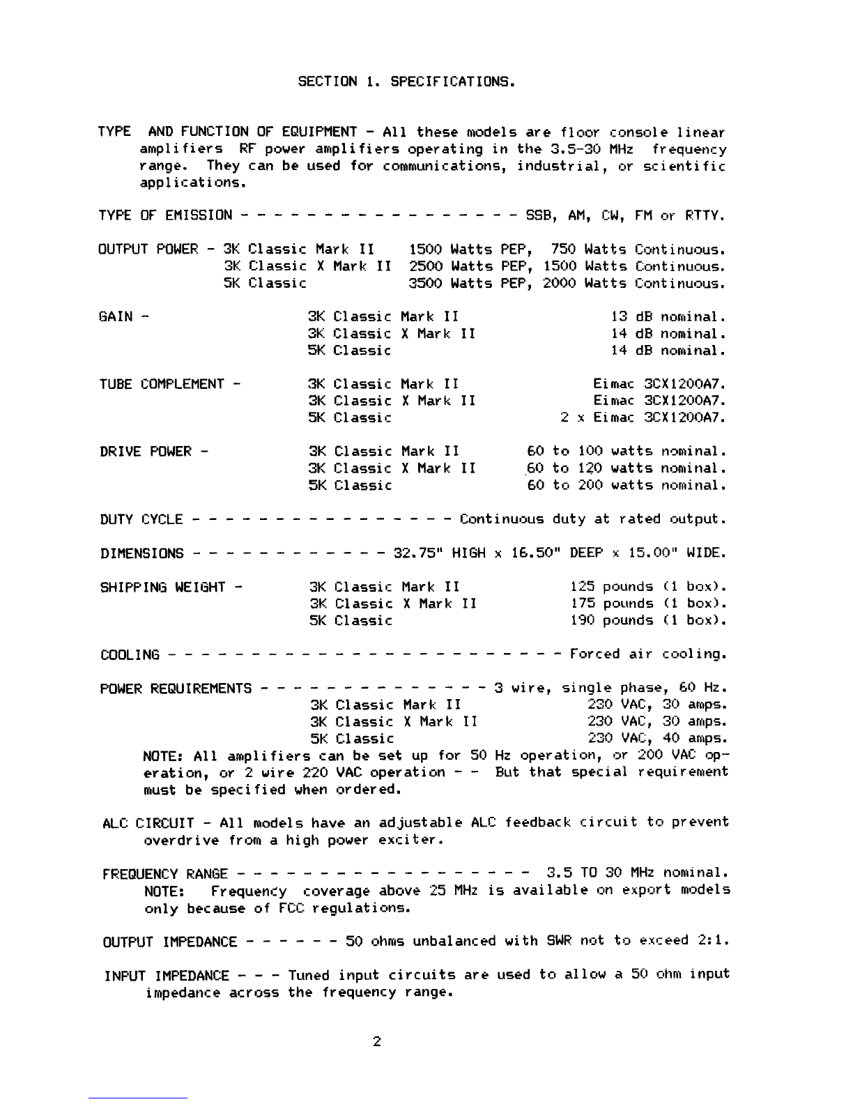
SECTION 1. SPECIFICATIONS.
TYPE
AND FUNCTION OF EQUIPMENT - All these models are floor console linear
amplifiers
RF power amplifiers operating in the 3.5-30 MHz frequency
range.
They can be used for communications, industrial, or scientific
applications.
TYPEDFEMISSION ----------------- SSB, AM, CW, FM or RTTY.
OUTPUT POWER
-
3K Classic Mark II
1540 Watts PEP, 750 Watts Continuous.
3K Cl
assic X Mark 11 2500 Watts PEP, 1500 Watts Continuous.
5K Classic
3500
Watts PEP, 2400 Watts Continuous.
GAIN -
3K Classic Mark II
13 dB nominal.
3K Classic X Mark II
14 dB nominal.
5K Classic
14 dB nominal.
TUBE COMPLEMENT -
3K Classic Mark
II
Eimac 3CX120nA7.
3K Classic X Mark II
Eimac 3CX124OA7.
5K Classic
2 x Eiroar 3CX1200A7.
DRIVE POWER - 3K Classic Mark II
60 to 104) watts nominal.
3K Classic X Mark II
60 to 120 watts nominal.
5K Classic 60 to 200 watts nominal.
DUTY
CYCLE - - - - - - -
- - - - - - - - - Continuous duty at rated output.
DIMENSIONS
- - - - - - - - - - - - 32.75" HIGH x 16.50" DEEP x 15.00" WIDE.
SHIPPING WEIGHT
-
3K Classic Mark II
125 pounds (1 box).
3K Classic X Mark
II
175
pounds
(
1
box).
5K Classic
190 pounds (1 box).
COOLING - - - - - - - - - - - - - - - - - - - - - - - - Forced air cooling.
POWER REQUIREMENTS
-
- - - - - - - - - - - - - 3 wire, single phase, 60 Hz.
3K Classic Mar
k 11
230 VAC,
30 amps.
3K Classic X Mark
II
230 VAC,
30 amps.
5K Classi
c
230
VAC, 40 amps.
NOTE: All amplifiers can be set up for 50 Hz operation,
or 200 VAC op--
eration,
or 2
wire
220 VAC
operation -- But that special requirement
must be specified when ordered.
ALC CIRCUIT -All models have an adjustable
ALC: feedback circuit to prevent
overdrive from a high power exciter.
FREQUENCY RANGE - - - - - - - - - - - - - - - - - - 3. 5 T0 30 MHz nominal.
NOTE:
Frequency
coverage
above 25 MHz is available on export
models
only because
of FCC
regulations.
OUTPUT IMPEDANCE ------ 50 ohms unbalanced with SWR not to exceed 2:1.
INPUT IMPEDANCE - - - Tuned input circuits are used to allow a 50 ohm input
impedance
across the frequency range.
2
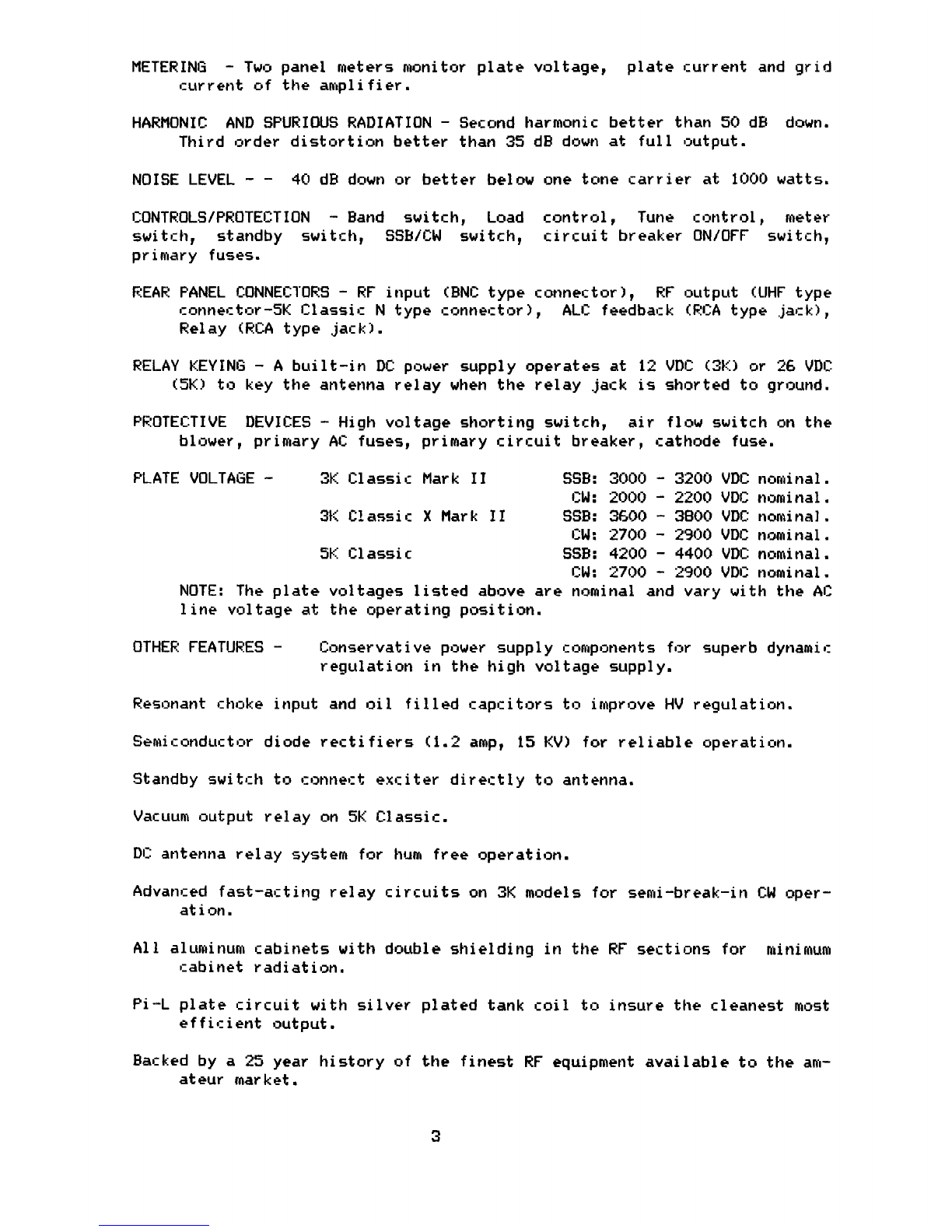
METERING - Two panel meters monitor plate voltage, plate current and grid
current of the amplifier.
HARMONIC
AND SPURIOUS RADIATION - Second harmonic better than 50 dB down.
Third order distortion better than 35 dB down at full output.
NOISE LEVEL - - 40 dB down or better below one tone carrier at 1000 watts.
CONTROLS/PROTECTION
- Band switch, Load control, Tune control, meter
switch,
standby
switch,
SSB/CW
switch,
circuit breaker ON/OFF switch,
primary fuses.
REAR PANEL CONNECTORS - RF input (BNO type connector), RF output (UHF type
connector-5K Classic N type connector),
ALC feedback (RCA type .jack),
Relay (RCA type jack).
RELAY KEYING
- A built-in
DC power
supply operates
at 12 VDC (3F-'.) or 26 VDC
(5K) to key
the antenna relay when the relay jack is shorted to ground.
PROTECTIVE
DEVICES - High voltage shorting switch, air flow switch on the
blower, primary AC fuses, primary circuit breaker, cathode fuse.
PLATE VOLTAGE
-
3K Classic Mark II
558:
3000 - 3200 VDC
nominal.
CW: 2000 - 22170 VDC nominal.
31;
Classic X Mark II
58B:
3600
- 3800 VDC nominal.
CW: 2700 - 25oO
VDC nominal.
5K Classi
c
SSB: 4200
- 4400
VDC nominal.
CW: 2700 - 2900
VDC nominal.
NOTE: The plate
voltages listed above are nominal and
vary
with the AC
line voltage at the operating position.
OTHER FEATURES -
Conservative power supply components for superb dynamic
regulation in the high voltage supply.
Resonant choke input and oil filled rapritors to improve HV regulation.
Semiconductor diode rectifiers (1.2 amp, 15 KV) for reliable operation.
Standby switch to connect exciter directly to antenna.
Vacuum output relay on 5K Classic.
DC antenna relay system for hum free operation.
Advanced fast-acting relay circuits on 3K models for semi-break-in CW oper-
ation.
All aluminum cabinets with double shielding in the RF sections for minimum
cabinet radiation.
Pi--L plate circuit with silver plated tank coil to insure the cleanest most
efficient output.
Backed by a 25 year history of the finest RF equipment available to the am-
ateur market.
3
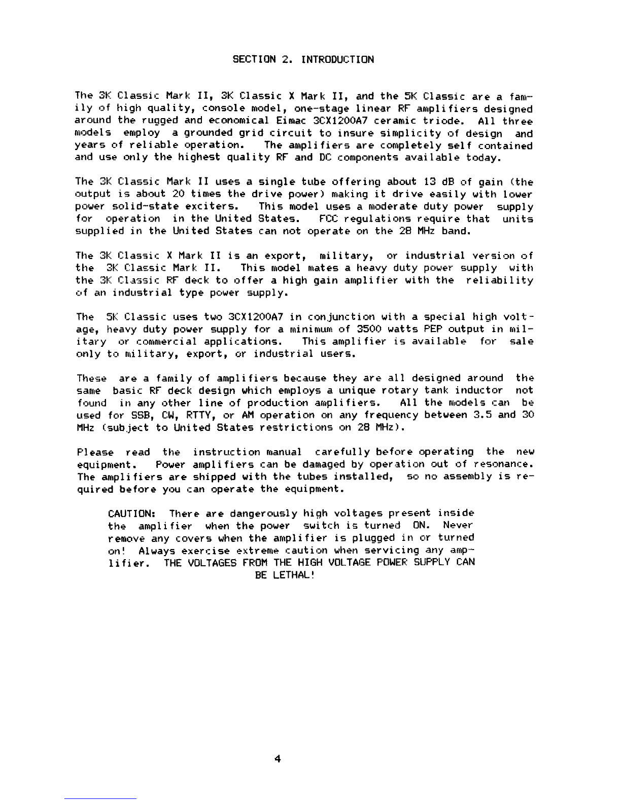
SECTION 2. INTRODUCTION
The 3K Classic Mark
II,
3K
Classic X Mark II, and the 5K. Classic are a fam-
ily of
high quality, console model, one-stage linear RF amplifiers designed
around the rugged and economical Eimac
3CX1200A7
ceramic
triode.
All three
models
employ
a grounded grid circuit to insure simplicity of design and
years of reliable operation.
The amplifiers are completely self contained
and use only the highest quality RF and DC
c
omponents available today.
The 3F;
Classic Mark II uses a single tube offering about 13 dB of gain (the
output is about 20 times the drive power) making it drive easily with lower
power solid-state exciters.
This model uses a moderate duty power supply
for
operation in the United States.
FCC regulations require that units
supplied in the United States can not operate on the 28 MHz band.
The 3f; Classic X Mark II is an export, military, or industrial version of
the
3K Classii. Mark II.
This model mates a heavy duty power-, supply with
the ';k: Classic RF deck to coffer a high gain amplifier with the reliability
of an industrial type power supply.
The
5K Classic
uses two
3CX120OA7
in conjunction with a special
high v-31t--
age,
heavy
duty power supply for a minimum
of 3500
watts PEP output in mil-
itary
or
commercial applications.
This
amplifier is available for sale
only
to military, export, or industrial users.
These
are a family of amplifiers because they are all designed around the
same
basic RF deck design which employs a unique rotary tank inductor not
found
in any other line of production amplifiers.
All the models can be
used for SSB, CW, RTTY,
or AM operation on any frequency between 3.5 and 30
MHz (subject to United States restrictions on 28 MHz).
Please read the instruction manual carefully before operating the new
equipment.
Power amplifiers can be damagedby operation out of
resonance.
The amplifiers are shipped with the tubes installed,
sr, no
assembly is re-
quired before you can operate the equipment.
CAUTION:
There
are dangerously high voltages present inside
the
amplifier
when the power switch is turned
ON.
Never
remove any covers
when the amplifier is plugged
in or turned
on!
Always exercise
extreme
caution
when
servicing
any amp-
lifier.
THE VOLTAGES FROM THE HIGH VOLTAGE POWER SUPPLY CAN
BE LETHAL!
4

SECTION 3. INSTALLATION
SECTION
3.1
UNPACKING
When
you first receive the ahplifitr you must carefully inspect first tQ.
box and then the amplifier for any sign of damage during shipment.
If you
see
any
shipping damage,
save the box and packing material and notify ?.h:^
transportation company immediately.
It is a good idea to save the box and
packing
material in any case nr.::aur-.r they are expensive to replace and
arc-
useful
in protecting the amplifier should you ever decide to ship it or
move it to another location.
Remove the amplifier from Its shipping carton and packing material.
your
unit is packed into a':aingle carton and is ready to operate with the e-xc*p-'-
tion of a power plug. A power plug that mates with the power socket at the
operating location must be properly installed as described in section
3.33
before the unit can be operate.:.
The following accessories should be included with the amplifier.
1
Instruction Manual
I
Warranty Card
1
PL259 Coax Connector QF,7
1
Drive Cable (RG58)
J.
N type Coax Connector i50
1
Set Fuses
2
Shielded Control Cables
SECTION 3.2 OPERATING LOCATION
The
amplifier
may
be located wherever desired provided there is adequate
air
flow from the bottom of the unit up through the top of the amplifier.
Do not restrict the airflow
o
f
the amplifier,
and never place it too close
to a wall that might
restrict the
airflow into the hack: of the unit.
You
will require a location
that
has an appropriate 220 VAC power source. A
location
which avoids environmental extremes of heat, humidity, and dust
will keep the amp]
i
fisrr new looking and assure
years
of reliable operation.
SECTION 3.3 CABLING
All
of
the
following cables must be connected before operation
of
the
amplifier.
POWER CABLE
-
"
The
amplifier is equipped with a 3-wire AC power
cable that
is normally wired to accept 220 VAC, 3 wire, 60 Hz, single phase power .an-
-less
special instructions were given at the time of the order.
A factory
modification is required
for 50
Hz operation,
or 200
VAC olreration,
or for
2--
wire cur opean operation.
The three wires in the power 16t?le are black, white, and green. The green
wire is chassis ground and the neutral on the 220 VAC plug.
The black and
white wires connect the "hot" 220 VAC circuits.
A power plug is not sup--
plied
becau5e there are many different types of 220 VAC outlets.
We sug-
gest that you consult with a local electrician about the proper :oril?ectlor1
5

of your plug type.
CAUTION: The
amplifier
will be damaged if the green
wire is connected to the 220 VAC terminal. Make sure
that the green is connected to the neutral terminal.
ANTENNA
COAX - Use only RG-8/U coax (or better) to connect the amplifier
to the antenna or dummy load.A PL-259 (UHF type) coax connector is in-
cluded in the accessory kit.
Prepare the cable and connector as described
in
Figure 1 below.
The PL-259 mates with the coax jack marked OUTPUT on
the rear panel of the amplifier.
The 5K. Classic uses an N type connector
which is supplied in the accessory kit.
CAUTION:
Never operate the amplifier unless it -_on-
nected to an antenna or a dummy load capable of hand-
the output of the unit. You will damage the equip-
ment if you operate it without a load or into a load
with
an SWR greater than 2:1 (a reflected power more
than 10% of the forward power). Measure the antenna's
SWR with an SWR meter, using only the exciter output,
before operating the amplifier.
With the amplifier in
the off position, the exciter output will pass through
the amplifier directly to the antenna.
DRIVE
CABLE
- The R8-58/U drive cable supplied in the accessory kit con-
nects to the INPUT connector on the rear panel of the amplifier. This con-
nector is a BNC type coax connector. The UHF connector on the other end of
the cable must be connected to the f2F output connector of the exciter.
An
adapter may be required if the exciter does not have a matching connector.
ALC (Automatic Level Control) CABLE - Plug the gray ALC cable into the ALC
OUT
phono socket on the rear panel of the amplifier and into the ALC feed-
back connection on the exciter. If the exciter does not have provision for
feedback of ALC voltage from the amplifier, no connection is necessary.
RELAY
CABLE - The gray relay control table must be plugged into the phano
plug marked RELAY on the bark panel of the amplifier.
This cable conducts
the keying signal from the exciter to switch the amplifier to the transmit
condition
and must be connected to the socket or connector marked antenna
relay (or its equivalent) on the exciter. The exciter needs to supply only
a shorting relay contact (closed to ground during transmit) to key the amp.
CAUTION:
Never
apply any voltage to the relay jack of
the
amplifier!
Your amplifier has a built-in power
supply which provides the necessary voltage.
Most
modern transmitters or transceivers make easy provision for a relay
control connection.
If the connection is not obvious to you, examine the
operating
manual of'the exciter to find an available unused relay contact
that is normally closed during transmit.
Some
modern transceivers use diode switching rather than relay switching.
Henry amplifiers use 12 VDC (or 26 VDC) relay control voltage, any resis-
tance across the relay control line may keep the amplifier from keying. If
your
exciter will not key the amplifier, you should check the resistance
6

J ^(,:L 1
A".;5kMt::- 'F i4rYi:11_IF:
C 'QA:
O
i1dNE=1= i OF'.
f
coupling ring
jiugs 83•15P, 83-822
_
_
. ^.
. _..... _..
^.. _.. _ _.. _.... . . _..^
Cut end of cable
even. Remove
vinyl jacket 1',
except 83-ISP
plug remove vinyl jacket 114'".
Bare '•;
of center conductor. Trim braided shield Shot LIJUP1111g
ring on cable Tin exposed
center conductor
and braid
Srrew the pi-if: sub
on :,rt;,e: ^Noiorr a.^Nnt,!y ti, i::d:r:
through solder holes
mak!n); a
;
:,ud
bond between
Win arid
shell
SuIder rwidur'.,r
to. rnrt;:'
,h;
nut ul.i ex:,:s..:•.:
he
n
.
^.•.
_,
rltf111tf11^^
ME
For final assembly, screw coupling ring on plug sub
assembly.
-7

across the contact you are using. If there is too much resistance, contact
the exciter's manufacturer about possible solutions to the problem.
SECTION 3.4 TRANSFORMER TAPS
The
amplifier is normally factory wired for
22(]-230
VAC,
3 wire,
60
Hz
operation unless specially ordered otherwise. If the AC mains are differ-
ent then you will probably have to make a modification in the power supply.
5o
HZ OPERATION - Unlike most other amplifiers on the market, most Henry
amplifiers use a resonant filter choke.The choke is factory resonated at
60
Hz unless otherwise specified.
For 50 Hz operation a third resonating
capacitor must be added.
This will be done at the factory if specified at
the time of order.
FILAMENT
TRANSFORMER
-
The filament transformer is marked
EE'A 1226 (3!!
Classic)
or
ECA 1194 (
5K Classic).
They are factory
tapped for
230
VAC
operation.
If
the
AC line voltage is significantly different,
YOU must
rewire
the taps on
the transformer
(
located in the power supply section).
E. CA 1 222 b
Tap 1
-
Common----
Tap t - 200 VAC ---
Tap 3 -2
10 VAC ---
Tap 4
- 220 VAC----
Tap 5 - 230 VAC---
ECA 1194
Tap 1
- Common---
Tap 2 - ^00 VAC---
Tap 3
- 210 VAC----
Tap 4 - 220 VAC---
Tap 5 - 230 VAC---
Tap 6 - 240 VAC---
NOTE:
The nominal filament voltage at the tube is
7.5 VAC.
The amplifier
does
not meter filament voltage,
so you must use an external Al:: voltmeter
to
measure the filament voltage at pin jacks on the back panel of the RF
chassis.
The 3K Classic should measure close to 7.8 VAC at the pin jacks.
The 5K
Classic
filaments
are in series and the voltage should read about
15.6 VAC.
becaf the voltage varies more than 5% from these figures, the
taps on the filament transformer should be changed.
HIGH
VOLTAGE TRANSFORMER- The 3K C
lassic Mark I I domestic amplifier is
supplied with the ECA 1120A. The primary tap connections are listed below:
ECA 1120A
--------------------------------
230 VAC --------------Tap 1
;
---.-.-Tap 3
: ----.--Tap 5
230 VAC---------------Tap 7
The 3K Classic X and 5K Classic are supplied with
one of
the following high
voltage transformers:
8
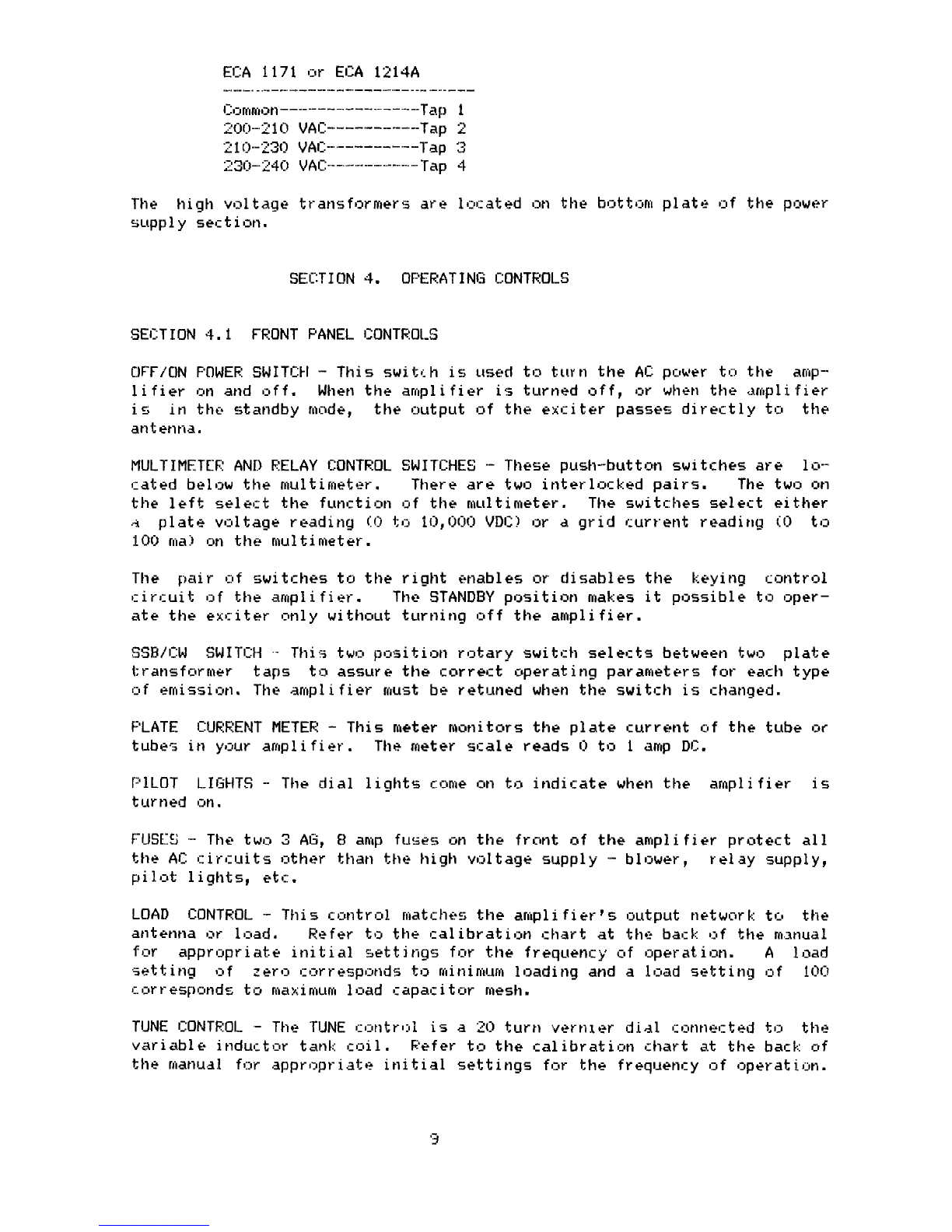
Ei_A 1171 or
ECA 1214A
Common---------------------Tap 1
200-21 0 VAC -------------Tap 2
210-230 VAi=---------- Tap 3
230-^^240 VAI.---------- -fap 4
The
high voltage transformers are located on the bottom plate of the power
supply section.
SECTION 4.
OPERATING CONTROLS
SECTION 4.1
FRONT PANEL CONTROLS
OFF/ON POWER SWITCH - This switch is used to turn the Al; power to the amp--
lifier on and off. When the amplifier is turned off, or when the amplifier
is in the standby mode, the output of the exciter passes directly to the
antenna.
MULTIMF:.TEF' AND RELAY CONTROL SWITCHES - These push-button switches are lo---
cated below the multimeter.
There are two interlocked pairs.
The two on
the left select the function of the multimeter. The switches select either
:x
plate voltage reading (0 to 10,000 VDi.? or a grid current reading (0 to
:L00 ma) on the multimeter.
The pair of switches to the right enables or disables the keying control
circuit of the amplifier.
The STANDBY position makes it possible to oper-
ate the exciter only without turning off the amplifier.
SSl3/i:W
SWITCH - This two position rotary switch selects between two plate
transformer
taps to assure the correct operating parameters for each type
of emission. The amplifier must be retuned when the switch is changed.
PLATE
CURRENT METER - This meter monitors the plate current of the tube or
tubes in your amplifier. The meter scale reads i) to 1 amp DC.
P1LOT
LIGHTS --
The dial lights come on to indicate when the amplifier is
turned on.
FUSES -•- The two 3 AG, E3 amp fuses on the front of the amplifier protect all
the AC circuits other than the high voltage supply - blower, relay supply,
pilot lights, etc.
LOAD
GONTROL_ -- This cr,ntrol matches the amplifier's output network: to the
antenna or load.
Refer to the calibration chart at the back of the manual
for
appropriate initial settings for the frequency of operation.
A
load
setting
of
zero corresponds to minimum loading and a load setting of 100
corresponds to maximum load capacitor mesh.
TUNE CONTR01..
-
The TUNE control is a2r? turn vernier dial connected to the
variable inductor tanL:: coil.
Refer to the calibration chart at the back of
the manual for appropriate initial settings
for the
frequency of operation.
.3
. ^^..:^
.
,_.
...
CONTROLS.
%
19
16
20
IN
_n
23
17
18
14 15
0
@
® 0 ®
EH
22
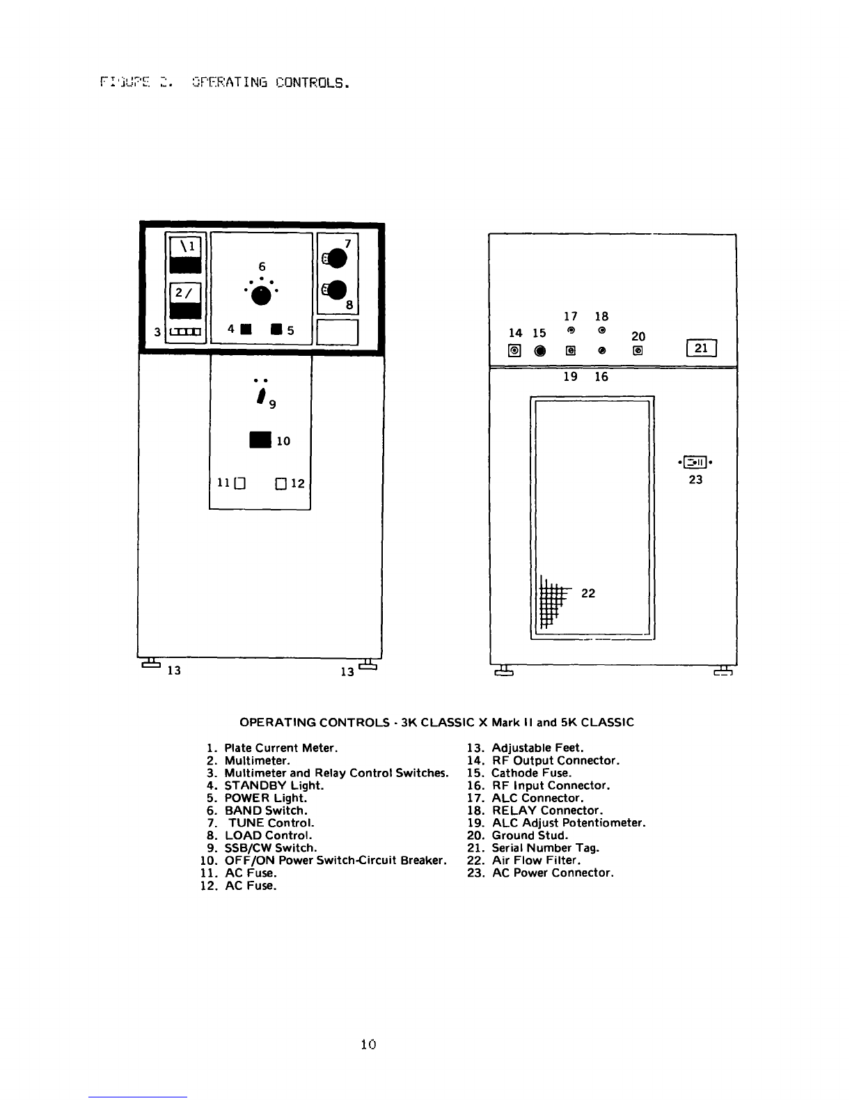
OPERATING CONTROLS - 3K CLASSIC
X Mark 11
and 5K CLASSIC
1.
Plate Current Meter.
2.
Multimeter.
3.
Multimeter and Relay Control Switches.
4. STANDBY Light.
5.
POWER Light.
6.
BAND Switch.
7.
TUNE Control.
8.
LOAD Control.
9.
SSB/CW Switch.
10.
OFF/ON
Power
Switch-Circuit
Breaker.
11.
AC Fuse.
12.
AC Fuse.
13.
Adjustable Feet.
14. RF Output Connector.
15. Cathode Fuse.
16. RF Input Connector.
17.
ALC Connector.
18. RELAY Connector.
19.
ALC Adjust Potentiometer.
20. Ground Stud.
21. Serial Number Tag.
22. Air Flow Filter.
23. AC Power Connector.
10

BAND
SWITCH -- The BAND switch selects the
correct
tuned input circuit and
the appropriate capacitance on the output circuit for the frequency of op--
oration.
Listed below are guidelines for the band position relative to op---
orating frequency.
NEVER move the BAND switch when the amplifier is keyed.
BAND
80 ....
........... 3.5 TO 5
MHZ
OPERATING FRE
QUENCY
40
5 TO 10 MHZ
----
--------
---
------
20 ............... 10 TO 17 MHZ
(Approximate)
15 ............... 17 TO 24 MHZ
10 ............... 24 T0 30 MH7-
------------------------------------------------------------------
SECT I OPJ 4.2
REAR PANEL CONTROLS AND CONNECTIONS
AU::
JACK - This socket accepts an RCA pFiono plug (an AU:: cable is pro•-
vided in the accessory kit) to connect a feedback: voltage from the
ampli...-
fi.er to the exciter.
No connection is necessary if the exciter does not
have provisions for ALC feedback.
ALC
ADJUSTMENT POTENTIOMETER -- This potentiometer controls the sensitivity
of the amplifier's AU: feedback circuit. See the operating section for in--
structions on how to adjust the ALC circuit.
RELAY
CONTROL JACK - The RCA j
ack marked
RELAY CONTROL connects the
ampli--
fier to the exciter to key the
amplifier when the
exciter is
transmitting.
A interconnection cable is s
upplied in
the accessory
kit.
When the socket
is shorted
to ground,
the amplifier's antenna relay closes. If the ampli-
fier-
is turned off, or in the STANDBY
mode,
the relay can
not be keyed.
Never
apply any voltage to this socket.
RF INPUT CONNECTOR
°-
This
BNC coax connector accepts the drive line from
the exciter.
The input impedance of the amplifier is nominally 50 ohms.
F:f-
OUTPUT i.CJNNECTOf='.. - The nominal output of the amplifier is 50 ohms.
Do
not
operate the amplifier unless an antenna or other 50 ohm load with an
SWR better than 2: 1 is attached to this connector.
An SWR of 2: 1 is indi --
cated when the reflected power equals 10% of the forward power. Use only
50 ohm coax, with a power handling capacity equal to the amplifier's
rated
output, to connect to the load.
GROUND LUG -- This lug is provided to ground the amplifier's chassis. If YOU
connect
the
amplifier- to a standard 3 pin AC outlet, it should be properly
grounded.
If such a system is not used, it is a wise idea to connect the
ground lug to a good earth ground. A properly grounded chassis reduces the
risk of electrical shock
and minimizes
cabinet radiation.
CATHODE
FUSE - This 8 Ai.^ 1.5 amp fuse protects the cathode circuit from a
short circuit.
Never exceed the speci fied current rating when you replace
the fuse.
POWER CORD -- The power cord must be connected to an AC power source capable
of supplying the necessary current required by the amplifier.
No power Al:::
plug is supplied.
Be certain that the power transformer taps are correct
for the line voltage at the operating position.
11

SECTION 5.
OPERATION
SECTION 5.1 PRELIMINARY SETTINGS
Before you turn on
the
amplifier,
push
the STANDBY button on the function
switch.
Turn
on
the
amplifier with the circuit breaker on
the front of
the cabinet.
The dial
lights, blower and STANDBY light should come on when
you turn on the power. The 3CX120OA7 requires
no significant warmup period
so you may
use the amplifier within a few seconds of turning it on.
Push
the
operate button on the function switch and check that the F'OWEp
light comes on. Key the exciter to switch the amplifier into the transmit
mode, BUT DO
NOT APPLY
POWER
YET.
Check
that the
o
perating parameters are
approximately as follows:
With the SSB/CW
switch in
the SSB
position:
Model
Grid Current
Plate Current
High Voltage
3k::
Classic Mk 11
0 ma
140 ma
3200 VI!C
3K Classi
c
X
Mk 11
0 ma
130 ma
395) VDC
5K Classi
c
0 ma
200 ma
4500 VDC
With the SSB/i=W switch in the CW position:
3N4
Cl assr. c Mk 11
0 ma
70 ma
2200 VDC:
3K Classic X Mk II
0 ma
70 ma
2900 VDC
5K Classic
0 ma 100 ma
3500 VDC-
The
high
voltage
and resting current are very dependent on the AC line
voltage at the operating position.
If the tube parameters are significantly different than the above reading,
there may be a problem with the amplifier, or the high voltage taps on the
power transformer may need to be changed.
SECTION 5.2 SSB OPERATION
Set
the SSB/CW switch to SSB and make sure that the output of the exciter
is turned to zero. Set the BAND switch to the appropriate position for the
operating frequency.
If you have an RF wattmeter, connect it in the output
line of the amplifier.
The
wattmeter must be capable of reading at least
2500 watts.
Switch the exciter to the CW mode.
Step 1.
Preset
the TUNE and LOAD
c
ontrols of the amplifier using the cali-
bration readings from the TUNE and LOAD settings table
in the
back of the
manual.
Step 2.
Gradually increase the power from the exciter to drive the ampli---
fier
to about 400 ma of plate current.
If you have used the calibration
settings provided by the factory, you should see some output power. Adjust
the
TUNE
and LOAD controls alternately for maximum RF power, or maximum
plate current if you do not have a wattmeter.
12
Step
3.
Push the grid current button on the function switch
so that the
rii!dltlmeter
is reading grid current.
Increase the drive from the exciter
until the grid current is about:
3l':
Classic Mark 11 . . . . . . . . . . . . . . 200 ma
3K Classic X Mark I T .
. . . . . .. . . . . 250 ma
5 K Classic . . . . . . . . . . . . . . . . . . . . . . 400 ma
Step
4.
If plate current is now less than 600 ma -- - increase the LOAD
control
slightly.
If plate current is now more than 600 ma
decrease
the LOAD control slightly.
Step
5.
Adjust the TUNE control to dip the plate current (minimum plate
current reading).
Step 6. Increase the drive from the exciter until the yric: current returns
to the level specified above.
Repeat steps 4,
5,
and 6 until the following correct operating paTameteys
are reached:
Grid Current
Plate Current
^f':
Classic Mark 11 . . . . . . . . . . . . 200 ma . .
. . . . . . . . . . . . . . GOO mn . . . . . . . . . . . .
3F':
Classic
X
Mark
11 . . . . . . . . . .25r7 ma . . . . . . . . . . . . . . . . ('^r7!? ma.. . . . . . . . . . . .
5K Classic . . . . . . . . . . . . . . . . . . . 400 ma. . . . . . . . . . . . . . . . 800 ma. . . . . . . . . . . .
r:ALJTION:
So
not drive
the amplifier for more than 14 seconds when it is
not tuned to res{tinanne.
Ten seconds tune and 10 seconds off is a good op-
erating habit when tuning up.
St, 7. When the amplifier has been tuned to resonance, note the dial cal-
ibration
readings
so that you can return to that frequency again without
retuning.
Q long as the tube is in good condition and your load stays
constant, tlls dial readings should stay constant for a specific frequency.
t^Ep
P.
Switch the exciter to SSB operation and speak into the microphone
to drzve the amplifier. The meter readings for voice peaks will be approx...
imatFly 1/2 of the meter rt-adiriq_; during tuneup.
Output readings will not
follow the speech pattern.
SECTION 3.3 ;::W OPERATION
Follow the t!.rninu procedures
above
for SSF3 with the SSB/CW switch in the !-:W
position.
The
meter readings will be about 60% of the values of the SSB
readings.
SECTION 5.4 ,11..!:: ADJUSTMENT
The
amplifier
is shipped with the ALC ADJUST control on the pack panel
fully counterclockwise (off). If the ALC feedback circuit is used, the ad.
justmtr!t must he made only once, uri].trss a new exciter is used.
After the
AL!= adjustment is made,
use the 1ock:nut on the potentiometer shaft to lock
the control into place.
13

With the ALC ADJUST control fully counterclockwise, tune the amplifier for
SSB
operation.
Drive the amplifier to about 844 ma of plate current and
then
rotate the ALC ADJUST control clockwise until the grid current just
begins to decrease.
If the exciter can not drive the amplifier to 800 ma
of plate current, there is no need to adjust the ALC control.
The ALC circuit is designed to prevent overdrive (and therefore distortion)
from
a high powered exciter.
If the exciter does not put out more than
120 watts, the ALC connection is probably not necessary.
SECTION 5.5 ALTERNATE TUNING METHOD
When
you
have verified the TUNE and LOAD dial settings for each band and
are more comfortable with your amplifier, the entire tuning procedure can
be completed in a few seconds.
This alternate tuning method (tuning for maximum output) requires a good RF
power
meter capable of measuring at least 2500 watts at the output of the
amplifier.
Set
the TUNE and LOAD controls at the predetermined settings
for the frequency desired.
Apply drive from
your
exciter to the amplifier
and bring the RF output reading to about 600 or 700 watts. Adjust the TUNE
and
LOAD controls alternately to carefully peak the amplifier's output as
shown on the RF wattmeter. The amplifier will now be tuned to resonance.
SECTION 5.6 OPERATING PRECAUTIONS
Please
keep the following precautions in mind to insure safe and reliable
operation of the amplifier for many years.
Voltages inside the amplifier can be lethal. Never try to disable the pro-
tection circuits designed into the amplifier. Never operate the amplifier
with any of the panels removed.
Always tune the amplifier for resonance at the operating frequency before
transmitting.
Never switch the BAND switch while the amplifier is keyed. You will likely
have
a very expensive repair bill to replace the BAND switch if make this
mistake.
Never operate the amplifier into a load
with
an SWR greater
than 2:1.
The componen%s in the amplifier are specifically designed for operating
parameters in line with the rated output listed in the specifications. Ex-
cessive drive causing output in excess of that specification will shorten
tube life and endanger the reliability of other components.
14
SECTION 6.
MAINTENANCE PROCEDURES
Any time you have a problem with the amplifier be certain to check the
fuses before continuing troubleshooting.
Never use a higher value fuse
than the one specified on the amplifier. You can cause damage to the unit.
SECTION 6.1 INPUT
MISMATCH
All Henry amplifiers have a tuned input coil for each band so that there is
a
relatively good match between the amplifier and exciter.
If for some
reason
you find high reflected power between the exciter and amplifier in
the transmit mode for one band only, you will have to retune the input coil
of the band where the problem exists. The RF chassis of the amplifier must
be removed from the wraparound to retune these circuits.
Refer to Section
7
for a description of the disassembly procedure. The input coils are ad-
justed
through holes on the left side of the RF chassis.
The coils are
labeled as to which band they tune.
To tune the input, youmust insert an SWR meter in the drive
cable. Key the
exciter at the desired
operating frequency, tune
the amplifier to that fre-
quency, then adjust the
input
coil
for minimum
reflected power in the drive
cable.
If the high SWR problem appears on every band, you must assume that the in-
put antenna relay is out of its socket, either totally or partially. Also
a short in the coax beteen the input connector and the RF chassis can cause
the same problem.
SECTION 6.2 REDUCED RECEIVER SENSITIVITY
If
you see reduced receiver sensitivity in your exciter when the amplifier
is being used,
or when the amplifier is in standby, you should check the
input antenna relay and then output antenna relay to see if they have vib-
rated out of their socket, or if they have a bad contact. The output relay
on the 5K Classic is a vacuum relay. After you have ruled out one of those
problems you must check the input and output coax for a short or intermit-
tant contact.
SECTION 6.3 TUBE PROBLEMS
EXCESSIVE
PLATE
CURRENT
-
This problem often indicates a bad tube, and the
only
cure is to replace the tube. The problem can be partial, showing high
resting current,
or
full short causing the circuit breaker to blow. The 5K
Classic can not be operated with
j
ust one tube because the filaments are in
series.
Note that a plate current short will probably blow the cathode
fuse.
Exessive resting plate current can often be caused by a failure of the bias
circuit
around D1.
Replace the defective diode or resistor to solve the
problem.
15
GRID/FILAMENT
SHORT - A failure of this nature can cause the amplifier to
show plate current even when it is not keyed.
Another indication of this
problem is negative grid current on the grid meter.
The tube must be re-
placed to solve the problem.
PLATE
SHORT
- A failure of this nature will cause the circuit breaker to
blow. Other high voltage shorts can cause the same symptom so you must iso-
late
the cause. If the shorted condition causes excessive plate current,
the cathode fuse will blow.
LOW OUTPUT - A 3CX120OA7 can offer
many years
of reliable service,
but
if
you
operate
the amplifier out of resonance
the tubes will eventually go
soft making it impossible
to drive the
amplifier to full output.
SECTION 6.4 RELAY CIRCUIT PROBLEMS
RESTING
CUF'EENT WHEN AMPLIFIER IS NOT EXTERNALLY KEYED - If the relay is
keyed you will see normal tube resting current, therefore you must suspect
that the relay cable, exciter's relay, or one of the relays is malfuntion-
ing.
Isolate the problem by disconnecting the relay cable. If the problem
persists,
the cause is in the amplifier. If the problem disappears the
cause is in the exciter or cable. A problem in the amplifier would normal-
ly be caused by a short in the 12 VDC (26 VDC for 5K Classic) circuit or a
defective relay.
THE AMPLIFIER WILL NOT KEY - Siuspett first the relay cable, then check the
exciter's relay circuit.
Henry amplifiers key with 122 VDC (24 VDC for 5K)
and
some modern exciters use diode switching.
This combination sometimes
causes
a
votlage drop in the relay line so that the relays will not key.
Measure the resistance across the exciter's relay contact. Any resistance
can cause a volt-tage drop. If this is the case, a more sensitive external
relay
may be required or a modification might be required to the exciter.
Another
cause could be that the relay power supply in the amplifier has
failed
not
pro-viding the necessary voltage.
Check the voltage at the
center pin of the relay jack. It should be between 12 and 20 VDC (20-30 VDC
for
5F'.
Classic).
If there is no voltage check first the 3 AG fuses, then
the
components in the relay power supply.
A last possible cause is a
defective relay.
6.5
HI
GH VOLTAGE CIRCU
IT PROBLEMS
The high
voltage in the amplifier can be lethal!
Always disconnect the
amplifier from its AC power source and turn off the power switch before you
work: on the equipment.
NO
PLATE CURRENT WITH EXCESSIVE GRID CURRENT - This is a sure indication
of a break in the high voltage line between the power supply and the tube.
You
MUST unplug the amplifier from the AC line and trace the circuit with
an ohmmeter to find the break.
HIGH
VOLTAGE SHORT - A high voltage short will usually result in the cir-
cuit breaker turning the amplifier off. Also there will often be an arc in-
dicating the source of the short. Isolate the short by disconnecting the
16

high voltage lead between the RF section and the power supply. If the short
disappears the problem is in the RF chassis or B- return.
If the problem
persists,
the problem is in the power supply.
If the short is in the RF-
chas-sis or in the B- line, remove the top cover and search for any visible
sign
of a short.
Then use an ohmmeter to trace the circuit from the high
votlage connector to the blocking capacitors, including the tube(s).
If
the
problem is in the power supply you will again have to check for vis-
ible signs of a short, or use an ohmmeter to locate the short. Often how--
ever
a high voltage short will only show when the high voltagp is applied.
To locate such a short it may be necessary to unsolder leads to remove tom_._
ponents from the circuit until the short disappears. Start with the filter
capacitor, move back: to the filter choke, and then the rectifiers. Finally
remove the power transformer from the circuit.
Keep in mind that a high
voltage short may blow the cathode fuse in the RF chassis.
LOW
PLATE
VOLTAGE - This problem is usually an indication of low AC line
voltage.
It can only be solved by retapping the power transformer as des--
cribed in Section 3.4.
HIGH PLATE VOTLAGE -- This problem can be caused by high AC line voltage and
should be brought into specification by retapping the power transformer as
described in Section 3.4.
The problem can also be caused when the filter choke is out of resonance. A
resonated
filter choke is used in the design because of its superb linear--
ity
and voltage regulation.
However,
the choke must be resonated to a
specific AC frequency (50 Hz or 60 Hz) using capacitors.
If the capacitor
fails,
or
if
the amplifier was set up at the factory for a different AC
frequency,
the voltage regulation becomes poor. The result will be exces-
sive high voltage when the amplifier is not transmitting and excessive vol-
tage
drop during transmit.
Three .01 mf capacitors are used to resonante
the filter choke for 50 Hz and two are used for 60 Hz.
NO
HIGH
VOLTAGE METER READING - The most likely cause is a blow cathode
fuse in the RF chassis.
After that,
other likely causes
are a
failure or
value change of the high voltage multiplier resistor in the power supply,
or a failure in the meter circuit.
SECTION 6.6 BLOWER PROBLEMS
These
amplifiers have an airflow switch in the blower which turns the amp-
lifier off to protect the tube in case of blower failure.
Sc' if you find
that
the
amplifier is intermittantly turning off or if the pilot lights
will not come on be sure to check the airflow switch on the blower.
The
blower is one of the most susceptible parts to transportation damage.
Henry amplifiers use squirrel cage blowers because of their exceptional air
blowing capability in a small size.
But the blower assembly can be easily
damaged if the amplifier is dropped during shipment. When the amplifier is
installed
make certain that a strong flow of air is coming out the top of
the amplifier when it is turned on. Other indications of blower damage can
be a resonance in the amplifier cabinet caused by an unbalanced fan, an !rn--
equal
flow of air between the two tubes in the 5K Classic, or mechanical
noise from the blower.
17
If
the blower is not operating, check the 3 AG fuses on the front of the
amplifier-.
If the fuses are blown, the pilot lights will not come on.
SECTION
6.7
OUTPUT
PROBLEMS
The
first thing to check if there is low output from the amplifier is to
make
sure
you are getting sufficient drive from the exciter.
When the
amplifier is working properly you will get 20 to 25 times amplification (13
to 15 dB gain).
Some modern exciters have power drop off on some bands so
therefore the amplifier will put out correspondingly less power. Since the
amplifier is superbly linear, its output varies directly with its input.
The next thing to check is the input and output cabling. An intermittant
or
shorted drive cable can cause low
or
no input to the amplifier.
This
will
usually
show up by operating the exciter through the amplifier (in
STANDBY)
and measuring the input and output power.
Low drive can also be
seen
as low grid current during transmit.
Also check the output cables.
Shorted coax is not uncommon and a poor job of installing coax connectors
can cause severe output problems.
Other problems that can reduce output are low plate voltage, insufficient
filament voltage, low AC line voltage, or a bad tube(s).
SECTION 6.8 AC LINE VOLTAGE
PROBLEMS
The
amplifier is normally factory wired for 220-230 VAC, 3 wire, 60 Hz
operation unless specially ordered otherwise. If your AC mains are differ-
ent then you will probably have to make a modification in power supply.
50
HZ OPERATION -- Unlike most other amplifiers on the market, most Henry
amplifiers use a resonant filter choke. The choke is factory resonated at
60
Hz unless otherwise speci fied.
For 50 Hz operation a third resonating
capacitor must be added.
This will be done at the factory if specified at
the time of order.
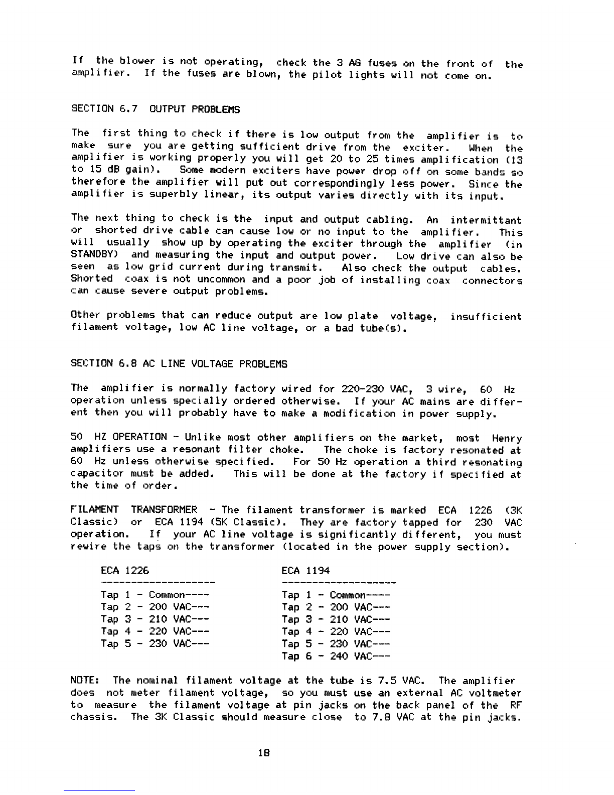
FILAMENT
TRANSFORMER - The filament transformer is marked ECA 1226 (3F`
Classic)
or
ECA 1194 (5K Classic). They are factory tapped for 230 VAC
operation.
If
your AC line voltage is significantly different, you must
rewire the taps on the transformer (located in the power supply section).
ECA 1226
Tap 1 - Common----
Tap 22 - 200 VAC ---
Tap 3 - 210 VAC---
Tap 4 - 220 VAC ---
Tap 5 - 230 VAC----
EEA 1194
Tap 1 -
Common----
Tap 2 - 200 VAC---
Tap 3 - 210 VAC---
Tap 4 - 22r7 VAC---
Tap 5
- 230 VAC---
Tap 6
- 240 VAC---
NOTE:
The nominal filament voltage at the tube is 7.5 VAC. The amplifier
does not meter filament voltage, so you must use an external AC voltmeter
to
measure the filament voltage at pin jacks on the back panel of the RF
chassis.
The 3K Classic should measure close to 7.8 VAC at the pin jacks.
18

The 5F': Classic
filaments
are in series and the voltage should read about
15.6 VAC.
becaf the voltage varies more than 5% from these figures, the
taps on the filament transformer should be changed.
HIGH VOLTAGE
TRANSFORMER
- The 3F,
Classic Mark II domestic amplifier is
supplied with
the ECA 1120A. The
primary
tap connections
are listed below:
ECA 11 2UA
23C+ VAG--------------- T'ap 1
:-----Tap 3
:------Tap 5
213r?
VAC---
-------Tap 7
The 31C
Classic X and 5K Classic are supplied with one of the following high
voltage transformers:
ECA 1171 or ECA 1*214A
i= ^,mm,^n------^-----------Tap 1
'.,Uo-2n1 r) VAiJ---------- Tap i
'210-234 VAL:-..-------.---Tap 3
::30-12"40 VAC-.----------Tap 4
The
high voltage transformers are located on the bottom plate of the power
supply section.
SECTION 6.9 OTHER PROBLEMS
AMPLIFIEF? WILL NOT TURN ON The most likely cause is the circuit breaker.
Check
the continuity of the circuit breaker with an ohmmeter if the unit
will
not turn on or off.
Another possible cause is the improper instal-
lation of the power plug on the power cable. If the high voltage turns on,
but the pilot lights, blower, and relay supply do not come on the 3 AG fuse
has blown.
ALC
CIRCUIT
SHORTED
A defect in the ALE circuit will prevent the tubes
from being driven properly.
FILAMENT
VOLTAGE FAILURE With a ceramic tube it is not easy to make sure
that the filaments are lighting. If the filaments are lighting correctly,
the air flow from the amplifier should feel warm. If the filaments are not
lighting,
the amplifier will not draw any resting plate current when it is
keyed.
The filament voltage passes through a 4 pin Jones plug into the RF
chassis, so you have no filament first check that the plug is properly con-
nected.
After that you would have to check the filament transformer, the
filament
choke on the bottom of the RF chassis, or a problem at the tube
socket.
Check the filament voltage at the pin jacks on the rear panel of
the RF deck. It should be 7.8 VAC for the 3K and 15.6 VAC for the 5K.
19
Other manuals for 3K Classic Mark II
2
This manual suits for next models
2
Table of contents
Other Henry Radio Amplifier manuals

Henry Radio
Henry Radio 3K Classic Mark II User manual

Henry Radio
Henry Radio 2KD-5 Operating instructions

Henry Radio
Henry Radio 3K Classic Mark II Operating instructions

Henry Radio
Henry Radio 2K-Classic Operating instructions

Henry Radio
Henry Radio 3K Ultra Operating instructions

Henry Radio
Henry Radio C100D Series Operating instructions

Henry Radio
Henry Radio Tempo 2000 User manual


