Soulution 710 User manual

Power
Power Power
Power Amplifier
AmplifierAmplifier
Amplifier 710
710 710
710
User manual
User manualUser manual
User manual
soulution
nature of sound


Power
PowerPower
Power
Amplifier
AmplifierAmplifier
Amplifier
710
710710
710
User Manual
Page 1
Dear client
Dear clientDear client
Dear client
We are proud that you decided yourself for a soulution amplifier. You ha e acquired
an amplifier with outstanding sonic performance which you will enjoy for many
years.
We understand your eagerness to get started but e en though please study this
manual step by step before you integrate the power amplifier 710 in your High Fi-
delity system. This manual contains also useful tips for the optimisation of your
o erall HiFi-system.
If there are any questions regarding the start-up or operation of your power amplifier
710 please do not hesitate to contact your dealer.
Ha e
Ha e Ha e
Ha e fun!
fun!fun!
fun!
Your soulution
Your soulution Your soulution
Your soulution -
--
- team
team team
team

soulution
nature of sound
Seite 2
CE
CECE
CE-
--
-Declaration of C
Declaration of CDeclaration of C
Declaration of Conformity
onformityonformity
onformity
Spemot AG declares that this product is in conformance with the following direc-
ti es and standards:
Low Voltage Directi e 2006/95/EG (EN/IEC 60065:2002)
Electromagnetic Compatibility 2004/108/EG (EN 55013:2001, EN 55020:2002,
EN 61000-3-2:2006, EN61000-3-3:1995)
FCC
FCCFCC
FCC-
--
-Notice
NoticeNotice
Notice
Note: This equipment has been tested and found to comply with the limits for a
Class B digital de ice, pursuant to Part 15 of the FCC Rules. These limits are de-
signed to pro ide reasonable protection against harmful interference in a residential
installation. This equipment generates, uses and can radiate radio frequency energy
and, if not installed and used in accordance with the instructions, may cause harm-
ful interference to radio communications. Howe er there is no guarantee that inter-
ference will not occur in a particular installation.
If this equipment does cause harmful interference to radio or tele ision reception,
which can be determined by turning the equipment off and on, the user is encour-
aged to try to correct the interference by one or more of the following measures:
-
adjust or relocate the recei ing antenna
-
increase the separation between the equipment and the recei er
-
connect the equipment into a mains outlet on a circuit different from that to
which the recei er is connected
-
consult the dealer or an experienced radio/TV technician for help
Disposal
DisposalDisposal
Disposal
According to the Directi e 2002/96/EG of the European Parliament used
consumer-electro technical appliances ha e to be disposed separately
and ha e to be indicated with the following symbol.
In the case of disposal of this component please do so in conformity with legal and
en ironmental regulations.

Power
PowerPower
Power
Amplifier
AmplifierAmplifier
Amplifier
710
710710
710
User Manual
Page 3
Table of Content
Table of ContentTable of Content
Table of Content
1
Quick start.......................................................................................... 5
2
Important security ad ices: .................................................................. 6
3
Technical Highlights............................................................................ 8
3.1
Layout ................................................................................................ 8
3.2
Amplification circuit............................................................................ 8
3.3
Power supply ...................................................................................... 8
4
Start of operation and handling of the power amplifier 710 .................... 9
4.1
Scope of deli ery and packing .............................................................. 9
4.2
Optimal positioning of your power amplifier 710.................................... 9
4.3
Rear panel of the power amplifier 710................................................ 11
4.4
Front panel of the power amplifier 710 ............................................... 15
5
Protection functions of the power amplifier 710 .................................. 17
6
Trouble shooting ............................................................................... 18
6.1
Actions after the appearance of an error.............................................. 18
7
Care and maintenance ....................................................................... 19
7.1
Burn-In ............................................................................................ 19
7.2
Longlife-precautions .......................................................................... 19
7.3
Cleaning ........................................................................................... 19
8
Ser ice ............................................................................................. 20
9
Guarantee......................................................................................... 20
10
Technical data .................................................................................. 21
11
Dimensions....................................................................................... 23
12
Definitions........................................................................................ 24


Power
PowerPower
Power
Amplifier
AmplifierAmplifier
Amplifier
710
710710
710
User Manual
Page 5
1
11
1Quick start
Quick startQuick start
Quick start
Unpacking
UnpackingUnpacking
Unpacking
Unpack the power amplifier 710 and store the packing for fu-
ture transportations.
Security ad ice: Ne er lift the power amplifier
710
by yourself. Take the required precautions for the trans
port
of an apparatus of this weight. (ca. 80 kg)
Positioning
PositioningPositioning
Positioning
Position the power amplifier 710 on a stable base
that is able to
support min. 80kg.
Security ad ice: Cooling air must be able to circu-
late and escape unrestricted.
Cab
CabCab
Cabling
lingling
ling
Disconnect all electrical appliances of your HiFi-
system from the
mains supply. Connect your power amplifier 710 with your pre-
amplifier (according to user manual).
Use the respecti e signal
cables and the cable for the LINK-system. Connect the
power
amplifier 710 with your loudspeakers. Reconnect the
power
amplifier 710 and all other components of your HiFi-
system
with mains supply. Please use
the enclosed high class mains
cable.
Security ad ice:
While manipulating with cables the
power amplifier 710
has to remain disconnected from the
mains. Check the cables for tight fit or e entual d
amages of
the cables potentially leading to short circuits.
S
SS
Settings
ettingsettings
ettings
Define the brightness of the display, the start-
input as well as
the start-mode.
Security ad ice: Start-
mode ON should only be used
if the power amplifier 710 cannot be controlled i
a the
front-panel and the LINK-connection is not a ailable.
Switch
SwitchSwitch
Switch on
on on
on
Switch on your source de ices and preamplifier.
Turn down the
olume of the preamplifier to a minimal le el.
Switch on your
power amplifier 710.
Security ad ice: Before you switch on your
power
amplifier 710 for the first time the Start-
Mode must be
OFF.

soulution
nature of sound
Seite 6
2
22
2Important
ImportantImportant
Important
s
ss
security ad ice
ecurity ad iceecurity ad ice
ecurity ad ices
ss
s:
::
:
User Manual
User ManualUser Manual
User Manual:
::
:
Read this user manual carefully before you start-up your power amplifier 710 and
follow all installation and security ad ices.
Please keep this user manual. In the case this manual gets lost you ha e the possi-
bility to download it from the soulution-webpage.
(http://www.soulution-audio.com/downloads)
Mains:
Mains:Mains:
Mains:
Exclusi ely use 3 phase power cords with ground conductor. The may not be
crushed by objects.
Unplug your power amplifier 710 from the mains connection in the following cases:
-
before you manipulate with cables
-
before you clean your amplifier
-
during thunder storms or
-
before you lea e for longer periods
Operation
OperationOperation
Operation:
::
:
Ne er run your power amplifier 710
-
with opened housing
-
with closed cooling-slots
-
with high ambient temperatures (>40°C)
-
close to heat sources like radiators, heatings, o ens or similar appliances dis-
sipating heat
-
with extremely high humidity for example in humid cellars or rooms similar
humidity
-
close to water (Sink, bathtub, or similar equipment)

Power
PowerPower
Power
Amplifier
AmplifierAmplifier
Amplifier
710
710710
710
User Manual
Page 7
Cleaning
CleaningCleaning
Cleaning:
::
:
Use a soft and dry towel. We suggest using a non abrasi e micro fibre towel. Please
do not use any sol ents or liquidities.
Transport:
Transport:Transport:
Transport:
Use only with the cart, stand, tripod, bracket or table specified by the manufacturer
or sold with the apparatus. When a cart is used, use caution when mo ing
cart/apparatus combination to a oid injury or tip o er.
Packing
PackingPacking
Packing:
::
:
Please keep the original packing for future transports. The original packing is opti-
mal protection against potential damages.
Ser ice:
Ser ice:Ser ice:
Ser ice:
Do not try to repair your power amplifier 710 by yourself. It needs a ser ice check
by a qualified person in the following cases:
-
the mains-cable or the mains connectors are damaged
-
foreign substances or liquidity has entered the power amplifier 710
-
the power amplifier 710 has seen rain
-
the power amplifier 710 seems to malfunction
-
the power amplifier 710 has fallen to the floor or the housing is damaged
Seri
SeriSeri
Serial
alal
al-
--
-Nr.:
Nr.:Nr.:
Nr.:
710
710 710
710 -
--
-
Please note the serial-number of your power amplifier 710 abo e.

soulution
nature of sound
Seite 8
3
33
3Technical
TechnicalTechnical
Technical Highlights
Highlights Highlights
Highlights
3.1
3.13.1
3.1 Layout
LayoutLayout
Layout
The power amplifier 710 is realised as symmetrical dual mono circuit. Left and
right audio channel each has identical circuit boards. The o erall layout has been
optimised for shortest signal paths. All high current signal paths ha e solid copper
bars for minimal losses. Critical components ha e been stabilised with massi e
aluminium plates.
3.2
3.23.2
3.2 Amplification circuit
Amplification circuitAmplification circuit
Amplification circuit
Immediately following the input connector the music signal is buffered in the power
amplifier 710 and is therefore transmitted with low impedance to the entrance of
the following error amp, an extremely fast operation amplifier whose negati e feed-
back seizes de iations fast and precise thanks to the high process-speed, pro iding
for a corrected howe er still non-amplified incoming signal. Next follows the true
core element of the power amplifier 710: the “fixed gain”- oltage amp. This highly
linear (0.1 dB le el de iation, 0.005% THD+N) amplifier stage can perform its full
precision only under constant thermal conditions; therefore it is combined jointly
with the error amp in a module casted with synthetic resin.
Per channel fourteen bipolar power transistors fixed on a massi e copper rail and
permanently temperature controlled for a constant idle current, pro ide finally for
the gigantic current rating of the power amplifier 710 of more than 60 ampere.
3.3
3.33.3
3.3 Power supply
Power supplyPower supply
Power supply
With the gi en linearity of the amplifier-stages it is in our iew finally the stability of
the supply oltages, being the power supply unit, deciding if a properly working am-
plifier is truly well sounding. The power supply unit of the power amplifier 710 is
equipped with two 1’000VA- toroidal transformers, capacitors with a total capacity
of nearly 250’000 microfarad and discrete rectifiers. All in all we use 10 separated
power supply units. The power supply for both the error- amp and the “fixed-gain”-
amp is stabilized in arious stages.

Power
PowerPower
Power
Amplifier
AmplifierAmplifier
Amplifier
710
710710
710
User Manual
Page 9
4
44
4Start of operation a
Start of operation aStart of operation a
Start of operation and
nd nd
nd handling
handlinghandling
handling
of the
of the of the
of the power
power power
power amplifier
amplifier amplifier
amplifier 710
710710
710
Please take care while installing the power amplifier 710. Follow all security ad-
ices!
4.1
4.14.1
4.1 Scope of deli ery and packing
Scope of deli ery and packingScope of deli ery and packing
Scope of deli ery and packing
Please check the scope of deli ery:
-
power amplifier 710
-
mains cable
-
user manual
-
2 pair cotton-glo es
Please store the packing of the power amplifier 710 for future transports. Check
your power amplifier 710 for transport damages. In the case your power amplifier
710 is damaged please contact your soulution dealer.
Security ad ice: If your power amplifier 710 is still ery cold from the
transport, please let it warm within the packing, in order to omit condensation of
water inside your power amplifier 710.
The power amplifier 710 has a high quality surface. Please be careful while trans-
porting your power amplifier 710 so that the surface does not get scratched. Please
use the enclosed cotton glo es.
Ne er position your power amplifier 710 on the front panel. The display glass could
get scratched or e en burst.
4.2
4.24.2
4.2 Optimal
OptimalOptimal
Optimal
positioning of your
positioning of your positioning of your
positioning of your power
power power
power amplifier
amplifieramplifier
amplifier 710
710 710
710
There are no limitations on where to position your power amplifier 710. We suggest
positioning it so that the connecting cables to the loudspeakers and the preamplifier
remain short.
Please ensure ample distance to other components for unhindered circulation and
dissipation of cooling air.

soulution
nature of sound
Seite 10
The power amplifier 710 reaches an operating temperature of ca. 45°C. The speed
controlled fan will only be used if the ambient temperature is significantly abo e
25°C or if listen at high olumes for longer periods.
Security ad ice: Ne er lift the
Ne er lift the Ne er lift the
Ne er lift the power
power power
power amplifier
amplifier amplifier
amplifier 710
710 710
710 alon
alonalon
alone
ee
e!
!!
!
The power amplifier 710 has a weight of. 80 kg. Ensure that nobody gets insured
while transporting your power amplifier 710. Please ensure that you do not squeeze
your fingers or feet. (do not tip o er laterally!)
Check whether the base is able to hold at least 80 kg. In case of doubt position your
power amplifier 710 on the floor.

Power
PowerPower
Power
Amplifier
AmplifierAmplifier
Amplifier
710
710710
710
User Manual
Page 11
4.3
4.34.3
4.3 Rear
RearRear
Rear panel
panel panel
panel of the
of the of the
of the power
power power
power amplifier 710
amplifier 710amplifier 710
amplifier 710
Rear panel of the power amplifier 710
4.3.1
4.3.14.3.1
4.3.1 Mains
MainsMains
Mains (A)
(A) (A)
(A)
Connect the power amplifier 710 with the mains supply. The enclosed power cord is
optimised for this application.
After switch-on of the mains switch the standby power supply of the power amplifier
710 gets started. The display shows "WAIT". As soon as constant conditions are
reached the power amplifier 710 changes to operating condition OFF (red LEDs in
display).
Security ad ice: Only switch-off the mains connection if your power
amplifier 710 is in operating condition OFF.
4.3.2
4.3.24.3.2
4.3.2 Input (B)
Input (B)Input (B)
Input (B)
Your power amplifier 710 has a symmetrical and an asymmetrical signal input. For
longer connecting cables we suggest to use the symmetrical inputs. For shorter sig-

soulution
nature of sound
Seite 12
nal paths also asymmetrical cables warrant a high class connection. Top quality
connecting cable and optimal layout prerequisite.
Security ad ice: Please follow the security ad ices on page 6!
While manipulating with cables the power amplifier 710 has to remain discon-
nected from the mains. Before you disconnect the mains the power amplifier 710
has to be in operating condition OFF.
Due to the ery high current impulse rating of your power amplifier 710 a wrong ca-
bling or defecti e cables may destroy your loudspeakers.
Excessi e olumes due to in appropriate handling may cause hearing damages.
4.3.3
4.3.34.3.3
4.3.3 Speaker (C)
Speaker (C)Speaker (C)
Speaker (C)
Connect your loudspeakers to the power amplifier 710. The tremendous stability of
the power amplifier 710 ensures optimal operation for all types of speaker cables.
We recommend using top quality speaker cables with spade lugs.
Security ad ice: Please follow the security ad ices on page 6!
While manipulating with cables the power amplifier 710 has to remain discon-
nected from the mains. Before you disconnect the mains the power amplifier 710
has to be in operating condition OFF.
Check the connectors for tight fit. Check the cables for e entual damages. Short cir-
cuits pro oked by thin threads form loudspeaker cables may end in a fire.
The power amplifier 710 comes with CE-darners which only can be remo ed with
tools.
4.3.4
4.3.44.3.4
4.3.4 LINK
LINKLINK
LINK (D)
(D) (D)
(D)
With the LINK-system the power amplifier 710 can be remote controlled by the pre-
amplifier 720/721. Connect the Sla e-In of your power amplifier 710 with the Mas-
ter-out of the preamplifier 720/721. With Next-Sla e you may connect further com-
ponents to the LINK-network.

Power
PowerPower
Power
Amplifier
AmplifierAmplifier
Amplifier
710
710710
710
User Manual
Page 13
4.3.5
4.3.54.3.5
4.3.5 Settings (E)
Settings (E)Settings (E)
Settings (E)
The settings define the condition of your power amplifier 710 after switch on of the
mains.
Important: New settings for Start-Mode, Start-Input and Bright-
ness are acti ated only after switch on of the mains.
4.3.5.1
4.3.5.14.3.5.1
4.3.5.1 Start
StartStart
Start-
--
-Mode
ModeMode
Mode
Start-Mode defines the operating condition after switch-on of the mains
(ON/OFF/LINK).
Start
StartStart
Start-
--
-Mode
ModeMode
Mode ON:
ON: ON:
ON:
After switch on of the mains the power amplifier 710 is started automatically. It can
only be switch-of after it has reached the operating condition ON.
Start
StartStart
Start-
--
-Mode OFF:
Mode OFF:Mode OFF:
Mode OFF:
After switch on of the mains the power amplifier 710 changes to the operating con-
dition OFF.
Start
StartStart
Start-
--
-Mode
Mode Mode
Mode LINK
LINKLINK
LINK:
::
:
After switch on of the mains the operating condition of the power amplifier 710 gets
controlled by the preamplifier. If the LINK–connection is missing the amplifier
changes to operating condition OFF.
Security ad ice: We suggest the use of Start-Mode ON only if the front
panel of the power amplifier 710 is not access able and the LINK – system is not
installed.
Please be aware that the amplifier will start-up automatically and unattended after
power blackout.
4.3.5.2
4.3.5.24.3.5.2
4.3.5.2 St
StSt
Start
artart
art-
--
-Input
InputInput
Input
With Start-Input the acti e input after switch-on is defined (1. SYM / 2. ASYM).

soulution
nature of sound
Seite 14
4.3.5.3
4.3.5.34.3.5.3
4.3.5.3 Brightne
BrightneBrightne
Brightness
ssss
ss
The brightness of the display can be changed in three le els (1=low / 2=medium /
3=high).
4.3.6
4.3.64.3.6
4.3.6 RS232
RS232 RS232
RS232 –
––
– Interface (F)
Interface (F) Interface (F)
Interface (F)
The power amplifier 710 can be remote controlled through the RS232 interface. All
functions can be controlled and rele ant information is pro ided to the control unit.
4.3.7
4.3.74.3.7
4.3.7 Type label
Type labelType label
Type label (
( (
(G
GG
G)
))
)
Please note the serial number of your power amplifier 710 on page 7 of this user
manual. This allows you to ha e the product specific data at hand without remo ing
your power amplifier 710 from the HiFi rack.
Power
PowerPower
Power
Amplifier
AmplifierAmplifier
Amplifier
710
710710
710
User Manual
Page 15
4.4
4.44.4
4.4 Front panel of the
Front panel of the Front panel of the
Front panel of the power
power power
power amplifier
amplifier amplifier
amplifier 710
710710
710
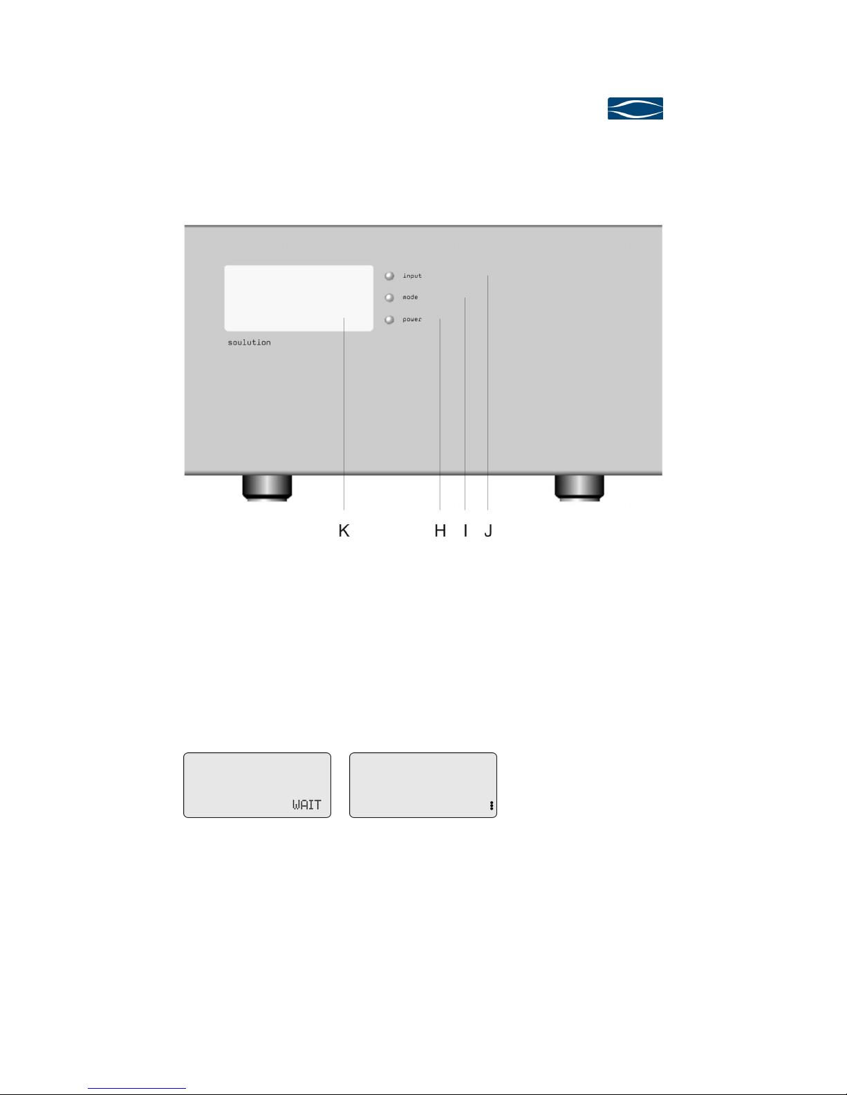
Front panel of the power amplifier 710’
4.4.1
4.4.14.4.1
4.4.1 Power (
Power (Power (
Power (H
HH
H)
))
)
With the Power-button you define the operating condition ON or OFF (red LEDs). In
operating condition OFF the loudspeaker terminals are muted. The loudspeaker
terminals are only acti ated if the amplifier is ready for operation and if no errors
are present.
Display after switch on of the
mains switch
Display in operating condition
OFF
soulution
nature of sound
Seite 16
4.4.2
4.4.24.4.2
4.4.2 Mode
ModeMode
Mode (I
(I (I
(I)
))
)
LINK function delegates the control of the start-up sequence to the preamplifier
720/721. The preamplifier 720/721 is the master of this master-sla e control. In
operating condition NORM the control o er the start-up sequence remains with the
power amplifier 710 independently of a connected LINK-cable.
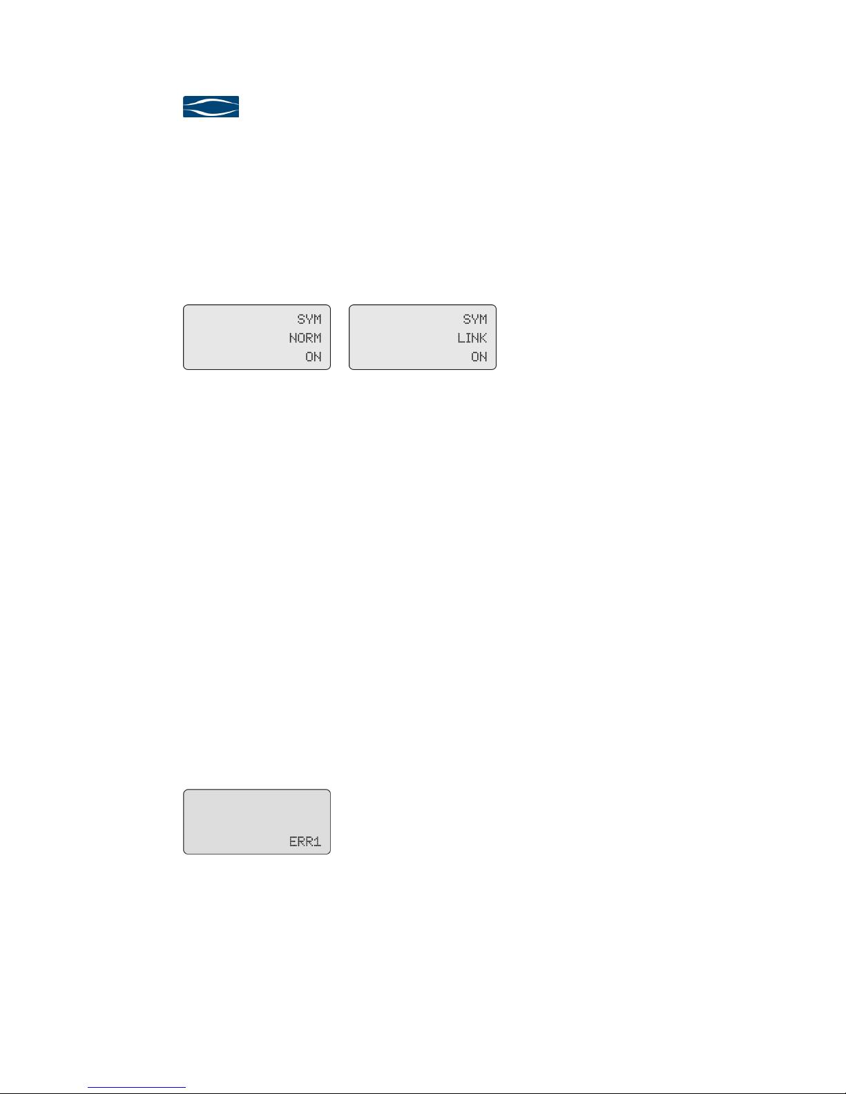
Display in operating condition ON,
Mode NORM
Display in operating condition ON,
Mode LINK
The Power-button remains acti e. The amplifier soulution 710 can always be
switched off ia the front panel.
4.4.3
4.4.34.4.3
4.4.3 Input (
Input (Input (
Input (J
JJ
J)
))
)
Your power amplifier 710 has symmetrical (SYM) and asymmetrical (ASYM) input
connectors. The selection is made comfortably at the press of a button on the front
panel. The non acti e input is terminated. We suggest the use of the symmetrical
connectors if possible.
4.4.4
4.4.44.4.4
4.4.4 Display (K)
Display (K)Display (K)
Display (K)
The display shows all operating conditions of the functions Power, Mode and Input.
If an error occurs during the start-up sequence or during operation the power ampli-
fier 710 is switched off and lowest column shows ERR1..ERR3.
Display in operating condition
ERR1

Power
PowerPower
Power
Amplifier
AmplifierAmplifier
Amplifier
710
710710
710
User Manual
Page 17
5
55
5Protection functions of the
Protection functions of the Protection functions of the
Protection functions of the power
power power
power amplifier
amplifieramplifier
amplifier 710
710 710
710
Comprehensi e protection functions ensure safe operation and a long lifetime. The
power amplifier 710 has the following protection functions:
Le el limitation
Le el limitationLe el limitation
Le el limitation:
::
:
For to high le els at the input of the power amplifier 710 the soft clip circuit is ac-
ti ated. The acti ated soft clip circuit will distort the output signal significantly, the
sonic performance is reduced. Please ensure that the input le els are within the
limit of 1.8 Vrms.
O ercurrent
O ercurrentO ercurrent
O ercurrent:
::
:
For an output current of > 60 A to the loudspeakers the power amplifier 710 is
switched off automatically. This represents a maximal impulse power rating of ca.
3’000 W (48 V @ 0.8Ω)
O ertem
O ertemO ertem
O ertemperature
peratureperature
perature:
::
:
The temperature of the power transistors is permanently monitored. If the maximal
operating temperature is exceeded despite of acti e cooling system the power am-
plifier 710 is switched off automatically.
Fuse
FuseFuse
Fuse
The mains connection has a fuse which protects your amplifier against too high
power consumption. Please replace with the same fuse type. The fuse is located
within the mains switch on the rear side of the power amplifier 710.
Model 230 V, 50-60Hz 10A/T 250V micro fuse 5x20mm
Model 220 V, 60Hz 10A/T 250V micro fuse 5x20mm
Model 120 V, 50-60Hz 16A/T 250V micro fuse 5x20mm
Model 100 V, 50-60Hz 16A/T 250V micro fuse 5x20mm

soulution
nature of sound
Seite 18
6
66
6Trouble shooting
Trouble shootingTrouble shooting
Trouble shooting
Error
ErrorError
Error
Action
ActionAction
Action
No display
No displayNo display
No display
Check the cabling to the mains supply. E entually replace the
fuse of your power amplifier 710.
No music
No musicNo music
No music
Check the cabling to your preamplifier and the loudspeakers
,
whether the correct input (SYM/ASYM) is acti ated, whether
the
preamplifier is switched on and if the right source has been se-
lected. Check whether output signal at your source and pream-
plifier is a ailable. (Mute, Pause, etc.).
ERR
ERRERR
ERR1..3
1..31..3
1..3
after
after after
after
switch on
switch onswitch on
switch on
Switch off the mains of your power amplifier 710 for 15 sec-
onds and switch on again. If the error has not disappeared
please contact your soulution dealer.
ERR
ERRERR
ERR1
11
1..3
..3..3
..3
for
forfor
for
OFF
OFF OFF
OFF -
--
->
> >
> ON
ONON
ON
Check the cabling, the mains oltage (O er-/Under oltage
) and
the le el of the input signal.
If the error has not disappeared please contact your soulution
dealer.
ERR
ERRERR
ERR1..3
1..31..3
1..3
in o
in oin o
in op-
p-p-
p-
eration
erationeration
eration
Switch off the mains of your power amplifier 710 for 15 sec-
onds and switch on again. If the error has not disappeared
please contact your soulution dealer.
6.1
6.16.1
6.1 Actions after the appearance of an error
Actions after the appearance of an errorActions after the appearance of an error
Actions after the appearance of an error
If you con not identify the error please disconnect the mains supply (before you dis-
connect the power amplifier 710 has to be in operating condition OFF) and contact
your soulution dealer.
Other manuals for 710
1
This manual suits for next models
2
Other Soulution Amplifier manuals


