Henseleit Three-Dee RIGID User manual

Three-Dee
RIGID
Version 2010-2011
M a n u a l
March 2011
Jan Henseleit
A T T E N T I O N! I M P O R T A N T!

Please read the manual before opening the bags
Table of ontents
Safety instructions: p. 3
TD- Rigid: Description and technical data p. 4
Parts list: List of all parts of the single assembly groups p. 7
Technical data / Accessories p. 8
Introduction: Important! General information for the assembly p. 9
hapter I Main rotor ( Assembly group 1 ) p. 10
hapter II Rotor shaft unit ( Assembly group 4 ) p. 12
hapter III Intermediate shaft unit ( Assembly group 5 ) p. 13
hapter IV Tail boom ( Assembly group 8 ) p. 14
hapter V hassis ( Assembly group 2 ) p. 15
Pre-assembly of the upper part of the chassis p. 15
Ad ustment of the gear play p. 16
Pre-assembly of the lower part of the chassis p. 17
Assembly of the upper part to the lower part of the chassis p. 18
hapter VI R preparation ( Servos ) p. 19
hapter VII ontrol and servo assembly ( Assembly group 6 ) p. 20
hapter VIII Assembly of the electric motor ( Assembly group 7 ) p. 23
hapter IX Tail gear ( Assembly group 9 ) p. 25
hapter X Assembly and struts of the tail boom ( Assembly group 8 ) p. 30
hapter XI Assembly of the electronic parts ( V- Stabi / receiver / controller / batteries ) p. 32
hapter XII V-Stabi onnection and programmation p. 36
hapter XIII Final tasks ( anopy etc. ) p. 38
hapter XIV Adjustments ( V-Stabi, rotor blades, throttle curves etc. ) p. 39
hapter XV Directions for initial flight ( RPM, operating limits, hints etc. ) p. 42
hapter XVI Maintenance / spare parts p. 45
2

Safety Advice
A remote controlled helicopter is not a toy and must be kept out of the hands of children.
Only correctly assembled helicopters, that are maintained regularly, after each flight, can function properly.
Keep a safe distance from the helicopter and always assume that something may go wrong at any time causing it to become
uncontrollable.
If repairs have to be carried out only use original parts that you can order directly in my web-shop.
Lack of attention to detail, or mistakes in the helicopter assembly, or assembly of components and a lack of experience in
using the radio control can result in the helicopter becoming uncontrolled and dangerous. Due to the enormous kinetic energy
in the rotors, there is a risk of fatal in uries or death and damage of any type can occur due to lack of attention.
Therefore do not fly over people, cars or anything else that might be in danger. Safety is very important and is your
responsibility, as the manufacturer and the sales agents have no control over the use or maintenance of the Three-Dee
RIGID.
The company Henseleit Metallverarbeitung and it sales representatives are not liable or responsible for any damage or
in uries arising from products out of their supply programme and therefore are not responsible in any way, as proper use or
assembly can not be supervised by us.
I strongly recommend that you do not use products that are not documented and specified in my handbook. An up to date
spare part price list can be obtained from me or my sales agents. You also will find current information on my website.
The copying of text or text extracts, drawings and pictures is only allowed with my prior agreement in writing.
Jan Henseleit
3
T h r e e - D e e R I G I D
The TDR was the first 1.6 meter class production helicopter worldwide which was only delivered with a Rigid main rotor for
flybarless flying.
In my opinion the flybar will not be used any more in future. Due to the technological progress the rise of the electric
helicopter in all sizes cannot be prevented any more either. The advantages prevail concerning nearly all points, so that the
further development is more or less predictable.
Because of the apparent demand for flybarless electric helicopters the development of a light system without any
compromises was the consequent step to apply new standards and to get a compact model especially being ad usted to the
3 axis stabilisation, which perfectly supports the completely new possibilities.
Concept:
In general it is not possible to re-invent the wheel. Over the years I have presented innovations and tried various possibilities
that have also been adapted in other areas. Some day you approach a constructive solution offering all possible physical
features.
There are always different possibilities to achieve the aim. However, after some time there is also the danger that only the
design is modified not resulting in flight-technical advantages. I am interested in building a system that is determined by a
clever assembly of the absolutely necessary components and a minimum number of parts.
In my opinion a straight and clear design is the advantage of this helicopter. For the first time I decided to use a two-stage
drive in my helicopters.
Due to the positive experiences using the MP series with the spiral cut gear wheels module 1 concerning the efficiency,
robustness and operating noise the different constructive advantages prevail in spite of the small loss caused by the second
stage.
In contrast to the predecessor possible savings could be achieved because the production of the smaller gear wheels is less
complex and problematic and the one-way drive shaft can be smaller because it is mounted on the intermediate shaft.
In opposite to belt driven systems the efficiency is much higher which save a lot of battery power.
The rigidity of the entire mechanics is increased without using additional stiffening elements. The extremely compact
assembly of the transmission unit which is the core of the mechanics results in an optimal assembly of the two tail boom
mountings that are located far from each other as well as an optimal support of the main rotor shaft.
The distance between the upper mount plate and the compact main rotor centre hub is smaller than in any other helicopter of
this size, so that the bending stress on the hollow 10mm main rotor shaft does not cause any problems.
The complete tail gear drive has got an improvement and in opposite to the TDR-2009 all gears are manufactured with milling
machines so that the tolerance is much better than of the in ection plastic gears before.
A horizontal stabiliser was not used any more. This part is not really necessary and it interferes with the flight. Besides it
increases the weight as well the vibrations and is difficult to transport (it is amazing how much easier it is to place the
helicopters without horizontal stabiliser next to each other and turned by 180° in the car).
Thanks to the remarkably slender and futuristic design of the helicopter you do not miss the horizontal stabiliser.
4

For people who have not much space in their cars it is especially advantageous that the tail boom including the front pinion,
the struts and the push rod can be removed from the helicopter within less than a minute.
In order to do so, you only have to detach both struts as well as the push rod in the front area of the mechanics, loosen the
two lower attachment screws of the tail boom holder and pull out the tail boom to the back.
The tail boom is automatically fixed at the correct position in the front holder, so that it is always exactly aligned after having
been pushed in.
The carbon chassis structure can be divided into the upper and the lower part, whereas the robust upper part includes all
components necessary for the flight and the lower part only contains the battery and my obligatory skid plates.
Thus the light mechanics can perfectly be integrated into the fuselages because for this purpose the lower part can be
removed completely in order to mount corresponding fastening angles. The advantage of a mechanics consisting of a flyable
upper part where only a stable battery support and the skid plates are attached at the lower area is its great flexibility for
different individual uses that can be realised later.
All batteries up to dimensions of 60x60x360mm can easily be inserted into the protecting slot of the „Rigid“ from the front as
well as from the back.
The spacers are covered with a silicon tube such that the battery is held in a non-slip and safe position by only two Velcro
strips.
The entire mechanics is extremely easy to maintain and can be mounted and dismounted quickly.
The gear stages can be assembled and disassembled individually without having to dismount the entire mechanics. It is also
possible to assemble and disassemble all servos without dismounting the mechanics.
After adding the recommended equipment inclusive blades the helicopter ready to fly has a weight of about 3,1kg without the
drive battery.
Using a 12s accumulator of 3700mAh and 1200g a take-off weight of nearly 4.3kg can be reached, which is an amazing
value for an all-metal carbon helicopter with this rigidity, stability and life time.
The futuristic canopy with its distinctively surrounding line as well as its concave recesses guarantees a considerably better
visibility due to the increased height. It also underlines the very compact appearance.
The low distance between the upper side of the mechanics and the main rotor results in completely new proportions. Thus
the actual rotor is located directly above the canopy, which gives the helicopter a very racy design.
People who know me have experienced that I set a high value on 3D performance as well as on fast speeds since I have built
my first helicopter, the old, blue Three Dee. In my opinion there is nothing more elegant and fascinating than a helicopter
dashing through the air with high speed and blade noises like a pod racer.
That is the reason why the Rigid canopy was designed a bit more aerodynamically which is shown by the extreme high speed
flight qualities, forwards as well as backwards.
The V-Stabi electronic system offers completely new perspectives regarding the high speed flight, which were not possible
when using a flybar. So the advantage of an aerodynamic casing is even more considerable.
Try speeding. It is fun, looks elegant and helps to relieve stress and to relax.
During the flight events it is a popular alternative to flying within a small area of 10x10 m which is nowadays quite common.
For the „aged ones“ among us who are older than 25 years old it is still good to cope with because it does not require such
quick reactions but more sensitiveness and an eye for spacing.
You will also en oy loopings with a diameter of 150 m or nice slow rolls like being drawn over the entire field on a string.
But be careful, slowly approach spacious flying over longer distances, it has to be learnt!
For many years I have known of the problems that layman have during the quite complicated lacquering process. That is why
I developed a high-quality, UV resistant decal set with a window and a comet tail to give the helicopter a typical, distinctive
design. It can be attached by every reasonably skilful user.
The result looks like a high-gloss clean lacquering without frayed edges and is much cheaper and quicker to apply than every
kind of lacquering.
In general, it was my aim to keep the costs of replacement parts as low as possible, so that the nice helicopter will not only be
used on Sundays. That is why I decided to use again my well-proven blackly anodised 25mm aluminium tail boom. In my
opinion the still increasing costs for carbon tail booms because their more precious look are not ustified and after a crash
they can be a considerable cost factor.
When using a flybarless helicopter the flight properties mostly depend on the used stabilisation electronics to emphasise the
quality and performance of the mechanics. So I recommend the flybarless V-Stabi system developed by Uli Röhr and
distributed by Mikado.
The recommended engine using a Pyro 700–52 (with standard shaft) in connection with the successfully operating Jive
controller not requiring any receiver power supply is the optimal configuration for this helicopter at present.
Test flights have shown that this setup in 12s operation allows a speed of approx. 1900 rpm at a pitch of up to 14 degrees, if
necessary.
I think that the standard Pyro 700-52 or something similar like the Scorpion 4035-560KV with about 3 to 4kw is strong enough
for 98% of the pilots.
There are motors with more power but the difference in maximum speed is so little that it makes no sense in my eyes. I think
that stronger motors can be an option for people who only wants to fly fast on a long straight distance. (for records and so on)
If you dive down from a higher altitude you will have no difference in speed.
The disadvantages of big motors is a higher weight and a much higher temperature which will stress the plastic gear of the
first gear step. So have to be very carefully not to break many gears during flight because of to high temperature.
5

Also bigger batteries will be necessary which also add up weight and the complete helicopter gets very hot under the canopy
which may ends in electronic failure.
A easy way to otimize the TDR with the recommended motor for speeding is to set the ESC to 100% and use 15 teeth pinion
with a 12s setup than you will have plenty of power and speed
In this configuration there are some details which you have to observe. You will find some informations about that in chapter
XV “Directions for initial flight”
In general, this light helicopter also allows an 10s operation with brilliant performance values. Because of the low difference in
price between the 10s and 12s batteries the decision which battery to use is problably not too difficult.
Flight attempts have shown that a slightly higher capacity is needed for the same flight time when using 10s batteries. The
reason for this is the higher power consumption at a lower voltage. Thus the balance of weight between the 10s and the 12s
is compensated.
The advantage of the 12s is that it offers more power during extreme manoeuvres.
Apart from that the use of 10s provides more power than every optimally ad usted glow version.
In connection with the development of the Rigid numerous test flights with a logger data capture were carried through, which
persuaded me to refrain from the exaggerated present max rotor speed hype.
Thanks to light models with flybarless main rotors it is not necessary any more to race with a rotor head speed exceeding the
limit of 2000. The properties when flying straight on are even fantastic at 1300 rpm at the main rotor. Every flybar head
helicopter would pitch up hopelessly at these manoeuvres.
Most of the 3D figures can be flown because of a lower rotor disc load also using a more moderate head speed. So more
than 1800 rpm at the main rotor are unnecessary when flying this helicopter.
The logger data show that the efficiency of the blades decreases rapidly with increasing head speed, so that most of the
energy is wasted.
For the same flight condition „Hovering at one position“ 570W is required at 1300 rpm at the rotor and at 1850 rpm you
already need 1000W. At more than 2100 rpm 1500W are required, i. e. nearly the triple amount, although you do nothing
more than hovering.
This result shows clearly that the flight time can be increased considerably, if the rotor does not constantly rotate at full
speed. All these results have contributed to and influenced the choice of the speed reduction and the recommended drive of
the Rigid.
Only exception to fly with higher rotor rpm is for speed competitions were the flight time is not important (please also look into
chapter XV)
6

Bag Part-No. Term pcs. Bag Part-No. Term Stk. Bag Part-No. Term pcs.
(-1-) M A I N R O T O R (-4-) M A I N S H A F T U N I T (-8-) T A I L B O O M
RI - 0100 FLYBAR LINK GUIDE 2RI - 0400 SWASH PLATE 1RI - 0800 BOOM 25x920mm 1
RI - 0100a STUD 2x 20 2aTHREADED LINK BALL M3x3 / 9 long 3RI - 0801-2010 SQUARE HEADED COUPLING 2
RI - 0102s O - RING 16x2.5 hard 4bTHREADED LINK BALL M3x4 / 9 long 2RI - 0801a GRUB SCREW M4x4 2
RI - 0103 ROTOR BRAKE CAP 1cDOME HEAD SCREW M3x 6 3RI - 0802 CARBON BOOM SUPPORT 580mm 2
RI - 0105b HEXAGON SOCKET SCREW M3x 8 2dWASHER M3 small 3RI - 0804 ATTACHING BALLS for 0807 2
RI - 0105c HEXAGON SOCKET SCREW M3x 12 2RI - 0410 ROTOR SHAFT (hollow) 1RI - 0804a LENS HEAD SCREW M3x 8 2
RI - 0107 SPACER WASHER 8x 14x 0,2 2RI - 0412 SPACER BUSH 40mm 1RI - 0805 BOOM SUPPORT END 2
RI - 0109-2010 O - RING INNER BUSHER 2RI - 0413 SPACER BUSH 11,5mm 1RI - 0805a HEXAGON SOCKET SCREW M3x 25 1
RI - 0110-2010 FEATHERING SPINDLE tempered 1RI - 0414 MAIN SHAFT GEAR FLANGE 1RI - 0805b NYLOC NUT M3 1
RI - 0111-2010 SPACER WASHER 8x 14x 0,2 2RI - 0414a HEXAGON SOCKET SCREW M4x 18 1RI - 0807 BALL LINK 8mm 2
RI - 0113 RADIAL BEARING 8x 16x 5 4RI - 0414b NYLOC NUT M4 1RI - 0807a THREADED ROD M3,5x 30 2
RI - 0114 BLADEHOLDER 2RI - 0414c WASHER M4 1RI - 0808 TAIL PUSH ROD SUPPORT front 1
RI - 0115 AXIAL BEARING 8x 16x 5 2RI - 0415 SPACER WASHER 10x 16 x 0,5 1RI - 0809 CARBON BOOM SUPPORT CLAMP 1
RI - 0116 PITCHARM 2RI - 0416-2010 MAIN SHAFT GEAR 1RI - 0810-2010 TAIL DRIVE SHAFT 852mm 1
RI - 0116a THREADED LINK BALL M3x4 / 4 long 2RI - 0416a HEXAGON SOCKET SCREW M3x 12 6RI - 0813-2010 DRIVE SHAFT BEARING assembly a-f
RI - 0117 SPACER WASHER 5x 10 x 1 2RI - 0417 SPACER WASHER set (10x16x0,2 / 0,3) PE aBEARING SUPPORT 2
RI - 0119 HEXAGON SOCKET SCREW M5x10 -12.9 2bRADIAL BEARING 10x 15x 4 lose 2
RI - 0120 CENTRE HUB 1cBEARING BUSH 2
RI - 0121a BRASS BUSHING 2(-5-) I N T E R M E D I A T E S H A F T U N I T dCOLLET 2
RI - 0121b BALL LINK 15mm long 4eFINE PITCH THREADED NUT M8x1 2
RI - 0121c STUD BOLT M2,5x 25 2RI - 0506 GEAR WHEEL intermediate shaft 1fLOCKING WASHER 2
RI - 0136 CENTRE HUB BOLT M4x18 1RI - 0510 INTERMEDIATE SHAFT 1gO - RING 16x2.5 hard 2
RI - 0136a NUT - M4 flat 1RI - 0515 SPACER WASHER 10x 16x 0,5 4RI - 0824-2010 PINION for taildrive 1
RI - 0138 SHANKED BLADE BOLT 2RI - 0516 INTERMEDIATE SHAFT PINION 1RI - 0824a GRUB SCREW M4x 4 1
RI - 0138a NYLOC NUT - M4 2RI - 0517 SPACER WASHER set (10x16x0,2 / 0,3) PE RI - 0828 BEARING FLANGE assembly a-d
RI - 0138b SPACER FOR ROTORBLADES 4RI - 0518 ONE WAY DRIVE FLANGE assembly a-c aBEARING FLANGE 1
RI - 0140a FEATHERING SPINDLE SEESAW 1RI - 0518a ONE WAY DRIVE FLANGE 1bRADIAL BEARING 8x 16x 5 2
RI - 0140b FLANGED BEARING 8x 16x 5 2RI - 0518b ONE WAY DRIVE 10x 14x 12 1dHEXAGON SOCKET SCREW M3x 6 2
RI - 0140c COUNTER SUNK SCREW M5x 8 2RI - 0518c RADIAL BEARING 10x 19x 5 2RI - 0830-2010 PINION SHAFT 1
RI - 0140d GRUB SCREW M4x 4 1RI - 0524-2010 CROWN GEAR 1RI - 0831-2010 CLUTCH 1
RI - 0525 HEXAGON SOCKET SCREW M3x 8 12 RI - 0831a CLUTCH INSERT 1
(-2-) H A S S I S RI - 0526 CROWN GEAR FLANGE 1RI - 0831b GRUB SCREW M4x 6 1
RI - 0527 GRUB SCREW M5x 5 2RI - 0833 TAIL BOOM DECAL 2
RI - 0201 UPPER CARBON SIDE FRAME 2
RI - 0202 BOTTOM CARBON SIDE FRAME 2
IRI - 0221 BEARING SUPPORT 1
IRI - 0222 BEARING SUPPORT 3(-6-) L I N K A G E & S E R V O M O U N T
IRI - 0223 RADIAL BEARING 10x 22x 6 4(-9-) T A I L G E A R B O X
II RI - 0232 TAIL BOOM HOLDER FRONT 1III RI - 0616 SWASH PLATE ANTI ROTATION GUIDE 1
II RI - 0233 TAIL BOOM HOLDER BACK 1III RI - 0616a HEXAGON SOCKET SCREW M3x12 2RI - 0900 TAIL GEAR HOUSING assembly a-b
II RI - 0236 CANOPY MOUNT 2III RI - 0616b WASHER M3 small 2IaTAIL GEAR HOUSING 1
II RI - 0237a STUD BOLT M3x 72 4IRI - 0630a BALL LINK 15mm long 2IbFLANGED BEARING 5x 13x 4 4
II RI - 0237b WASHER M3 large 6IRI - 0630b THREADED ROD M2,5 / 52mm 1II RI - 0902 BEVEL GEAR STEEL 1
II RI - 0237c NYLOC NUT M3 6IRI - 0630c PLASTIC SPACER BUSH 39mm 1II RI - 0902a GRUB SCREW M4x 4 1
III RI - 0238 STUD 6x 58 / M3 3IRI - 0630d BALL LINK / 19,5mm long 4I RI - 0903-2010 BEVEL GEAR PLASTIC 1
III RI - 0238a SILICON TUBE (for 0238) 3IRI - 0630e THREADED ROD M2,5 / 45mm 2IRI - 0904-2010 INPUT SHAFT 1
III RI - 0239 STUD 6x 62 / M3 3RI - 0631 CARBON TAIL PUSH ROD 807mm 1IRI - 0904a LENS HEAD SCREW M4x6 1
III RI - 0239a SILICON TUBE (for 0239) 3IV RI - 0632 BALL LINK / 19,5mm long 1IRI - 0904b WASHER M4 large / 1,2 thick 1
IV RI - 0241 SKID CLAMP 4IV RI - 0633 STUD BOLT M2,5x 25 2II RI - 0907-2010 SPACER BUSH 5x 6,5x 21,7mm 1
IV RI - 0242 SKID PLATE HOLDER 4IV RI - 0635 SCHRINKAGE TUBE for 0631 3II RI - 0907a SPACER WASHER 5x 10x 0,2 3
IV RI - 0243 SKID CAP 2IV RI - 0636 CLEVIS M2,5 1II RI - 0907b SPACER WASHER 5x 10x 0,1 1
IV RI - 0245 STUD 6x 62 / M4 2IRI - 0638 THREADED LINK BALL M2x5 / 3 long 3II RI - 0910-2010 TAIL OUTPUT SHAFT 1
IV RI - 0245a SILICON TUBE (for 0245) 2IRI - 0638a NUT M2 3IV RI - 0911 HEXAGON SOCKET SCREW M3x6 - 10.9 2
IV RI - 0245b UNDER CARRIAGE STUDDING M4 x 20 4II RI - 0642 SERVO ATTACHMENT PLATE M2,5 4III RI - 0915a TAIL PITCH CONNECTING ROD 2
IV RI - 0246 PHILLIPS SCREW M3x8 4II RI - 0643 PHILLIPS SCREW M2,5x 12 16 III RI - 0915b PIN 2x8mm 2
IV RI - 0247 WASHER M3 large 8II RI - 0643a WASHER M2,5 16 III RI - 0916-2010 TAIL PITCH SLIDER assembly 1
IV RI - 0249 NYLOC NUT M3 4II RI - 0645a FOR & AFT SERVO SUPPORT 2IV RI - 0917 SPACER WASHER 3x 6x 1 2
RI - 0250 SENSOR BOTTOM PLATE 1II RI - 0645b SUPPORT FRAMING SQUARE 2IV RI - 0919 RADIAL BEARING 5x 10x 4 4
VRI - 0250a HEXAGON SOCKET SCREW M3x12 2II RI - 0645c LENS HEAD SCREW M3x 8 2IV RI - 0920 SPACER WASHER 5x 8 x 0,5 2
RI - 0252 CONTROLLER SUPPORTING PLATE 1II RI - 0645d HEXAGON SOCKET SCREW M3x8 2IV RI - 0921 AXIAL BEARING 5x 10x 4 2
III RI - 0253 CANOPY MOUNTING BOLT FRONT 2II RI - 0645e WASHER M3 large 2IV RI - 0924
THREADED LINK BALL M3x 3 / 9mm
long 2
III RI - 0253a RUBBER END CAP 2II RI - 0646 TAIL SERVO SUPPORT 2IV RI - 0925 HEXAGON SOCKET SCREW M3x 18 2
III RI - 0253b STUD BOLT M3x 16 2II RI - 0646a HEXAGON SOCKET SCREW M3x10 2IV RI - 0925b PLASTIC SPACERS for tail blades 4
I2 / III6RI - 0254 DOME HEAD SCREW M3x 8 8II RI - 0646b WASHER M3 large 2IV RI - 0925c NYLOC NUT M3 2
IRI - 0255 HEXAGON SOCKET SCREW M3x8 14 IV RI - 0927-2010 TAIL BLADE HOLDER 2
III RI - 0256 HEXAGON SOCKET SCREW M3x10 6I RI - 0931 CLUTCH 1
I14/III8RI - 0257 WASHER M3 small 22 I RI - 0931a CLUTCH INSERT 1
III RI - 0263 NYLOC NUT M3 2I RI - 0931b GRUB SCREW M4x 4 1
(-7-) E N G I N E M O U N T IV RI - 0936 CENTRE HUB 1
(-3-) O T H E R P A R T S IV RI - 0936a GRUB SCREW M4x4 1
RI - 0706 PINION 13 tooth (opt. 14 T / 15 T / 16 T) 1VRI - 0937 SPECIAL BUSH for tail gear box fastening 1
RI - 0301 GLASS FIBRE CANOPY 1RI - 0706a GRUB SCREW M4x 4 (for 0706) 1VRI - 0937a HEXAGON SOCKET SCREW M3x 16 1
RI - 0303 CANOPY DECAL - window 1RI - 0706b SPACER WASHER 1,0x 6x 12 1VRI - 0938 BELL CRANK MOUNT 1
RI - 0304 CANOPY DECAL - tail of a comet 1RI - 0706c SPACER WASHER 0,5x 6x 12 1VRI - 0938a HEXAGON SOCKET SCREW M3x 22 1
RI - 0305 RUBBER GROMMET 2RI - 0706d SPACER WASHER 0,3x 6x 12 1RI - 0939 BELL CRANK assembly a-i
RI - 0306 SAFETY PIN 2RI - 0706e SPACER WASHER 0,2x 6x 12 2VI aBELL CRANK 1
RI - 0321 CARBON VERTICAL STABILIZER 1RI - 0706f SPACER WASHER 0,5x 8x 14 1VI bFLANGED BEARING 3x 7x 3 2
RI - 0333 TDR DECAL red 1RI - 0706g SPACER WASHER 0,5x 10x 16 1VI cSPACER 1
RI - 0334 TDR DECAL yellow opt. RI - 0716 MOTOR PLATE 1VI dTHREADED LINK BALL M2x4 / 3mm long 1
RI - 0339 SKID PLATE 2RI - 0716a HEXAGON SOCKET SCREW M3x 12 4VI eSPACER WASHER 3x 6x 1 2
RI - 0340 SKID 2RI - 0716b WASHER BRASS thick 4VI fPLASTIC SLEEVE 1
RI - 0350 CABLE TIE 10 RI - 0717a HEXAGON SOCKET SCREW M4x 16 3VI gNUT M2 1
RI - 0355 SILICON EDGE PROTECTION 1RI - 0717b WASHER M4 small 3VI hCHEESE HEAD SCREW M2x5 1
RI - 0360 VELCRO for battery 2RI - 0720a COUNTER BEARING HOLDER 1VI iHEXAGON SOCKET SCREW M3x16 1
RI - 0394a SWASH PLATE GAUGE 12mm 1RI - 0720b RADIAL BEARING 6x 19x 6 1VRI - 0941a HEXAGON SOCKET SCREW M3x 6 2
RI - 0394b SWASH PLATE GAUGE 6mm 1RI - 0720c HEXAGON SOCKET SCREW M4x 30 3VRI - 0941b WASHER M3 small 3
7

Technical Data and Equipment Recommendations:
Production and distribution: Henseleit Helicopters
Diameter main rotor up to 1620mm
Main rotor blades 680 - 720mm
Recommended main rotor blades 710mm / approx. 63mm deep/ 185g
Tail rotor blades up to 110mm carbon blades (recommended 105mm)
Weight ready to fly equipped without drive battery 3.1kg
Take-off weight according to used drive battery 4.0 – 4.9kg
Take-off weight with battery recommended by manufacturer 4.3kg
Length top of canopy to end of tail unit 1420mm
Total height 370mm
Maximum width of skids 200mm
Maximum width of canopy 140mm
Recommended engine Pyro 700-52 (standard shaft)
Recommended controller Jive 80+ HV or Jive 120+HV
Recommended speed reduction for 12s operation 12.36 : 1 (13 teeth pinion) or 11,47 : 1 (14 teeth pinion)
Recommended speed reduction for 10s operation 10,04 : 1 (16 teeth pinion) or 10.71 : 1 (15 teeth pinion)
Fixed, unchangeable speed reductions:
Transmission ratio main rotor to tail rotor 1 : 4,93
Speed reduction intermediate shaft to main rotor 2.55 : 1
Recommended main rotor speed: 1300 - 1900 rpm
V-max (during horizontal straight on flight) 185 km/h
V-max which we have got from a high altitude dive 250 km/h
Recommended RC installation (frequency) 2.4 Ghz
Servos: (high-quality strong and fast digital servos of standard size)
8

General information for the assembly
Before you start you should try to get an overview of the assembly by scrolling through the manual. It is recommended to
assemble the helicopter next to your computer. You can also print the manual.
Please start at the beginning of the manual and keep with the sequence of the assembly instructions. It makes no sense to
start in the middle of the manual. You can get easily stuck and lose track.
It is not sufficient to view only the images, because the text contains important instructions that have to be
considered in any case.
The assembly groups are packaged in 9 separate plastic bags. Each plastic bag is labelled with the name of the assembly
group. Bulky or long parts are packaged separately. Complex assembly groups with a great number of small parts are
separated into several smaller bags. These bags are consequently numbered. Bags containing parts which can be clearly
identified and not additionally labelled.
In every stage of the assembly please open only the bags you need. The bag’s label consists of two digits separated by a
hyphen (e. g. 2 - I). This is the bag I of the assembly group mechanics chassis (2). The first digit specifies the assembly
group and indicates the first digit of the order number of the parts of the assembly group (the order numbers of all parts of the
mechanics chassis start with 02..).
The Roman digit following the hyphen (e. g. – I) numbers the corresponding bag of the assembly group. The instructions
always tell you which bag you have to open at a certain moment. The parts of one bag generally belong together, so that you
keep an overview.
Please do not open all bags at once and do not pour them out. In the parts list on page 9 you can find all parts of the
helicopter classified according to assembly groups and with their order numbers in ascending order. In the first field you can
see the Roman digits, if they are used in certain assembly groups.
Attention! The drawings and 3D animations in the manual show a right-hand rotation MP. If you want to build a left-hand
rotation Rigid, you have to turn around the one-way drive shaft (for details see corresponding chapter).
In addition, the rotor head has to be assembled in a mirror-inverted way to the drawing in the manual and the tail rotor has to
be turned by 180° and then to be fixed to the tail boom. The blade holders have to be controlled from the correct side.
Some parts of the helicopter are already pre-assembled. Nevertheless, this manual contains detailed instructions for these
parts. These instructions may be helpful in case you have to disassemble or to change parts. There is no need for you to
check the pre-assembled parts or to disassemble or tighten them!
A t t e n t i o n ! Screws, which need to be tightened with Loctite are marked with a red “L”. Use the blue Loctite “medium
strength” or a similar product. Especially with the small grub screws do not use too much Loctite. Otherwise, you may have
problems unscrewing the grub screws.
It is not necessary to tighten all screws of the electric Helicopter with Loctite because they do not get loose depending on the
kind of stress. Especially the dome head screws can hardly be unscrewed if using Loctite because of their small hexagon.
In general, all grub screws and threaded link balls as well as the screws 0911 of the tail centre hub have to be degreased and
tightened with Loctite. The caphead screws allowing to attach the gears to their corresponding flange also have to be
tightened with Loctite because the plastics sets after a certain time and the screws may thus become loose.
A t t e n t i o n ! Parts, where you need to pay extra attention are marked with a red “!”. You will also find notes for these parts
in the text.
In case that some items do not fit, do not use excessive forces. Re-think why it may not fit together and see if a little
reworking might solve the problem. If you cannot solve the problem on your own, please contact me.
Before assembling the parts all edges around the carbon fibre reinforced plastic parts in the carbon fibre reinforced plastic
parts bag should be de-burred using a strip of flexible sandpaper to chamfer the sharp edges. It is recommended to de-burr
all the parts at once, so you have to wash your hands only once. Please do not let the carbon dust come into contact with
other parts of the mechanics or the ball bearing, as it would act like a grinding compound.
The helicopter consists of numerous screws and small parts. It may therefore occur, that a part is missing or that the screws
are not shaped correctly or that they are re ects. Unfortunately, we are not able to check every single screw. In these cases
please send us a short e-mail and we will immediately deliver the spare part. A small extra bag (Reserve Kleinteile)
containing some established replacement screws and ball links has been added to the kit. So some replacement parts are
available if a screw is missing or a part is defective.
All in all the assembly is not very demanding and does not require, besides some basic technical understanding, any special
skills. Please take your time and work diligently to avoid problems that later on might be more expensive and time-
consuming.
Now I wish you a lot of fun assembling the helicopter!
9
Chapter – I M a i n r o t o r ( Assembly Group 1 )
The swash plate driving fork 0100 has already been mounted by us. After having been inserted the stud was tightened in the
middle using Loctite where it can be seen through the clamping slot of the centre hub. If the fork breaks during a crash it is
recommended to cut one side of the fork using a pair of nippers to remove the the stud 0100a. Then the stud can be removed
using nippers by turning it.
Always replace the stud when changing the fork because it has been damaged by the nippers. During re-assembly the fork is
positioned first and then the stud is slid through the hole without using Loctite and aligned in the middle. Now a drop of Loctite
is applied to the middle of the stud using a needle (at the place where the clamping slot of the centre hub is located). In any
case do not apply any Loctite to the stud hole of the centre hub. Otherwise you press the Loctite into the hole of the fork
when inserting it and it gets stuck!
The feathering spindle seesaw 0140a has also been pre-mounted by us. For a possible later disassembly first unscrew the
two countersink screws 0140c and then remove the feathering spindle. Screw a slightly longer M5 screw from one side in one
of the M5 threads of the seesaw. You can push out the seesaw on the side with one of the flange bearings 0140b by slightly
hitting on the protruding screw head. The other bearing can be pushed out from inside using a mandrel. This can be
facilitated by slightly heating the centre hub.
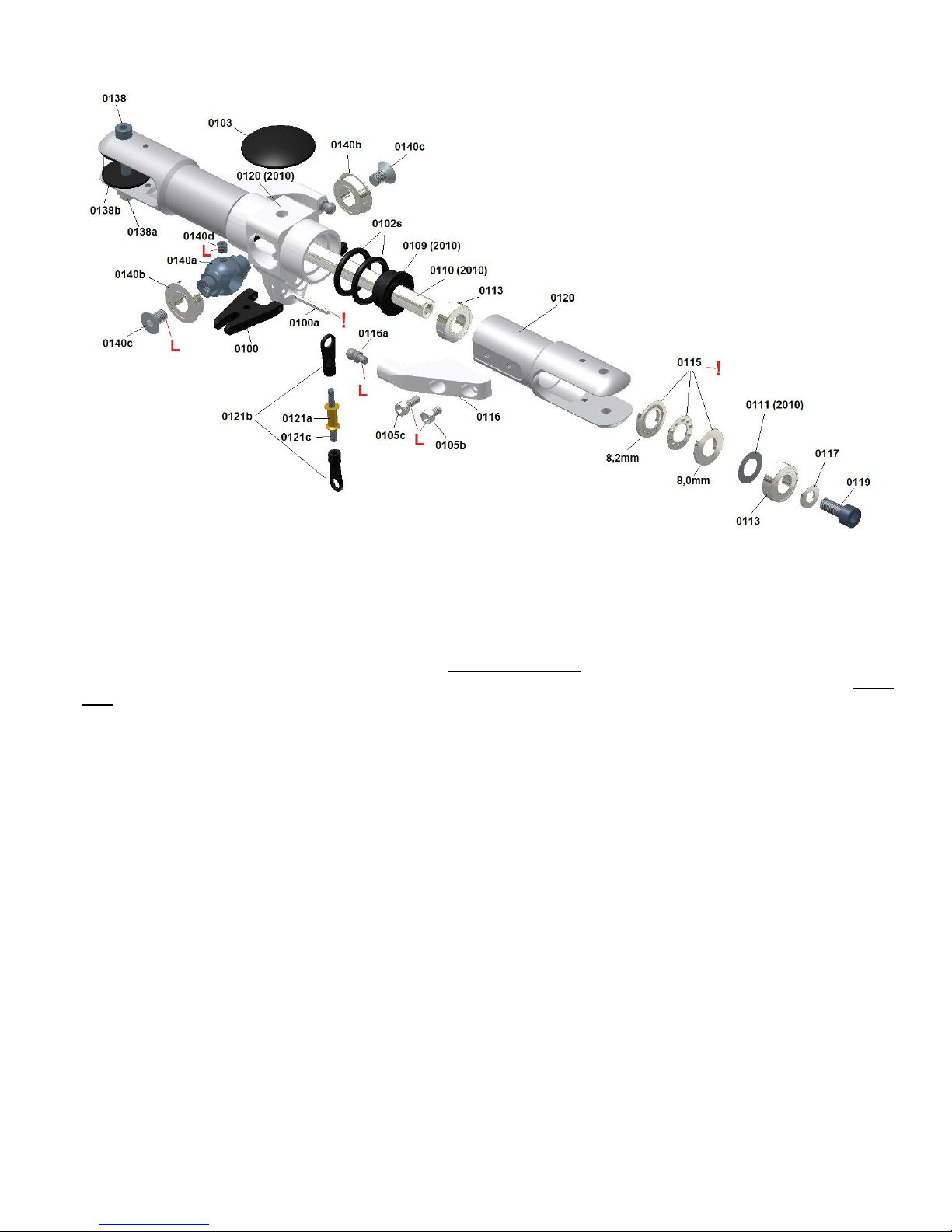
First attach the blade holders to the corresponding bearings. Attention! To avoid mistakes proceed as described below. First
the two inner bearings 0113 showing towards the centre hub are pushed into the corresponding blade holders. It is
recommended to heat the blade holder slightly using a hot air gun. Make sure that the bearing rests rectangular and that it
does not tilt when assembling it. Now attach the thrust bearing from the fork side. First grease the ball cage thoroughly (add
tenacious grease in the hollow side of the sheet cage). Mind the correct order as shown in the drawing. To attach the single
rings in the hole, they have to be inserted at the side and crosswisely into the fork and then they have to be tilted in the
turned recess. Make sure that the rings do not turn by 180° when sliding into the blade holder hole. The corresponding
chamfer must point to the ball cage. It is recommended to insert a thinner stud into the bearing ring hole and to push it into
the blade holder to prevent the rings from turning.
First insert the ring having an inner diameter of 8.2mm into the blade holder. Then attach the ball cage with the hollow side
turned to the 8.2mm ring and at last add the ring with the inner diameter of 8mm. The spacer washer 0111 (0.2x 8x 14) and
then the second radial bearing 0113 are inserted.
Attention! To prevent the second radial bearing from tilting proceed as described below. Provisionally push the feathering
spindle 0110 through the already mounted bearing in the blade holder. Slide the remaining bearing in the fork at the side and
push it onto the end of the feathering spindle. Tighten one of the black M5 screws loosely in the thread of the feathering
spindle and pull the bearing into the hole of the blade holder using the feathering spindle end looking out at the back. It is also
recommended to heat the blade holder slightly.
Due to this measure the bearing cannot tilt or am, because it is aligned to the longitudinal axis of the blade holder by the
feathering spindle. Then remove the feathering spindle and assemble the second blade holder in the same way.
10

At last the blade holder arms 0116 are tightened to the blade holder 0114 using the corresponding screws and Loctite. Before
tightening the screws 0105b and 0105c pull the arms in the play of their holes towards the main rotor centre and make sure
that they rest properly on the bottom of the blade holder cutout. The threaded link ball 0116a is tightened using Loctite.
Attach the O-rings 0102s with the feathering spindle bushings 0109-2010 to the centre hub. Slightly grease the O-rings. Slide
the feathering spindle 0110 into the centre hub. Make sure that the seesaw 0140a is turned such that the grub screw 0140d
points to the top (do not yet thighten the grub screw!).
Push the preassembled bladholder onto the feathering spindle.
It can occur that the blade holder pre-mounted to the bearings cannot be slid on completely although the bearing can be
moved onto the feathering spindle easily. A shifted spacer washer 0111 that has moved and is not located in the middle
prevents it from being moved further. In this case use a stud and centre the washer such that it is aligned to the other holes of
the ball bearing in the blade holder.
Secure the blade holders using the washers 0117 and the screws 0119 (Attention! The black screw 0119 has a great rigidity
and may only be replaced by an original replacement part. Conventional screws may break. After tightening the screws the
blade holders must have centered automatically and they have the same distance to the centre hub. By tilting the seesaw to
the stop the blade holders strike the plastic bushing, so that the feathering spindle is better centered in the middle. If there is
a remarkable axial play, thin spacer washers can be added between the feathering spindle bushing 0109-2010 and the first
bearing 0113. Always use the same size on both sides (in the bag with the O-rings there are two spacer washers 0.2x 8x 14).
Now tighten the grub screw 0140d well from above through the 5mm hole in the centre hub. Use Loctite and slightly cover the
grub.
Attention! Avoid adding Loctite to the threaded hole of the seesaw. Otherwise it is pressed by the grub into the passage hole
for the feathering spindle, which then gets stuck. Such a stuck feathering spindle can hardly be removed later without
destroying other parts.
Attention! Do not yet attach the rotor brake 0103, because the planar supporting area of the main rotor centre hub is needed
as supporting area for a measuring bar to ad ust the blades (see Chapter XIV – Ad ustments).
After the assembly you will notice that the blade holders can be tilted up and down to a minimum extend around the centre of
rotation of the seesaw within the play of the feathering spindle bushing (The bushings are by two tenth of a mm bigger than
the spindle).
With mounted blades and after some flights you can measure about 3-5mm at the blade tips after all parts are set. The rotor
can be tilted without problems by this amount. This is intended and the reason for this construction.
Therefore no vibration pulses of the rotor are transmitted to the fuselage during hovering. Hereby resonances are avoided
and a smooth hovering during all speeds is assured. During intended cyclic control inputs the feathering spindle tilts against
the relatively hard-damped bushings leading to the desired quick reaction of the helicopter.
For pilots who prefer to fly very hard 3D, most of the time with high head speed above 1700 revs there is a option to get a
stiffer damping by changing the black spindle bushings 0109-2010 against white bushings 0109 which have no play.
Therefore the two inner of the black O-rings 0102s should also be changed against two red O-rings 0102r (please have also
a look at the TDR-manual 2009 for more details). In this case sometimes some fuselage resonances have to be accepted
when hovering between 1400 and 1700 revs.
After a crash do not try to pull the feathering spindle through the seesaw by using the deformed side. Take the undeformed
side.
Check the first visible bearing 0113. The other bearings are usually not affected. Use your finger to turn the inner ring of the
bearing and check if it runs smoothly. You can pull this bearing out without having to remove all the other parts from the blade
holder. Push the old feathering spindle only into this bearing and pull it out of the blade holder (if necessary heat blade
holder) by tilting it sidewisely and luffing it slightly. You can also strike the bearing out from the fork side using a spindle of a
thickness of about 6 mm that is positioned diagonally on the inner ring of the bearing. Do not use excessive forces when
hitting the blade holders on the new feathering spindle, if the bearings am. It is recommended to clamp the shaft into a
drilling machine and to treat it carefully with a strip of sandpaper.
Attention! Do not use any other feathering spindle for the Rigid 2010 than the original feathering spindle RI-0110 (2010)
delivered by me. This spindle is inductively surface hardened and was spheroidised on both threaded sides to avoid the
danger of hardening cracks in this area with a low diameter. Due to the seesaw bearing the spindle is exposed to higher
forces. These are lower when using a conventional bearing with bending points at a greater distance from each other.
Therefore a normal soft spindle like the one I have used before will be deformed even at low flight loads. However, this
spindle can also be deformed due to certain flight manoeuvres. Avoid extreme pull-out manoeuvres during high air speed,
especially in combination with a low head speed. In this case the centrifugal forces are not yet sufficient to take load from the
feathering spindle and prevent it from bending.
The connecting rods 0121c are mounted according to the drawing. At first turn the 15mm ball links 0121b to the brass
bushing 0121a until they reach the stop. Then turn them, so that they are positioned at an angle of 90° to each other. This
can be facilitated by greasing the threaded rod. In the ideal case the imprint 2,5 is positioned, so that it points to the outside
during the assembly to the threaded link ball of the blade holder arm and the swashplate (lower forces are then necessary to
assemble the link). It will be fine-ad usted later during the ad ustment of the blades.
11
Chapter – II M a i n s h a f t u n i t ( Assembly Group 4 )
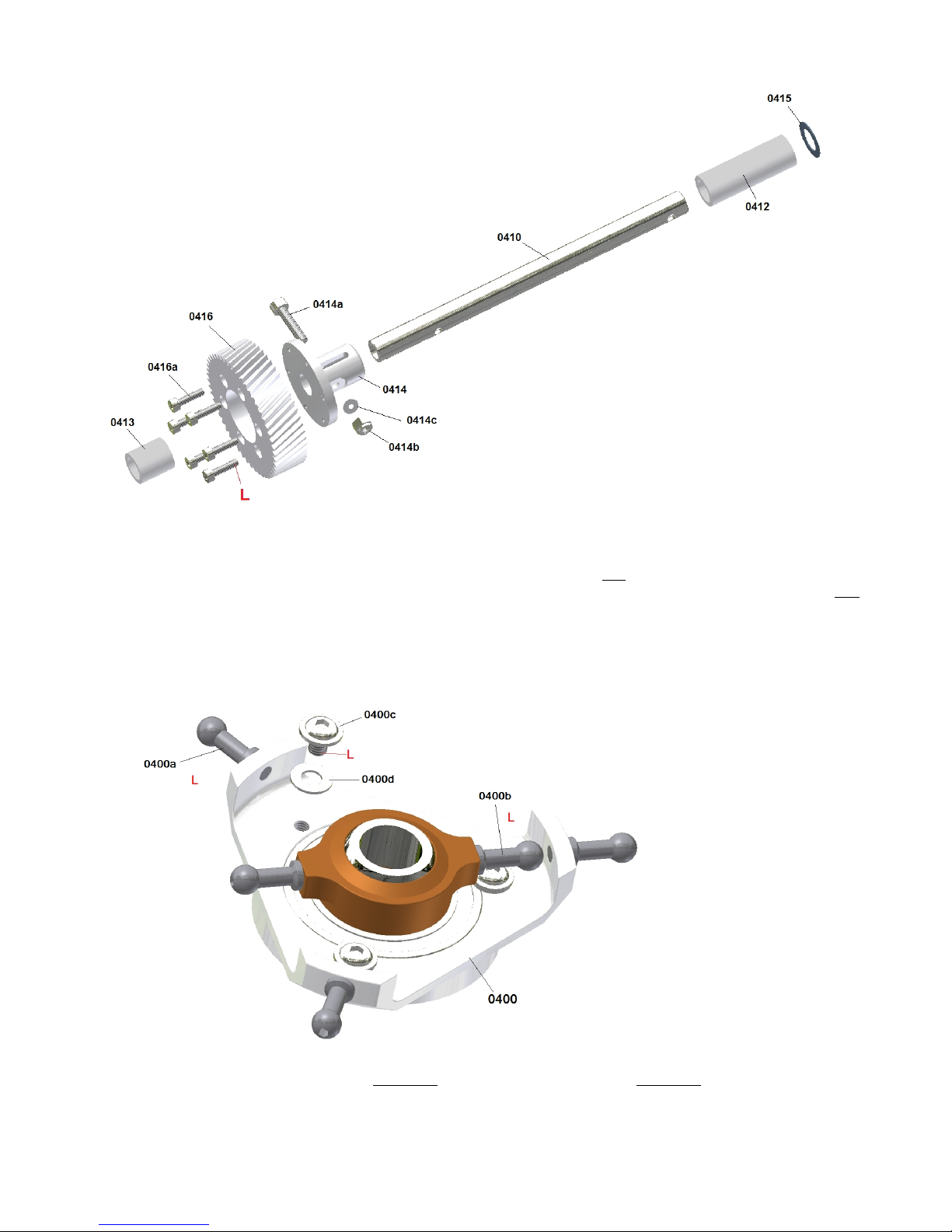
Note that you tighten the screws carefully, evenly, step-by-step and crosswise when mounting the main shaft gear 0416 to
the flange 0414 in order to avoid uneven tension to the gear. In this case Loctite has to be used.
Slide the part onto the main shaft according to the drawing and tighten the screw 0414a and the nyloc nut 0414b well (use
90° offset allen wrench and wrench socket to provide sufficient forces). The flange is to stay in position due to the friction and
not by shear of the screw!
Do not forget the 0.5mm strong spacer washers on the upper end and put the unit away for the time being.
Tighten the threaded link balls 0400a (with a 3mm long M3 thread) and 0400b (with a 4mm long M3 thread) at the swash
plate use Loctite. Also the M3x 6 domehead screws 0400c has to be tighten with Loctite to secure the big ball bearing of the
swash plate. Don´t forget to put the 3mm washers 0400d underneath the dome head.
12
Chapter – III I n t e r m e d i a t e s h a f t u n i t ( Assembly Group 5 )
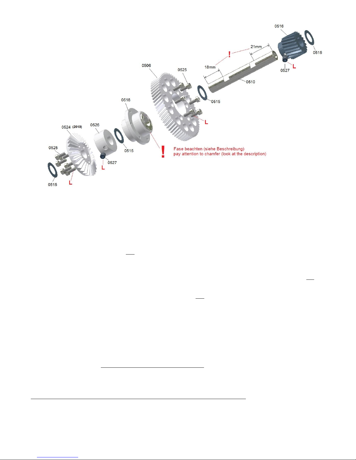
Attention ! At first you have to decide whether you wish to build a right-hand rotation system as drawn in the manual or a
left-hand rotation system (looking onto the helicopter from above = right-hand rotation system rotates clockwise / left-hand
rotation system rotates anti-clockwise).
It depends on the chosen system which way round you mount the one-way drive flange 0518 to the gear wheel 0506. The
almost symmetric flange has a noticeable chamfer on the one side. Put the flange with the chamfered side into the gear hole
as described in the drawing to get a right-hand rotation system.
If you wish to build a left-hand rotation system put the other side without the large champfer into the gear hole.
Note that you tighten the screws carefully, evenly, step-by-step and crosswise during assembly, in order to avoid uneven
tension to the gear. In this case Loctite has to be used.
Attention! When attaching the crown gear 0524 to the driving disk 0526 proceed as described below to achieve an optimal
rotation. First slide the disk provisionally on the intermediate shaft and tighten it using the grub screw 0527 (do not yet use
any Loctite). Make sure that the grub screw ams the flat area of the shaft. Now slide the crown gear 0524 onto the shaft until
it reaches the disk and align it according to the attachment threads to tighten it. Tighten it carefully, step-by-step and
crosswisely to avoid tension to the crown gear. In this case Loctite has to be used. After having tightened the crown gear to
the disk you can loosen the grub to remove the unit from the shaft again.
During this proceeding the crown gear is optimally aligned to the disk. This way it will be positioned at the final assembly. Due
to the pressure of the grub screw the disk is not positioned completely centrically and the attachment threads do not allow for
an exact position. If the crown gear is mounted after having been fastened as described, it is aligned exactly during the final
assembly and runs absolutely smoothly.
Now mount the intermediate shaft pinion 0516 on the intermediate shaft 0510.
Attention ! The distance between the grub screw contact areas and the corresponding end of the shaft is different. The side
with the larger distance of 21 mm is mounted to the top in the direction to the pinion (see drawing). The M5x 5 grub screw
0527 of the pinion is tightened well using a small amount of Loctite. Move the pinion on the shaft in the grub screw contact
area play such that the shaft looks out at the top of the pinion by 6.5mm before tightening the grub screw using an L-key.
Attention ! Please apply Loctite only on the side of the thread of the grub screw but not to the hole of the pinion. Otherwise
the Loctite is pressed through the thread hole on the shaft. This would make a later disassembly extremely difficult!
Finally, slide all pre-mounted flanges and the four 0.5mm spacer washers 0515 on the shaft according to the drawing and
tighten the M5x 5 grub screw of the driving disk 0526 only loosely without using Loctite, so that the driving disk has not any
axial play.
Later during the ad ustment of the gear play the position of the driving disk will possibly have to be changed using the
corresponding spacer washers. Thus, the grub screw will finally be secured and tightened.
Then put the unit aside.
13
Chapter – IV T a i l b o o m ( Assembly Group 8 )
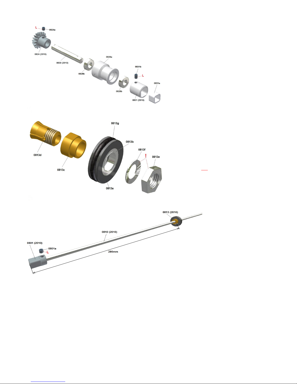
The 5mm drive tube 0810 have a total length of 852mm. Brass pins with a length of about 18 mm are glued to both sides, so
that the grub screw 0801a of the square headed coupling 0801 does not press the tube together. At first slide the prepared
bearing 0813 from one side on the shaft, so that the clamping slots point towards the outside to the end of the shaft. Thus the
unit can be moved more easily. If you did it the other way round, the collet would be pressed into the cone of the bearing
bushing and some parts might am. Position the bearing as shown on the drawing at a distance of about 280 mm from the
front side of the drive shaft to the front side of the collet. Now you need a 13mm flat wrench for the nut 0813e and an 11mm
flat wrench for the spanner flat of the bearing bushing 0813c.
Attention! Only tighten the nut with your hand (do not use the flat wrenches), so that the nut rests tightly on the circlip (do as
much as you can with your hands. Do not use a tool). Then the nut is tightened by 120° using the two flat wrenches. This
exactly corresponds to 2 spanner flats (1/3 rotation). If you proceed as described, you will get the exactly correct tightening
torque for a secure position of the unit. If you tighten the nut further the thin-walled drive shaft tube may be pressed together
or the thin-walled collet 0813d may even break away.
Now attach the square headed coupling 0801 according to the drawing (front edge flush with the tube) and tighten the grub
screw 0801a firmly using Loctite. Use the high-quality L-key to apply a sufficiently high force. The grub is to be pressed
slightly into the inox steel tube to assure a secure connection that does not slip during operation (do not use any grubs with
knife edge seals, because that have not proven their worth).
Proceed the same way with the second bearing and the second square from the other side of the tube. Then put the units
aside.
14
The two ball bearings 0828b are pressed into the
bearing flange 0828a until they are flush with the
flange. The clutch insert 0831a is pressed into the
clutch 0831. At first slide the clutch on the shaft 0830
until it reaches the stop and tighten it using the grub
screw 0831b (M4x6). Then push the shaft into the
bearing support, so that the clutch rests completely
on the rear bearing. At last the conic pinion 0824 is
slid from the front onto the other side of the shaft
until it reaches the stop and tightened using the grub
screw 0824a (M4x4), so that the shaft has not got
any axial play. Only cover the grub screw with
Loctite and avoid covering the threaded hole. If the
shaft does not run smoothly after having tightened
the grub, loosen the grub again and pull the pinion
slightly to the front, so that there is no axial tension
applied to the bearings.
Push the bearing 0813b with the bearing support
0813a onto the bearing bushing 0813c. The collet
0813d is inserted into the bearing bushing.
Attention! Slide the locking washer 0813f onto the
collet, so that the bottom of the washer only presses
against the inner ring of the bearing. Do not position
it the other way round, so that the outside of the
washer presses onto the outer bearing ring or the
bearing cover (when tightening the nut the bearing
would am). The nut 0813e is only tightened loosely
to the first thread pitches of the collet.
Attention! Do not use Loctite. The collet would slip in
the bearing bushing during loosening the tight nut.
So the nut cannot be removed any more, because
you cannot hold the collet.
The bearing 0813 and the square
headed coupling 0801 are added to
both sides of the drive shaft 0810 as
described below. The bearings are
attached to the shaft and not
ammed in the tail boom any more.

Chapter – V h a s s i s ( Assembly Group 2 )
Pre-assembly of the upper part of the chassis
(Bag 2-I) Put the bearing supports 0221/0222 with their bearings 0223 on the already pre-mounted intermediate shaft unit
and main shaft unit, such that the bearings looking out of the one side of the support point to the gears !
The bearings of the lower supports point to the top - and the bearings of the upper supports point out to the bottom. At first,
tighten the units with the bearing supports loosely on a chassis side-frame plate as shown on the drawing (do not yet tighten
the screws).
Attention! one of the plates has got a bigger gap on one side which is marked with a black cross. This plate has to be used as
upper support for the intermediate shaft 0510 with the marked side to the front in direction to the motor.
Attention! Use the dome head screws 0254 without the additional washers for the front hole of the upper main rotor shaft
frame plate. For all other holes small M3 washers 0257 and M3x 8 caphead screws 0255 are used (for all these screws
Loctite is not necessary).
(Bag 2-II) At first one M3 nyloc nut 0237c is tightened using Loctite on only one side of three M3 threaded rods 0237a for the
tail boom holders, so that the threaded rod protrudes from the nut by approx. 0.5mm. Later, this nut shall not turn when
loosening or tightening the opposite nut to attach the tail boom. Otherwise the threaded rod protrudes unevenly on one side.
Now push three of the prepared threaded rods through the corresponding holes from the outside using a large M3 washer
(according to drawing). The canopy mount 0236 is added to one side of the fourth threaded rod, which is then moved through
the rear upper hole of the chassis without using a washer.
Attention! During the assembly of the tail boom holders note that the clamping slots point down.
Now assemble the second frame plate from the second side. Place the lower edge of the frame plates of the mechanics on
an even ground and alternately tighten the screws only slightly at first.
Attention! If the vertical distance of the frame plate holes of the pre-mounted shaft unit is larger than the distance of the
chassis side-frame plate holes, the upper 0.5mm spacer washer under the upper frame plate has to be replaced by thinner
spacer washers from the enclosed bag with the additional spacer washers.
The lower nuts of the tail boom holders are screwed only loosely on the threaded rod, but not yet tightened!
Adjustment of the axial play of the main rotor shaft
At first, the axial play of the main rotor shaft is removed by adding spacer washers (can be found in the corresponding
assembly group bag) between the upper frame plate and the spacer 0412.
In order to do so, push the rotor shaft with the gear completely to the bottom against the bearing of the lower frame plate and
measure how far it protrudes from the top of the upper frame plate using a depth gauge of a calliper.
15

Then pull the shaft in the play against the upper bearing and measure again, how far the shaft protrudes now. The difference
of both measurements represents the amount you have to add – in the form of spacer washers – between the upper bearing
and the spacer. Only unscrew the upper frame plate once again and pull it to the top and out of the mechanics, to slide the
spacer washers onto the rotor shaft. Then re-mount the plate again check for the play again.
A minimum play of one tenth mm has not any negatives effects. Anyway, after some flight hours it can be necessary to check
the entire system and to ad ust it by adding further spacer washers, if the unit has set.
Adjustment of the axial play and assembly height of the intermediate shaft
For the intermediate shaft proceed in the way as for the rotor shaft. However please note that the steel pinion 0516 is
positioned in the same height than the main rotor shaft gear 0416. According to this, you can add spacer washers underneath
the upper frame or above the crown gear flange 0526, until it suits well.
If it is necessary to put thinner than the 0,5mm washers above the steel pinion 0516 you have to add the difference between
this pinion and the one way bearing flange 0518 so that the position of the gear wheel 0516 is not to high in the gap of the
frame to prevent a contact.
Fill up the other gaps between the different flanges with additional washers until there is no axial play any more in the unit.
Attention ! the grub screw of the crown gear flange and the screws of the lower bearing support from the intermediate shaft
unit is still not finally tightened yet).
Then place the mechanics again on an even surface and tighten the screws of all frame plates well (excluding the lower
frame plate of the intermediate shaft).
Only the upper screw of the two tail boom holders is tightened slightly.
Adjustment of the gear play and the pinion position of the tail drive
At first, press the already prepared tail boom through the two tail boom holders, until the pinion is positioned above the crown
gear such that the two edges congruently create a parallel line (see yellow lines).
If the tail boom ams in the front aluminium holder, grease it a little and force its slot apart using a screw driver (put it into slot
and turn it).
If the tail boom cannot be inserted far enough, because the teeth of both gears already contact, you have to unscrew the
lower bearing flange once again and put correspondingly thinner spacer washers below the crown gear to give it a lower
position. According to this, you have to compensate for the difference above the crown gear flange the by adding spacer
washers, in order to avoid an axial play of the intermediate shaft.
Attention ! You have to try several times. So you have to mount the lower frame plate provisorily to the attachment screws
again and again to prevent the intermediate shaft from tilting to one side and from being positioned in an inclined way. The
plate can easily be pulled down and removed from the mechanics.
This way you find the correct combination of spacer washers above and below the crown gear flanges with its crown gear
until you notice a small play between the teeth edges (you hear a low ticktack when turning at the pinion) when turning the
pinion and holding the crown gear.
Always turn the crown gear some teeth further and thus check the play at different positions. There are always certain
tolerances and you will notice a smaller or larger play at different positions. It is important that every position has a certain
play and that there is not any position without a play. Now you can tighten the screw of the lower frame plate and the grub
screw of the crown gear flange. Please ensure that the grub screw is positioned on the flat area of the intermediate shaft.
Attention ! Please apply Loctite only on the side of the thread of the grub screw, but not to the hole of the flanges. Otherwise
the Loctite is pressed through the threaded hole on the shaft. This would make a later disassembly extremely difficult!
16
First mount the preassembled bearing flange
0828a (see page 14) with the two M3x6 screws
at the front of the boom (short distance from the
centre of the hole to the front edge of the boom).
Than ad ust the right gear play.
No play, a too small play or the wrong positioning
of the pinion in relation to the crown gear (tail
boom is pushed in too far or not far enough) can
lead to increased noise emissions and to
vibrations in the entire drive, which can result in
vibrations around the vertical axis or negative
influences on the V-Stabi sensors. The entire
helicopter will then hover nervously.
Too much play mostly leads to increased
operating noises.
Therefore, ad ust the gear play and the pinion
position diligently (see description).
In order to facilitate the handling during a later assembly, the tail boom can now be pulled out. To find the correct tail boom
position it is recommended to wind some fabric tape around the tail boom ust behind the rear tail boom holder 0233. It serves
as stop mark when re-inserting the tail boom (never mark the boom with a sharp knife or something like that).
If you wish to correct the gear play later during the operation, you can ad ust the tail boom axially to the front direction by
approx. 0.5 mm at maximum. So you do not always have to use spacer washers. This value should not be exceeded.
Otherwise the teeth geometry is not optimally aligned any more.
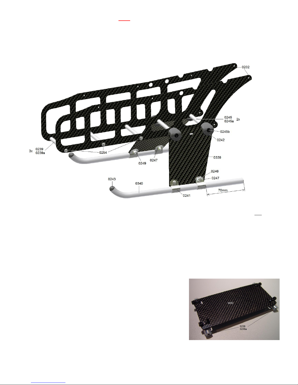
Pre-assembly of the lower part of the chassis
(Bag 2-III) Attach the two (lower) frame plates 0202 to each other using the three 62mm studs 0239 covered with the silicon
tube 239a. In order to do so, use the lens head screw with a flange 0254 according to the drawing (do not use any Loctite).
The other studs and parts of this bags are not yet needed.
(Bag 2-IV) Mount the skids 0340 with the skid clamps 0241 as well as the attachment screws 0246 (cross recess M3x8), the
large M3 washers 0247, the M3 nyloc nuts 0249 to the skid plates so that the screw heads look to the outside. The skid is to
protrude by 70mm from the rear skid clamp. Do not yet tighten the nuts in order to be able to align the skids.
Position the two 62mm studs 0245 (with M4 thread) covered with the silicon tube 0245a between the two chassis frame
plates according to the drawing.
Now the plastic holders 0242 are put onto the skid plates and screwed to the studs using the black M4x20 screws 0245b.
Align the skids such that the tips are directed vertically to the top and tighten all the screws well.
17
Mount the controller supporting plate 0252 to two 58mm studs 0238
covered with the silicon tube 0238a (bag 2-III) using some cable ties.
Please note that the plate is aligned such that is it positioned in the centre
and that the closures of the cables ties point to the top but not to the
bottom. Otherwise it will hinder the battery from being inserted below the
stud.
The cable ties can be found in the bag (Other Parts).
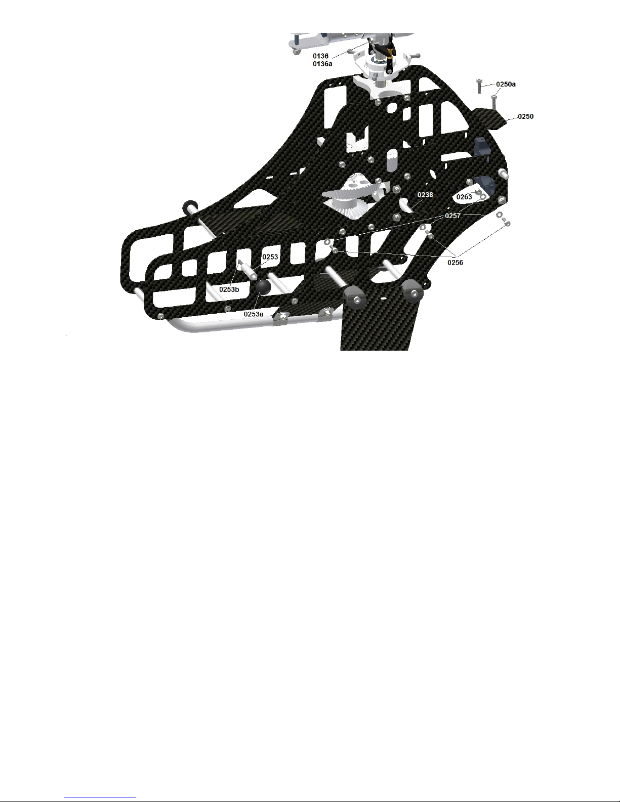
Assembly of the upper part to the lower part of the chassis
Put the prepared controller supporting plate between the two side-frame plates of the upper part of the chassis according to
the drawing. The remaining third stud 0238 is positioned between the free holes ust behind the front tail boom holder.
Widen the two side-frame plates of the lower part of the chassis at the top such that it can be slipped over the lower edge of
the upper part of the chassis. The plates have to be widened such that the two large holes at the upper edge of the lower part
of the chassis can be positioned above the screw heads of the already mounted lower frame plate of the intermediate shaft.
Tighten the upper and the lower part on both sides to the 58mm spacers using the three M3x10 screws 0265. The rear screw
is tightened from the inside using a washer 0257 and a M3 nyloc nut 0263 because there is no spacer provided.
The front spacer of the controller supporting plate is tightened using the two front canopy mounting bolts 0235. For that
purpose at first screw the M3x 16 stud bolts 0253b into the canopy mounting bolts using Loctite and then attach them to the
front spacer of the controller supporting plate. To tighten the canopy mounting bolt you can use a 7mm flat wrenche.
Then the two rubber end caps are attached to the ends of the canopy mounting bolts. These caps fit exactly in the
circumferential canopy edge so that they keep their correct position.
(Bag 2-V) Assemble the sensor bottom plate 0250 on the rear tail boom holder using the two M3x12 screws. Tighten the
screws carefully in order not to destroy the hole in the plastics. Finally, the swash plate can be slid onto the rotor shaft (using
some glutinous grease and never thin oil).
The main rotor can be tightened using the M4x 18 shaft screw 0136 and the M4 nut 0136a.
Attention! This has to be tightened well using a 90° offset allen wrench so that the centre hub is clamped on the rotor shaft
and the screw is not submitted to shear strain. When the centre hub on the rotor shaft moves during a flight with a loose
screw there is the danger that the rotor shaft as well as the centre hub holes are widened. The result is that the centre hub
cannot be removed from the rotor shaft any more and in extreme cases the screw of the shaft may shear because of the
changing vibrations.
18

Chapter – VI R p r e p a r a t i o n ( Servos )
At first the metal protective sleeves for the screws are pushed through the damping rubbers of the swash plate servos from
below and of the tail rotor servo from above.
Attention! When using the tail rotor servo make sure that a possible stiffening rib on the upper side is flattened such that it
does not protrude from the rubber dampings. The reason for this is that this side of the tail rotor servo later is mounted to the
attachment blocks.
In addition, it is recommended to shorten the cable of the tail rotor servo which is much too long to a suitable length of 70mm
from the servo housing to the end of the plug. In order to do so, cut the Futaba BLS 251 cable at a distance of 30mm to the
housing and completely remove the black insulation. Also shorten the cable with the plug such that 30mm protrude from the
plug and re-solder the 3 strands (at first cover the single strands with a shrinking tube). Also from the plug the black insulation
has to be remove so that the cable is at flexible as possible.
Attention! This procedure is necessary specially when using Mini V-Stabi or something similar if the sensors are includet in
one box with the rest of the electronic so that all the cables from the servos and receiver enter this box. If the cables are to
stiff or connected with cable ties they will transfere vibrations direct into the box which cause problems later during flight.
Look for further informations in Chapter XI for instance if you want to use a sattelite receiver.
Connect the swash servos directly to a free receiver channel (but not to the carb. or the pitch channel. Switch on the
transmitter. Neutralise all trim and sub-trim settings and all programmable mixers should be deactivated so that there is a
neutral pulse at the receiver channel and the servo takes its centre position (this is not possible with the tail servo).
The installation has to be switched on when attaching the single servo arms to the multiple teeth shaft of the servo, so that it
is positioned at right angles to the housing. Please note the different alignment of the single servos in the image. It is
recommended to position the servos according to the drawings and mark them to avoid mistakes during the assembly in the
chassis.
If you have chosen the Futaba BLS 451 Servo recommended by me, I strongly recommend to use the enclosed thick 3mm
servo arms. These arms are sufficiently stiff and the servo gear remains undamaged during a crash. When using aluminium
arms the gear is nearly always defective.
The uneven number of teeth of the multiple teeth unit leads to a slightly different position during the rotation of the servo arm
by 180 degrees. That is how you can improve the rectangularity, if it was not optimal at the first positioning.
Try to find a positioning as good as possible and remove the unnecessary arms of the servo arm. Smooth the edges (this
works best on a sanding machine) as shown in the drawing above.
(Bag 6-I) Attach the threaded link balls 0638 according to the drawing to the three swash plate servos from the lower side of
the arm and secure them on the upper side of the arm using the nuts 0638 (use Loctite).
The distance should be between 16mm and 18mm from the centre of rotation. The Futaba arms have an optimal value of
17.5mm.
For the tail rotor servo you have to use a normal 2mm plastic arm with a 1.5mm hole. The reasons for it is that a metal clevis
is provided which may never be used with an aluminium or carbon arm, because it is directly mounted into the 1.5mm hole.
The optimal mounting point is at 10mm – 11mm from the centre of rotation of the servo. This relatively low distance is
necessary because the transmission ratio at the tail drive is 1:1 in contrast to the one of most of the helicopters. Thus at the
front servo a smaller way is sufficient.
19
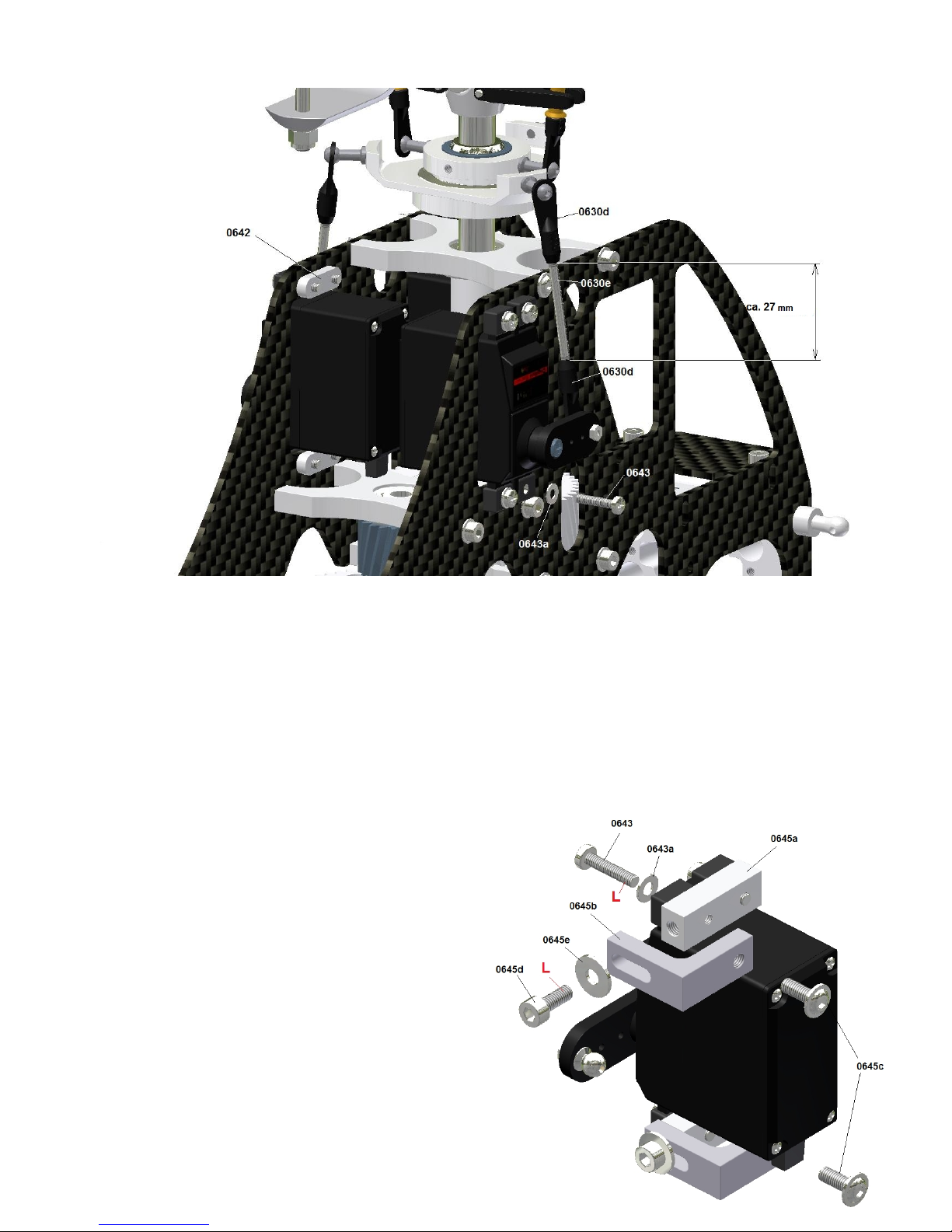
Chapter – VII o n t r o l & S e r v o A s s e m b l y ( Assembly Group 6 )
Assembly of the cyclic servo
(Bag 6-II) At first, use thin double-sided tape to attach the four servo attachment plates 0642 on the inside of the side-frame
plates of the chassis such that they are aligned to the holes. This facilitates the servo assembly considerably.
According to the drawing the cyclic servos are pushed from the outside through the cut-outs of the chassis frame plates with
the cable pointing to the bottom and screwed using the M2,5x12 cross-head screws 0643 and the washers 0643a.
(Bag 6-I) Mount the ball links 0630d on the two 45mm rods 0630e such that a distance of approx. 27-28mm remains between
the front sides. Turn the ball links so that they are positioned at right angles on the ball of the servo and the swash plates and
that the writing (2,5) points to the outside. It is difficult to press the ball link on the ball the other way round. The rods are fine-
ad usted later.
Assembly of the fore & aft cyclic servo
20
At first attach the two fore & aft cycli servo supports 0645a to
the servo according to the drawing using the M2.5x 12
cross-head screws 0643.
The support framing squares 0645b are at first tightened
loosely to the supports.
The elongated holes are used later to ad ust the servo at the
side, so that the threaded link ball of the servo arm is
positioned exactly in the centre in the chassis.
It is intended to lead the fore & aft cyclic rod later as
vertically as possible through the swash plate anti-rotation
guide 0616 (see following page).
Use the two lens head screws 0645c to tighten the angles
loosely to the provided holes of the right frame plate of the
chassis.
Table of contents
Popular Toy manuals by other brands

TP
TP Wooden Potting Bench Instructions for assembly, maintenance and safe use

LeapFrog
LeapFrog Blue's Clues & You! Play & Learn Maracas Parents' guide

Eduard
Eduard 49 287 instruction sheet

QuiQue's Aircraft
QuiQue's Aircraft Semi Scale Yak-54 Assembly manual

Staufenbiel
Staufenbiel WE CAN FLY instruction manual

roco
roco 7100001 operating manual


