manuals.online logo
Brands
  1. Home
  2. •
  3. Brands
  4. •
  5. QuiQue's Aircraft
  6. •
  7. Toy
  8. •
  9. QuiQue's Aircraft Semi Scale Yak-54 User manual

QuiQue's Aircraft Semi Scale Yak-54 User manual

Other manuals for Semi Scale Yak-54

2

Other QuiQue's Aircraft Toy manuals

QuiQue's Aircraft Yak-54S User manual

QuiQue's Aircraft

QuiQue's Aircraft Yak-54S User manual

QuiQue's Aircraft Yak-54S User manual

QuiQue's Aircraft

QuiQue's Aircraft Yak-54S User manual

QuiQue's Aircraft 102" YAK 54 Installation guide

QuiQue's Aircraft

QuiQue's Aircraft 102" YAK 54 Installation guide

QuiQue's Aircraft Semi Scale Yak-54 User manual

QuiQue's Aircraft

QuiQue's Aircraft Semi Scale Yak-54 User manual

Popular Toy manuals by other brands

FUTABA GY470 instruction manual

FUTABA

FUTABA GY470 instruction manual

LEGO 41116 manual

LEGO

LEGO 41116 manual

Fisher-Price ColorMe Flowerz Bouquet Maker P9692 instruction sheet

Fisher-Price

Fisher-Price ColorMe Flowerz Bouquet Maker P9692 instruction sheet

Little Tikes LITTLE HANDIWORKER 0920 Assembly instructions

Little Tikes

Little Tikes LITTLE HANDIWORKER 0920 Assembly instructions

Eduard EF-2000 Two-seater exterior Assembly instructions

Eduard

Eduard EF-2000 Two-seater exterior Assembly instructions

USA Trains EXTENDED VISION CABOOSE instructions

USA Trains

USA Trains EXTENDED VISION CABOOSE instructions

Modellbau Laffont Z1601 Assembly instructions

Modellbau Laffont

Modellbau Laffont Z1601 Assembly instructions

NOCH 12905 instruction manual

NOCH

NOCH 12905 instruction manual

Eduard Ki-61-Id quick start guide

Eduard

Eduard Ki-61-Id quick start guide

Viessmann Vollmer 45616 Mounting instruction

Viessmann

Viessmann Vollmer 45616 Mounting instruction

Vollmer 42004 Mounting instruction

Vollmer

Vollmer 42004 Mounting instruction

Phoenix Model CLASSIC-EP instruction manual

Phoenix Model

Phoenix Model CLASSIC-EP instruction manual

H-KING Sopwith Camel British WW1 Fighter instruction manual

H-KING

H-KING Sopwith Camel British WW1 Fighter instruction manual

MODSTER Predator 4x4 Crawler user manual

MODSTER

MODSTER Predator 4x4 Crawler user manual

DHK Hobby 8136 User instruction manual

DHK Hobby

DHK Hobby 8136 User instruction manual

THUNDER TIGER Raptor 50 V2 kit manual

THUNDER TIGER

THUNDER TIGER Raptor 50 V2 kit manual

Timberkits Skateboarder instructions

Timberkits

Timberkits Skateboarder instructions

Hangar 9 Funtana 125 Assembly manual

Hangar 9

Hangar 9 Funtana 125 Assembly manual

manuals.online logo
manuals.online logoBrands
  • About & Mission
  • Contact us
  • Privacy Policy
  • Terms and Conditions

Copyright 2025 Manuals.Online. All Rights Reserved.

Semi Scale Yak-54, ARF 101”
ASSEMBLY MANUAL
Specifications
Wingspan: 101 in
Length Including Spinner: 91 in
Wing Area: 1,960 sq in
Weight (RTF): 24.5-25.5 lb
Recommended Engines:
Gas 80-85cc
Quique’s Aircraft Company
3410 Saint Paris Pike
Springfield, OH 45504
Phone: (937) 629-0339
Fax: (937) 629-0335
Email: [email protected]
Website:www.QQAircraft.com
Online-Support:http://www.rcuniverse.com/forum/forumid_437/tt.htm
Quique and I want to express our thanks to you for choosing our 101” Yak-54.
We think that you will enjoy one of the best flying model aerobatic airplanes
available. It is patterned after the 37% Yak-54 which took First Place honors at
the 2003 Free Style Championships in Lakeland Florida, First Place at the Don
Lowe Master competition 2003 & 2004, First Place Tucson Shoot Out 2004 Free
Style, First Place XFC 2004, precision and free-style and Third Place at the
Tournament of Championships in Las Vegas in 2002.
Quique and I have tried to prepare the best assembly manual possible along with
best support on our line of Aircraft. We are happy to announce that we have a
support forum on www.Rcuniverse.com that is being led by
Mr. Reza Gholamipour. Imagine, you are building your plane during the weekend
when we are closed and you desperately need to get an answer to your question
to continue building. Well we are happy to tell you that your question has most
likely already been asked and answered on the RC Universe forum “QQ Aircraft
Support.” If not, just post your question on the most appropriate thread and have
the answer in matter of hours.
Good flying to you!
Quique & Wayne
Covering Colors
Ultra-cote covering used on this 101” Yak-54 can be purchased from Horizon
Hobbies Website. The codes are as follows:
Midnight Blue Hanu885
Silver Hanu881
White Hanu870
Dark Yellow Hanu889
Going Over the Covering
Before beginning the assembly of your Yak-54, remove each part from its bag for
inspection. If you find any wrinkles in the covering, use a heat gun or covering
iron to remove them. Use caution while working around areas where the colors
overlap to prevent separating the colors. Make sure you go over the edges with
your iron as well.
Hardware Supplied
Pull/Pull Rudder
Wing pins/clips aileron push rods
Tail Wheel
Elevator Titanium rods & ball links pins
Fuel Tank
Canopy hardware
Cowl hardware
Optional Dubro Hardware to complete your Assembly:
Wheels and Axles
Control Horn System
Additional Required Tools and Adhesives
•Covering/Trim iron
•Xacto knife, #11 blade
•Pacer hinge glue (PT-55)
•5,30-minute epoxy
•Lithium grease
•Acetone/Alcohol swabs
•Pencil and Marker
•Ruler
•Drill
•Drill bit 1/16”,1/8”, ¼”, 3/16”, #33, #25, #54
•Wire cutter
•Course and fine sandpaper
•Thin, medium and thick C/A
•Full threaded servo mounting screws
•Pliers
•Masking tape
•Ultra fine point sharpie
•Double-sided tape
•Rat-tail file
•Thread Locker
•Clear Silicone
•Clear packing tape
•C clamp
Extensions:
•(2) 24” and (2) 3” servo extensions for Ailerons
•(2) 48” servo extension for Elevators
•(1) 24” servo extension for throttle
•(2) 12” servo extension from Aileron matchbox to Receiver
All Other Parts Required to Complete the Aircraft
•DA-85 or similar engine
•(7) JR 8711 or similar Digital servo
•(1) JR 4721 or similar analog servo
•(4) 1.5” and (2) 1.25” single side Aluminum servo arms and (1) 3” double side aluminum
servo arm for all control surfaces. (1) Plastic servo arm for throttle.
•(2) 2300 mah A123 Duralite battery or similar for Receiver
•(1) 2150 mah Li-Ion Duralite plus battery or similar for ignition
•(1) AR 9100 DSM2 PowerSafe Receiver or similar
•(1) Duralite digital switch with built-in 5.5v regulator for ignition (P/N #80401) or similar
•(1) 4 ½” Tru-Turn P-51 style spinner or similar
•(1) Mejzlik 26x12 2-Bladed Prop or similar
Servo Selection
The servos used for the control surfaces of this Yak-54 are as follows:
Ailerons (4), JR 8711
Elevator (2), JR 8711
Rudder (1), JR 8711
Throttle, any standard analog servo
Make sure you use same or equivalent torque servos that are digital.
Please do not risk your plane by using low torque or analog servos.
This Yak-54 has large control surfaces and fully capable of any maneuvers that a pilot is able to
perform. Therefore, using weak servos will increase chance of flutter and may result in a crash.
Using the Manual
This manual is divided into sections to help make assembly easier to understand and to provide
breaks between each major section. Remember to take your time and follow the directions.
Warning
I am sure that for the most of you this is not your first venture into the World of flying radio-
controlled aircraft. For those of you that may be entering this exciting sport early on in your
modeling experience and for you with vast experience, I think we all need to be reminded of the
possible dangers that are associated with a high performance aircraft of this type. This is not a
toy. This aircraft must be flown in a safe manner at all times. You should always do a preflight
check including control surfaces hook-ups, radio operation, (please refer to your radio equipment
instruction manual for range checks and other pertinent related information) and all other checks
relating to the safe operation of this aircraft.
Warranty Information
Quique’s Aircraft Company guarantees this kit to be free from defects in both material and
workmanship at the date of purchase. This warranty does not cover any parts damaged by use or
modification. Please inspect all the components and parts immediately upon receiving the aircraft.
You must notify QQ Aircraft Co. within 15 days of the receipt of your shipment and report any
damaged components or parts or this warranty will be considered void. Do not proceed with
assembly until you have contacted QQAC and all possible issues with damaged parts have been
resolved. Customer will then have 3 months to report any problems that he/she may discover
during assembly; this only applies to any manufacturing defects that may be discovered during
assembly. This Warranty extends to the original purchaser only and will be honored with the
original sales receipt. In no case shall QQAC’s liability exceed the original cost of the purchased
kit.
QQAC will keep spare parts in stock for the purchased aircraft up to 18 months after the product
is discontinued.
Please make sure to direct all/any warranty requests to QQAC directly by email with pictures
(preferred method) [email protected] or phoning QQAC at 937-629-0339.
Preparing the Fuselage
Required Tools and Adhesive
•Xacto Knife, #11 Blade
•Sealing Iron
•Fine line Marker
•Medium CA
Preparing Fuselage
In this step, we are going to remove
covering from the Fuselage which will allow
access for different components in coming
steps.
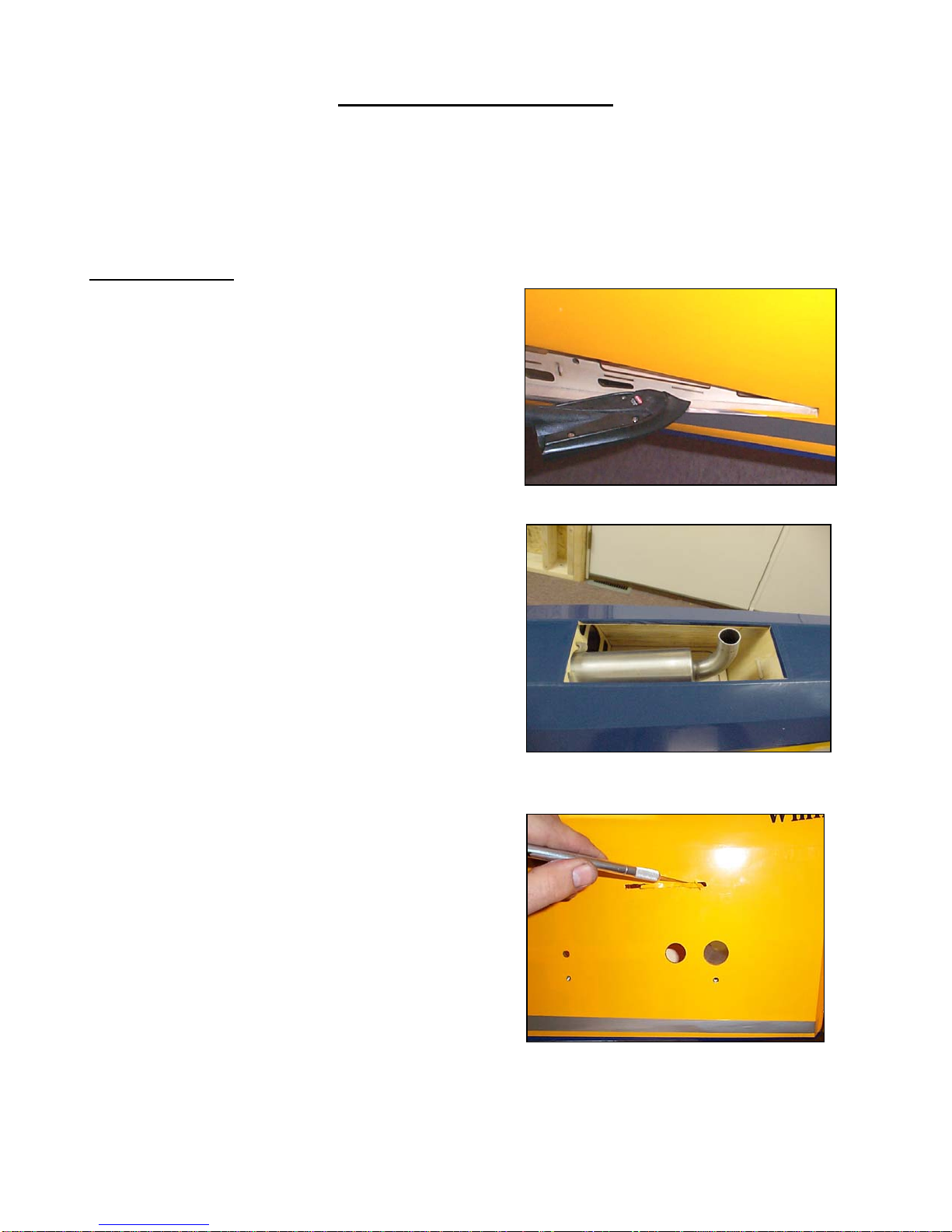
1. Remove Covering from Fuselage
where wing will be inserted. First
drawing a line about ½” inside the balsa
opening, matching the contour of the
airfoil.
2. Using a Xacto knife with a new #11
blade, cut away covering from both
sides of the Fuselage.
3. Using your Sealing Iron, fold the ½”
covering inward onto balsa wing
opening and seal down in small 1-2”
segments until completed. FIG 1
4. Complete this step if you plan to install
Tuned Pipes/Canisters into your model.
Following procedures from previous
step, simply mark and cut covering ½”
inside the exhaust outlet located on the
bottom of Fuselage. Fold covering
inward and seal to the inside edges of
exhaust opening, you may consider
gluing the edge of covering with a very
small amount of CA to prevent covering
from lifting, due to heat. FIG 2
5. In this step we will cut open the 4
Canopy bolt holes located in the
fuselage (2 per side), using a pointed
#11 blade. First you will need to seal
around each hole then open each hole,
removing covering, with a Xactro knife.
After you have removed the covering
from these holes, re-seal the edges
with your Sealing Iron to prevent
covering from lifting later.
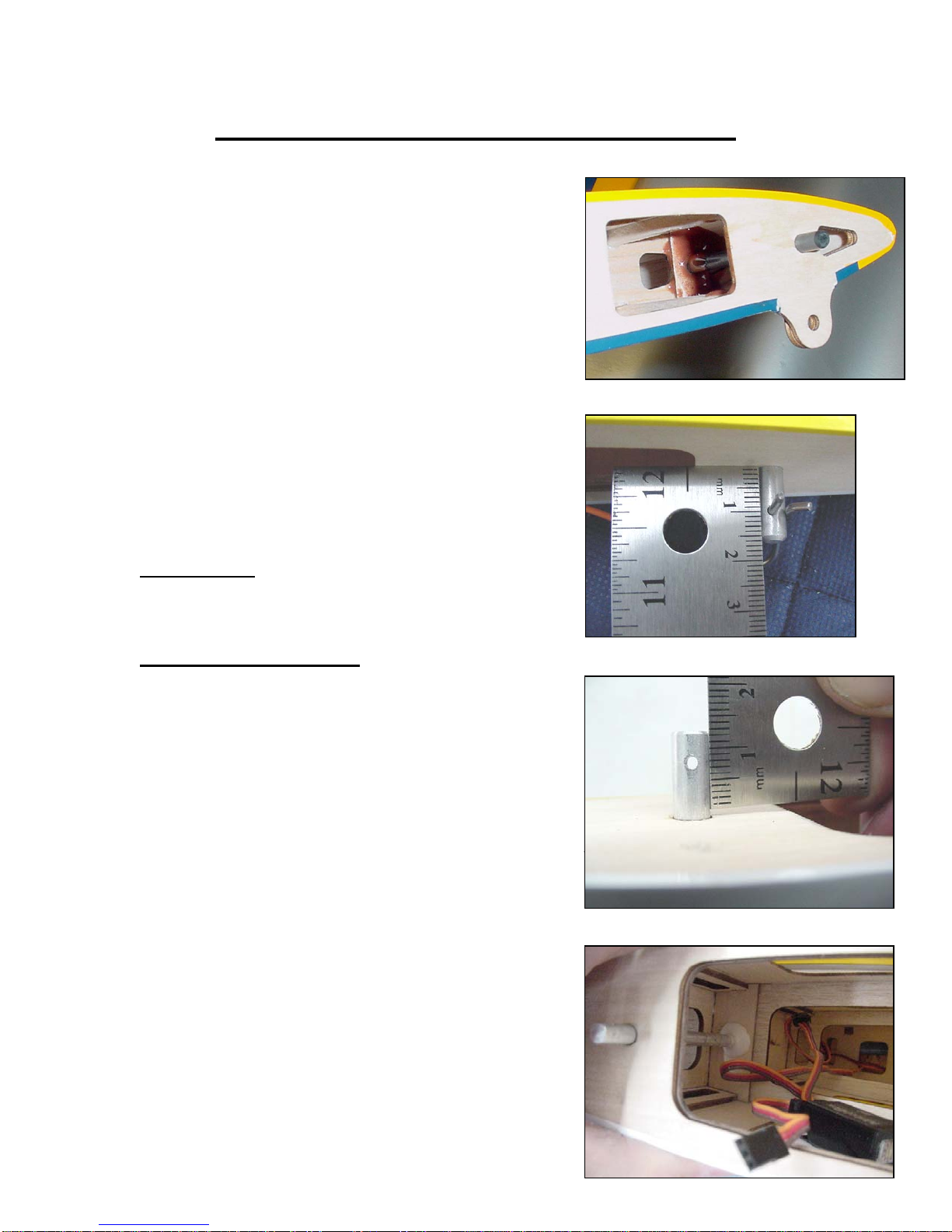
6. In FIG 3, you will need to remove
covering from the following areas on
each side of the Fuselage and seal the
edges with Sealing Iron.
•Rudder pull/pull slots
•Stabilizer tube holes
•Stabilizer bolt holes
•Stabilizer anti rotation pin holes
•Servo lead holes
FIG 1
FIG 3
FIG 2
9
Preparation and Installation of Hinges
Figure 2
Figure 1
Required Tools and Adhesive
•Xacto Knife, #11 Blade
•Sealing Iron
•Paper Towels
•Pacer Hinge Glue (PT-55)
Prepare Hinge Slots
Hinge Slots are installed in your model.
The Hinges have been placed into the slots
from the factory, they have not been glued
in place yet.
1. Start by removing all hinges from the
model and begin sealing the covering
at each hinge location. You will notice
that each hinge location has a slight
indent, seal covering down at all these
locations. FIG 1
2. Repeat these steps on all hinge slots
before proceeding on.
Number of Hinges:
•Wing- 9 ea.
•Stab- 4 ea.
•Rudder- 4
Install Hinges
The technique shown is very accurate and
is proven to be very strong. Follow along
closely as we install hinges into the
Stabilizer, then you can repeat these steps
as you install the remaining hinges into
your model using Pacer PT-55 Hinge Glue.
1. Hold bottle firmly against the Stabilizer
hinge slot and fill slot with glue. You
can use the tapered tip on your bottle,
this will help insert glue further into the
slot. Figure 2 Fill all four hinge slots in
Stabilizer and Elevator Half with glue.
Using damp paper towel, wipe any
excess glue protruding up from slots.
2. Center and slide hinges into Stabilizer
slots making sure they are seated
properly. ( the hinge pin should align to
the bevel) Next, slide Elevator onto
hinges, you will notice hinges may start
to mis-align from one another as they
settle into place. FIG 3 Use a small
pointed object and align hinges to pivot
point once elevator is in place . FIG 4
Again, hinge pin should align to the
bevel. Use masking tape to hold
elevator in place while glue dries.
3. Using these steps complete all
remaining hinges.
Figure 3
Figure 4
Wing and Stab Anti-Rotation Pin Installation
Required Tools FIG 1
•Epoxy and Thin CA
•Sand Paper
•Acetone or Alcohol
•Micro-balloons
1. Prepare the C/F anti-rotation pins by using coarse
sandpaper and rough up the end of the pin where it will be
inserted in the second rib in the H.Stab. Now clean the pins
with acetone or alcohol to remove any possible grease or dirt.
2. Use 5-10 minute epoxy to attach the pin to the number two
rib that is inside the horz stab. Then use thin C/A to attach the FIG 2
pin to the root rib of the horz stab.
3. Add a little extra fillet of epoxy with micro-balloons on the
inside rib around the anti-rotation pin to insure a strong bond
for the pins. FIG 1
4. If the anti-rotation pins fit too tightly in the fuse sides, it will
be necessary to open the holes in the fuse sides slightly with
a small rat tail file.
Very Important:
After completing the model and flying it, in case you noticed
any play in the stab, please glue the horizontal stab tube in
place in the fuselage with epoxy and micro-balloons.
Wing Rotation Pin Installation FIG 3
1. Prepare the aluminum anti-rotation pins by using coarse
sandpaper and rough up the end of the pin where it will be
inserted in the second rib in the wing. Now clean the pins
with acetone or alcohol to remove any possible grease or dirt.
2. Install the anti-rotation pins using the following dimensions.
The front pin should measure 10.5mm. Note: FIG 2 the picture
showing the measurement with the ruler may not look like
exactly 10.5 however 10.5 mm is the correct distance from
the root rib to the center hole for the keeper clip at the end
of the anti-rotation pin. Also this ruler starts at zero, yours
may not start at zero. The rear pin FIG 3 should measure 8 mm from
from the root rib to the center of the hole. The front and rear pin
should have the hole in a vertical position.
3. Apply 5-minute epoxy in the second wing rib holes.
Lay the wing flat on the table to insert the anti-rotation pins. FIG 4
Now insert the pins to the correct depth. Again, check the hole
in the end of the pins to make sure the front and rear pins are
vertical as this is very important
4. Let the epoxy harden. Stand the wing on its wing tip and
run some thin C/A around the root rib. Wipe away any excess.
Do this several times which will help to seal the pin to the hole
in the root rib.