HER CHEE ADLY RT-50 User manual

SERVICE MANUAL
RT-50
January 2008
High power Engine
HER CHEE INDUSTRLAL CO., LTD.

INTRODUCTION
This Service Manual is provided as the technical information
for the check & preparation of ADLY RT-50 scooter, and the
direction edited is given in diagrams with "Operation Sequence",
"Key Points", and "Adjustment of Check" for reference of the
service staffs.
This Service Manual is finished in accordance with the model
of RT-50. Taking new model as standard if there are differences
between the models described in this manual and the actual
scooter.
HER CHEE INDUSTRIAL CO., LTD.

CONTENTS
Chapter 01 Chapter 1 INFORMATION FOR PREPARATION………… 1
Chapter 02 CHECK AND ADJUST………………………………………….
Chapter 03 ENGINE REMOVAL…………………………………………….
Chapter 04 CYLINDER HEAD / CYLINDER / PISTON…………………..
Chapter 05 CRANK CASE & CRANK SHAFT…………………………….
Chapter 06 Transmission……………………………………………………
Chapter 07 Final Transmission Mechanism……………………………..
Chapter 08 Fuel System……………………………………………….........
Chapter 09 Front Wheel / Front Suspension / Front Brake……………
Chapter 10 Rear Wheel / Suspension / Brake……………………………
Chapter 11 Electrical Device………………………………………………..

Chapter1 InformationforPreparation
Attention on Operation
zAll washers, oil rings, clamp rings, opening pins shall be duly replaced by a new
item when dismounted.
zLocking of all screws, nuts, cross screws shall be performed in the order of first
the large screws and then the small ones and from inside to outside in opposite
angles by tightening the torque locks.
zAll items must use original parts, pure oil and greases.
zAll service shall use special tools and general tools to repair.
zAll dismounted items requiring for checks shall be duly cleaned and for assembly,
all items shall be duly lubricated.
Chapter1 InformationforPreparation
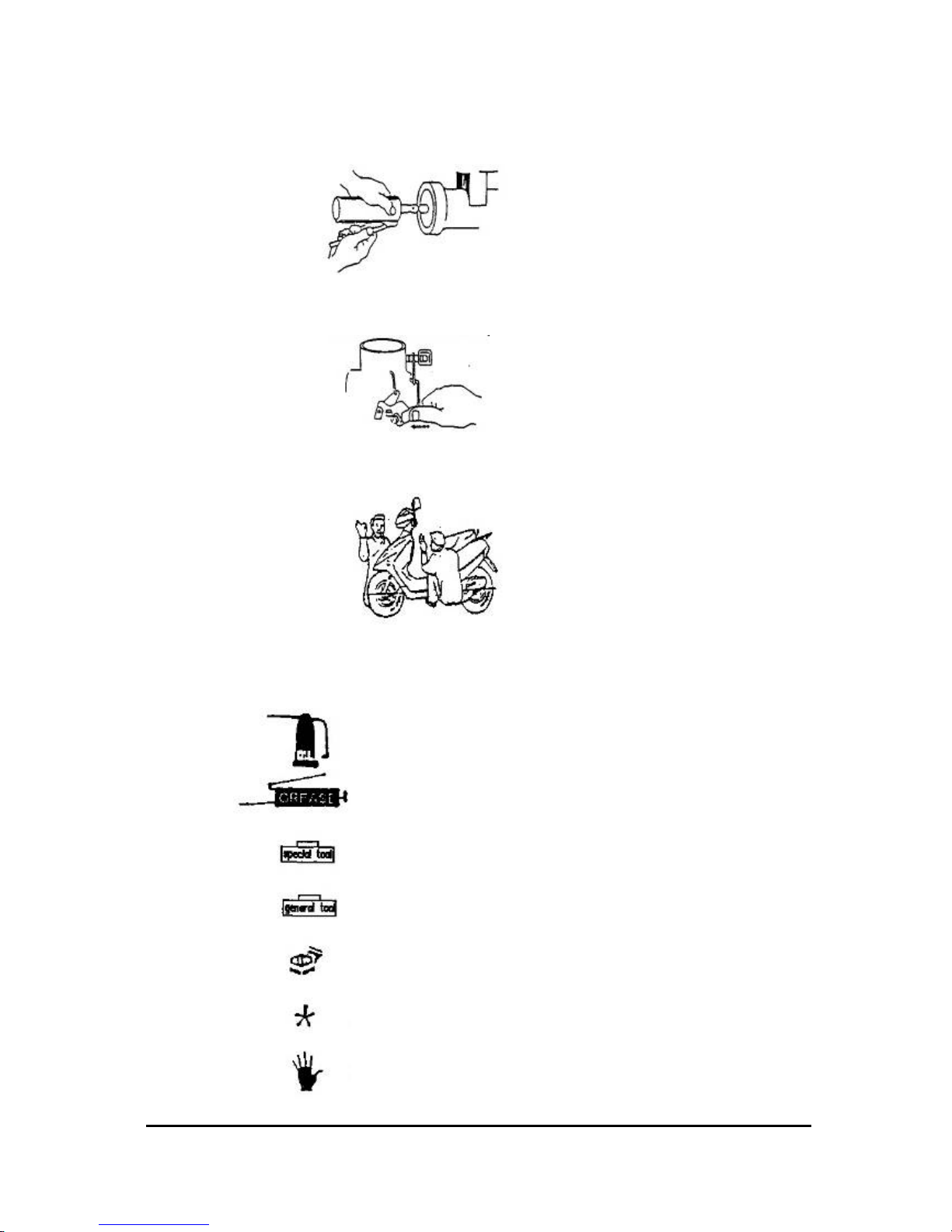
Attention on Operation
zCertified lubricants in cans shall be used on all the elements to be lubricated.
zAfter assembly, performance of all elements shall be duly checked and the
locking shall be duly verified.
zIn case of an operation is performed by over 2 people, the assignment shall be
conducted in coordination and safety shall be the first priority.
zDefinition of signs:
The sign given in the Service Manual shall refer to the operation methods and
observation.
OIL: Lubrication by designated lubricant.
GREASE: Lubrication by grease
Special Tool: Parts on which special tools shall be
used
General Tool: General tools shall be used
New: Replace by new items after dismounting
Attention
Dangerous and important operations
Chapter1 InformationforPreparation
Table of contents
Popular Motorcycle manuals by other brands

MV Agusta
MV Agusta Brutale 675 Workshop manual

APRILIA
APRILIA RSV MILLE - PART 1 1999 User manual content

Royal Enfield
Royal Enfield Himalayan 2018 owner's manual

SSR Motorsports
SSR Motorsports Lazer5 owner's manual

MOTO GUZZI
MOTO GUZZI 2005 Griso 1100 Use and maintenance book

KTM
KTM 85 SX 19/16 owner's manual


