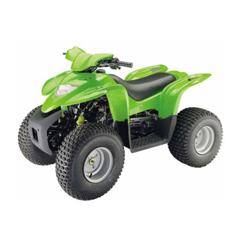
HER CHEE ATV-600 User manual

SERVICE MANUAL
ATV-600
Aug, 2011
HER CHEE INDUSTRIAL CO., LTD.

Foreword
This service manual contains information on servicing ATV-600
This manual is written for use as a guideline only. It is recommended that any
mechanic, with or without sufficient experience, thoroughly read through the manual
and only attempt to service those areas that are fully understood in accordance with
the guidelines provided by this manual. For fully qualified mechanics, this manual
supplies service data necessary for repairs and maintenance. It is highly
recommended that a qualified mechanic, regardless of technical level, should study
the service manual in full before attempting service on ATV-600
All the data and diagrams provided in this service manual are valid at the time of
publication. Information may be updated without notice due to improvements or
upgrades.
No quotation, reproduction, or reprint of the service manual, as a whole or in part,
will be permitted without the express written consent from ADLY Motor sports.

HOW TO USE THIS MANUAL
This service manual describes basic information of different system parts and
system inspection & service for ADLY ATV-600. In addition, please refer to
the manual contents in detailed for the model you serviced in inspection and
adjustment.
Chapter.1 includes general information and trouble diagnosis.
Chapter 2 includes service maintenance information and special tools manual.
Chapter 3~12 includes engine and driving systems.
Chapter 13 includes cooling system.
Chapter 14~17 includes assembly frame body.
Chapter 18 includes electrical equipment.
Chapter 19 includes wiring diagram.
Please see index of content for quick having the special parts and system
information.

CONTENTS Index
Chapter 1 GENERALINFORMATION 1
Chapter 2 MAINTENANCE INFORMATION 2
Chapter 3 LUBRICATIONSYSTEM 3
Chapter 4 FUELSYSTEM 4
Chapter 5 ENGINEREMOVAL 5
Chapter 6 CYLINDERHEAD/VALVE 6
Chapter 7 CYLINDER/PISTON 7
Chapter 8 V BELT DRIVING SYSTEM 8
Chapter 9 TRANSMISSION 9
Chapter 10 WHEEL, DRIVE SHAFT & PROPELLER SHAFT 10
Chapter 11 A.C GENERATOR/STARTING CLUTCH 11
Chapter 12 CRANKCASE / CRANKSHAFT 12
Chapter 13 COOLINGSYSTEM 13
Chapter 14 BODYCOVER 14
Chapter 15 FRONT BRAKE AND FORNT WHEEL 15
Chapter 16 STEERING/FRONT SUSPENSION 16
Chapter 17 REAR BRAKE / WHEEL / SUSPENSION 17
Chapter 18 ELECTRICAL EQUIPMENT 18
Chapter 19 ELECTRICALDIAGRAM 19

Ch. 1 GENERAL INFORMATION
Vehicle Identification Number
Frame Number:
*The frame serial number is
engraved on lower front right side of the
frame, which is under the front
differential box.
VIN Plate
** The VIN (Vehicle Identification
Number) is attached to the lower
front right side of frame behind the
radiator.
Engine Number
*The engine serial number is stamped
on the lower right side of the transmission
cover.
Engine No.

Ch. 1 GENERAL INFORMATION
1-1
Symbols and Marks ………………………1-1 Specifications …………………………..1-9
General Safety ……………………………...1-2 Locking Torque ………………………..1-10
Attention on operation ...………………….1-4 Troubles Diagnosis …………………...1-12
Symbols and Marks
Symbols and marks are used in this manual to indicate what and where the special service
is needed. In case supplemental information of procedures is needed for these symbols
and marks, explanations will be added to the text instead of using the symbols or marks.
Warning Means that serious injury or even death may result if procedures are
not followed.
Caution Means that equipment damages may result if procedures are not
followed.
Engine oil Limits to use SAE 10W-40 API SG class oil. Warranty will not cover
the damage that caused by not apply with the limited engine oil.
Grease Chassis grease is recommended.
Gear oil Gear oil serials are recommended. (Gear oil SAE 80/90 is
recommended )
Locking
sealant Apply sealant; medium strength sealant should be used unless
otherwise specified.
Oil seal Apply with lubricant.
Renew Replace with a new part before installation.
Brake fluid Use recommended brake fluid DOT4.
Special tools Special tools

Ch. 1 GENERAL INFORMATION
1-2
General Safety
Gasoline
Gasoline is a low ignition point and explosive material. Work in a well-ventilated
place, no flame or spark should be allowed in the work place or where gasoline is being
stored.
Caution
Gasoline is highly flammable, and may explode under some conditions, keep it
away from children.
Battery
Caution
-- Battery emits explosive gases; Flame is strictly prohibited. Keeps the place well
ventilated when charging the battery.
-- Battery contains sulfuric acid (electrolyte) which can cause serious burns so be
careful do not spray on your eyes or skin. If you get battery acid on your skin, flush it off
immediately with water. If you get battery acid in your eyes, flush it off immediately with
water and then go to hospital to see an ophthalmologist.
-- If you swallow it by mistake, drink a lot of water or milk, and take some laxative such
as castor oil or vegetable oil and then go to see a doctor.
-- Keep electrolyte beyond reach of children.
Carbon monoxide
If you must run your engine, ensure the place is well ventilated. Never run your
engine in a closed area.
Run your engine in an open area, if you have to run your engine in a closed area,
be sure to use an extractor.
Caution
Exhaust contains toxic gas which may cause one to lose consciousness and even
result in death.

Ch. 1 GENERAL INFORMATION
1-3
Used engine oil
Caution
Prolonged contact with used engine oil (or transmission oil) may cause skin cancer
although it might not be verified. We recommend that you wash your hands with soap
and water right after contacting.
Keep the used oil beyond reach of children.
Hot components
Caution
Components of the engine and exhaust system can become extremely hot after
engine running. They remain very hot even after the engine has been stopped for some
time. When performing service work on these parts, wear insulated gloves and wait
until cooling off.
Brake pad
Do not use an air hose or a dry brush to clean components of the brake system;
use a vacuum cleaner or the equivalent to avoid dust flying.
Caution
Inhaling brake shoe or pad ash may cause disorders and cancer of the breathing system.
Brake fluid
Caution
Spilling brake fluid on painted, plastic, or rubber parts may cause damage to the
parts. Place a clean towel on the above-mentioned parts for protection when servicing
the brake system. Keep the brake fluid beyond reach of children.

Ch. 1 GENERAL INFORMATION
1-4
Attention on Operation
All washers, oil rings, clamp rings, opening pins shall be duly replaced by a new item
when dismounted.
Locking of all screws, nuts, cross screws shall be performed in the order of first the large
screws and then the small ones and from inside to outside in opposite angles by
tightening the torque locks.
All items must use original parts, pure oil and greases.
All service shall use special tools and general tools to repair.
All dismounted items requiring for checks shall be duly cleaned and for assembly, all
items shall be duly lubricated.

Ch. 1 GENERAL INFORMATION
1-5
Attention on Operation
Certified lubricants in cans shall be used on all the elements to be lubricated.
After assembly, performance of all elements shall be duly checked and the locking shall
be duly verified.
In case of an operation is performed by over 2 people, the assignment shall be
conducted in coordination and safety shall be the first priority.
Remove residues of the old gasket or sealant before reinstallation, grind with a
grindstone if the contact surface has any damage.
The ends of rubber hoses (for fuel, vacuum, or coolant) should be pushed as far as they
can go to their connections so that there is enough room below the enlarged ends for
tightening the clamps.

Ch. 1 GENERAL INFORMATION
1-6
Rubber and plastic boots should be properly reinstalled to the original correct positions
as designed.
The tool should be pressed against two (inner and outer) bearing races when removing
a ball bearing. Damage may result if the tool is pressed against only one race (either
inner race or outer race). In this case, the bearing should be replaced. To avoid
damaging the bearing, use equal force on both races.
Before battery removal operation, it has to remove the battery negative (-) cable firstly.
Tools like open-end wrench do not contact with body to prevent from short-circuit and
create spark.
After service completed, make sure all connection points is secured. Battery positive (+)
cable should be connected firstly. And the two posts of battery have to be greased after
connected the cables.
If fuse burned, it has to find out the cause and solved it. And then replace with specified
capacity fuse.

Ch. 1 GENERAL INFORMATION
1-7
When separating a connector, it locker has to Insert the terminal completely, unlocked it
first. Then, conduct the service Check if the terminal is covered by the boot. Do not let
boot open facing up.
Make sure the connector pins are not bent, extruded or loosen.
Do not pull the wires as removing a connector or wires. Hold the connector body.
Insert the connector completely. If there are two lockers on two connector sides, make
sure the lockers are locked in properly. Check if any wire loose.
Check if the connector is covered by both connector boots completely and secured
properly.

Ch. 1 GENERAL INFORMATION
1-8
Definition of signs:
The sign given in the Service Manual shall refer to the operation methods and
observation.
OIL: Lubrication by designated lubricant.
GREASE: Lubrication by grease
Special Tool: Parts on which special tools shall be used
General Tool: General tools shall be used
New: Replace by new items after dismounting
Attention
Caution: Beware of the operation and process.

Ch. 1 GENERAL INFORMATION
1-9
Specifications
MODEL ATV-600
OVERALL
LENGTH 2150 mm GEARS L / H / N / R / P
OVERALL
WIDTH 1280 mm FRONT DRIVE 4x4 with Differential Lock
OVERALL
HEIGHT 1250 mm REAR DRIVE Shaft drive
WHEEL BASE 1320 mm OIL CAPACITY
3.0L
(Without oil filter change :
2.4L)
(With oil filter change:
2.7L)
NET WEIGHT 332 kg FRONT DIFF.
GEAR OIL 150cc
(SAE 80 or SAE 90)
DISPLACEMENT 565 cc REAR GEAR OIL 250cc
(SAE 80 or SAE 90)
TYPE 4-stroke, 4V electroplated
ceramic cylinder
HEAD LIGHT
BULB (HIGH /
LOW)
H3 12V 55W x 2
H7 12V 55W x 2
FUEL
TANK CAPACITY Unleaded (octane 90 or
higher) / 18 Liter FRONT POS.
LIGHT LED 12V 0.5W x 2
COMPRESSION
RATIO 10.2:1 BRAKE LIGHT
BULB(TAIL LIGHT) 12V 5W / 21W x 2
STARTING Electric & Recoil Starter TURN SIGNAL
LIGHT BULB 12V 10W x 4
TRANSMISSION CVT FRONT
SUSPENSION Double A-Arm
SPARK PLUG NGK, CR8E REAR
SUSPENSION Independent Rear
Suspension
PERFORMANCE 15KW / 30KW (OPEN) FRONT TIRE 25x8-12, (Opt. 26x8-14)
BATTERY 12 volts, 12 Ah REAR TIRE 25x10-12, (Opt. 26x10-14)
COOLING TYPE Water-cooled TIRE PRESSURE
Front: 5.0 psi
Rear: 5.0 psi
(the tire pressure would
depends on the
application and type)
AIR CLEANER Sponge, Wet type
※ Manufacturer reserves the right to make change without notice.

Ch. 1 GENERAL INFORMATION
1-10
Locking Torque
The standard locking torque shall apply in case of no specification.
Standard Torque:
Type Torque (kg-m) Type Torque (kg-m)
5 mm bolt, nut 0.45~0.6 5 mm screw 0.35~0.5
6 mm bolt, nut 0.8~1.2 6 mm screw, SH nut 0.7~ 1.1
8 mm bolt, nut 1.8~2.5 6 mm flange bolt, nut 1.0 ~1.4
10 mm bolt, nut 3.0~4.0 8 mm flange bolt, nut 2.4 ~3.0
12 mm bolt, nut 5.0~6.0 10 mm flange bolt, nut 3.5~4.5
Engine Torque Value:
Locking Position Qt’y Dia. (mm) Torque (kg-m) Remark
Cylinder stud bolt 4 10 1.0~1.4
Cylinder head nut 4 8 3.6~4.0
Cylinder head right bolt 2 8 2.0~2.4
Cylinder head side cover bolt 2 6 1.0~1.4
Cylinder head cover bolt 4 6 1.0~1.4
Cylinder head stud bolt (IN. pipe) 2 6 1.0~1.4
Cylinder head stud bolt (EX. pipe) 2 8 2.4~3.0
Air inject pipe bolt 4 6 1.0~1.4
Tapper adjustment screw nut 4 5 0.7~1.1
Spark plug 1 10 1.0~1.2
Tensioner lifter bolt 2 6 1.0~1.4
Carburetor insulator bolt 2 6 0.7~1.1
Oil pump screw 2 3 0.1~0.3
Water pump impeller 1 7 1.0~1.4
Engine left cover bolt 9 6 1.1~1.5
Engine oil draining bolt 1 12 3.5~4.5
Engine oil strainer cap 1 30 1.3~1.7
Mission draining bolt 1 8 1.1~1.5
Mission filling bolt 1 12 3.5~4.5
Shift drum fixing bolt 1 14 3.5~4.5
Clutch driving plate nut 1 28 5.0~6.0
Clutch outer nut 1 14 5. 0~6.0
Drive face nut 1 14 8.5~10.5
ACG. Flywheel nut 1 14 5.0~6.0
Crankcase bolts 7 6 0.8~1.2
Mission case bolt 7 8 2.6~3.0
Apply oil to thread

Ch. 1 GENERAL INFORMATION
1-11
Chassis:
Locking Position Qty Dia. (mm) Torque (kg-m) Remark
Handlebar upper holder bolt 4 6 2.3
Steering shaft bottom nut 1 14 5.5
Ball joint fixed nut 4 10 4.0
Steering shaft holder bolt 2 8 2.3
Front axle lock nut 2 20 10
Rear axle lock nut 2 20 10
Engine hanger nut 3 10 4.0
Drive gear bolt 5 10 5.5
Driven gear nut 4 10 5.5
Front / Rear suspension arm bolt 8 10 4.5
Front / Rear suspension arm nut 8 10 4.5
Brake lever bolt 2 5 1.0
Brake hose bolt 13 10 2.3
Brake caliper bolt 6 8 4.0
Foot rest flange bolt 6 8 4.0
Exhaust muffler mounting bolt 2 8 2.9
Exhaust muffler connection nut 2 8 2.5
Engine mounting flange nut 2 8 2.5
Engine mounting bracket bolt 5 10 4.0
Wheel nut, front and rear 16 10 5.0

Ch. 1 GENERAL INFORMATION
1-12

Ch. 1 GENERAL INFORMATION
1-13

Ch. 1 GENERAL INFORMATION
1-14

Ch. 1 GENERAL INFORMATION
1-15
Table of contents
Other HER CHEE Offroad Vehicle manuals


