HER CHEE ATV-320 U User manual

SERVICE MANUAL
ATV-320 S/U
2002/24
JUNE 30, 2007
High Power Liquid Cooled Engine
HER CHEE INDUSTRIAL CO., LTD.

F-2
Foreword
This service manual contains information on servicing ATV-320(S/U)
This manual is written for use as a guideline only. It is recommended that any
mechanic, with or without sufficient experience, thoroughly read through the manual
and only attempt to service those areas that are fully understood in accordance with
the guidelines provided by this manual. For fully qualified mechanics, this manual
supplies service data necessary for repairs and maintenance. It is highly
recommended that a qualified mechanic, regardless of technical level, should study
the service manual in full before attempting service on ATV-320
All the data and diagrams provided in this service manual are valid at the time of
publication. Information may be updated without notice due to improvements or
upgrades.
No quotation, reproduction, or reprint of the service manual, as a whole or in part, will
be permitted without the express written consent from ADLY Motor sports.

F-3
CONTENTS
General Information & Lubrication
General Information --------------------------------------- F-4
Information for Preparation ------------------------------ F-5
Lubrication --------------------------------------------------- F-7
Chapter 1 Engine, Transmission & Gear
Engine Removal & Installation ------------------------- I-2
Cylinder Head & Valve ----------------------------------- I-5
Cylinder & Piston ------------------------------------------ I-20
Crankcase & Crankshaft --------------------------------- I-27
Cooling System -------------------------------------------- I-33
Transmission & Gear ------------------------------------- I-38
Chapter 2 Fuel System & Carburetion
Carburetor -------------------------------------------------- II-3
Fuel Tank ---------------------------------------------------- II-7
Air Cleaner -------------------------------------------------- II-10
Exhaust System -------------------------------------------- II-12
Chapter 3 Ignition and Starting System
Ignition System ---------------------------------------------- III-1
Starting System --------------------------------------------- III-4
Recoil Backup Starting System ------------------------- III-7
Chapter 4 Frame & Cover
Frame & Cover --------------------------------------------- IV-2
Chapter 5 Wheel, Tyres & Brakes -----------------------------------
Handlebar & Steering ------------------------------------- V-2
Front & Rear Wheel --------------------------------------- V-6
Suspension System --------------------------------------- V-9
Hydraulic Brake -------------------------------------------- V-14
Chapter 6 Electrical Equipment
Alternator & Starter Gear--------------------------------- VI-2
Electrical Equipment ------------------------------------- VI-10
Wire Diagram ---------------------------------------------- VI-13
F-4
General Information
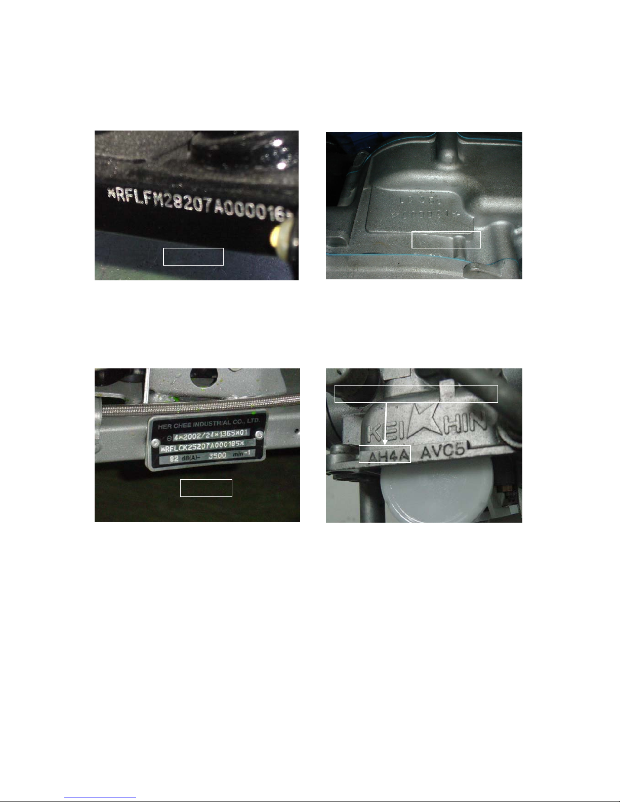
MODEL IDENTIFICATION
The frame serial number is stamped on the
lower front right side of frame.
The VIN (Vehicle Identification Number) is
attached to the lower front right side of frame
behind the frame number.
The engine serial number is stamped on the
upper rear right crankcase.
The carburetor identification number is
stamped on the right side of the carburetor.
VIN No.
Frame No. Engine No.
Carburetor Identification No.

F-5
Information for Preparation
ATTENTION ON OPERATION
zAll washers, oil rings, clamp rings, opening pins shall be duly replaced by a new item when
dismounted.
zLocking of all screws, nuts, cross screws shall be performed in the order of first the large screws
and then the small ones and from inside to outside in opposite angles by tightening the torque
locks.
zAll items must use original parts, pure oil and greases.
zAll service shall use special tools and general tools to repair.
zAll dismounted items requiring for checks shall be duly cleaned and for assembly, all items shall be
duly lubricated.
F-6
Information for Preparation
ATTENTION ON OPERATION
zCertified lubricants in cans shall be used on all the elements to be lubricated.
zAfter assembly, performance of all elements shall be duly checked and the locking shall be duly
verified.
zIn case of an operation is performed by over 2 people, the assignment shall be conducted in
coordination and safety shall be the first priority.
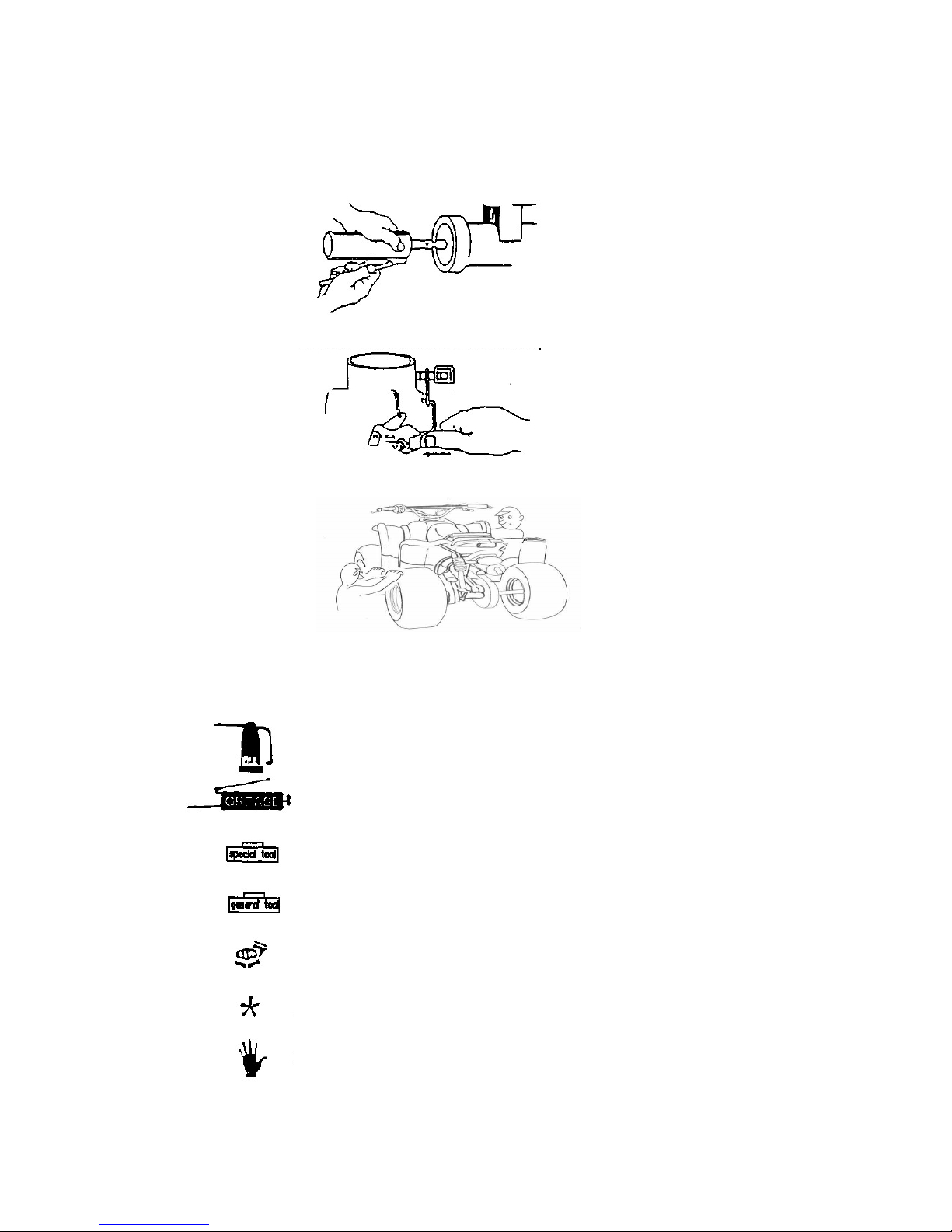
zDefinition of signs:
The sign given in the Service Manual shall refer to the operation methods and observation.
OIL: Lubrication by designated lubricant.
GREASE: Lubrication by grease
Special Tool: Parts on which special tools shall be used
General Tool: General tools shall be used
New: Replace by new items after dismounting
Attention
Dangerous and important operations

F-7
Lubrication
GENERAL
The maintenance of the oil pump and engine oil can be done with the engine install in the frame.
When removing and install the oil pump, use care not to allow dust or dirt to enter the engine and oil
line.
SPECIFICATION
ITEM STANDARD mm (in) SERVICE LIMT mm (in)
Rotor tip clearance 0.15 (0.006) 0.20 (0.008)
Body clearance 0.15-0.20 (0.006-0.008) 0.25 (0.010)
Oil pump
Rotor end clearance 0.04-0.09 (0.002-0.004) 0.12 (0.005)
TORQUE VALUES
Oil drain plug 20-25 N.m (15-18 ft-lb)
Oil filter screen cap 18-22 N.m (13-16 ft-lb)
Transmission oil check bolt 10-15 N.m (7-11 ft-lb)
Transmission oil drain bolt 10-15 N.m (7-11 ft-lb)
Troubleshooting
Oil level too low
◦External oil leaks
◦Worn valve guide or seal
◦Worn piston rings
Oil contamination
◦Oil not changed often enough
◦Head gasket faulty
◦worn piston rings
Low oil pressure
◦Oil level too low
◦Clogged oil filter, oil passage, and or oil pipe
◦Faulty oil pump

F-8
Engine Oil
OIL LEVEL
Warm up the engine.
Stop the engine and park the vehicle on level
ground.
Check the oil level through the oil window.
If the level is near the lower of the window, fill to
the middle level with the recommended engine oil.
OIL CHANGE
NOTE
◦Drain the oil from the crankcase while the engine
is warm.
This ensures complete and rapid draining.
Place the oil pan under the engine.
Remove the oil filler cap and oil drain plug and
drain the engine oil.
Remove the oil filter screen cap, spring and filter
screen, and clean the filter screen.
After the oil has been completely drained, be sure
the O-ring on the filter screen cap is in good
condition and install the filter screen with the
closed end facing out.
Install the spring and cap.
Torque: 18-22 N.m (13-16ft-lb)
Make sure that the sealing washer is in good
condition, install the drain plug and tighten it.
Torque: 20-25 N.m (15-18 ft-lb)
Fill the engine with recommended engine oil
through the oil filler hole.
ENGINE OIL CAPACITY:
0.8 Liter (0.85 US qt.) at change
Reinstall the oil filler cap and start the engine and
let it idle for a few minutes.
Recheck the oil level.
Check that there are no oil leaks.
Min. Level
Filter Screen
Oil Filler Cap
F-9
Oil Pump
OIL PUMP REMOVAL
Remove the right crankcase cover.
Remove the flywheel and starter idle and driven
gears.
Remove the attaching bolt and oil separator cover.
Remove the circlip, then remove the oil pump
drive chain and driven sprocket.
Remove the two oil pump mounting bolts and
remove the oil separator and oil pump.
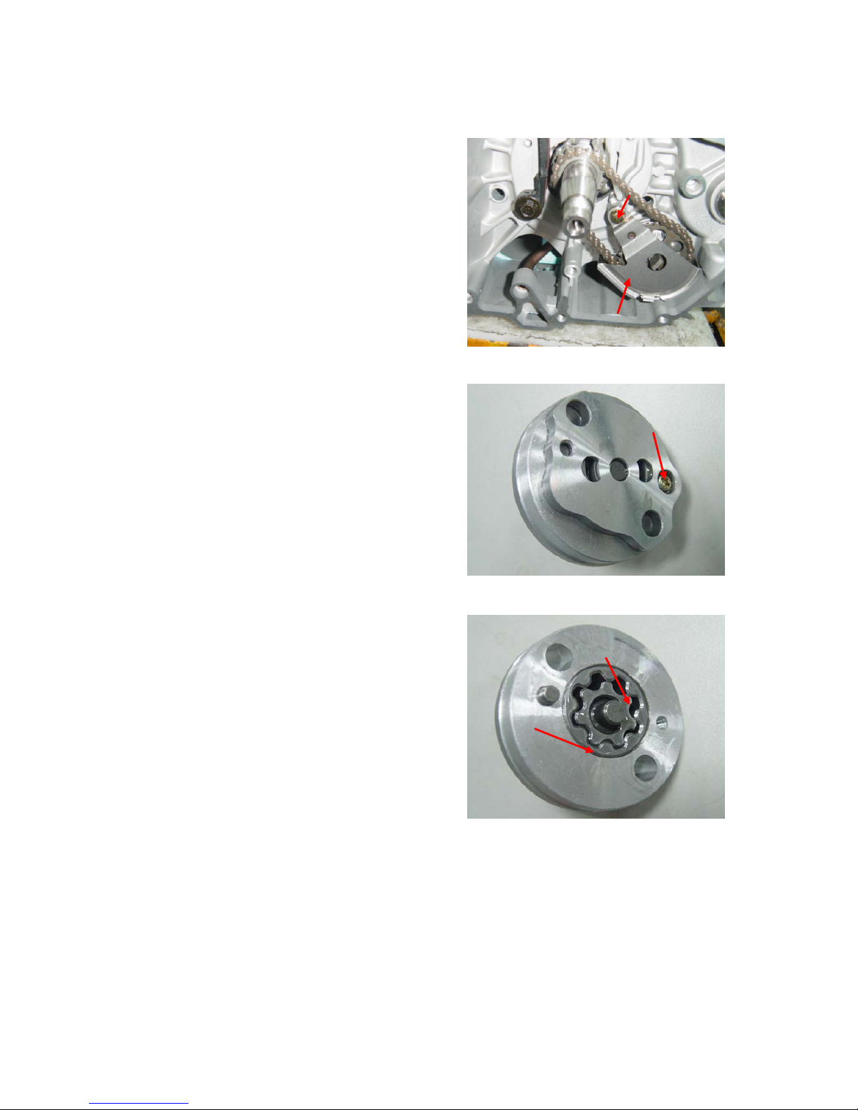
OIL PUMP DISASSEMBLY
Unscrew the pump cover attaching screw and
disassemble the oil pump.
OIL PUMP INSPECTION
Measure the pump body-to-outer rotor clearance.
Service Limit: 0.25 mm (0.010 in)
Measure the outer rotor-to inner rotor tip
clearance.
Service Limit: 0.20 mm (0.008 in)
Check the rotor-to pump body clearance.
Service Limit: 0.12 mm (0.005 in)
OIL PUMP ASSEMBLY
Install the outer and inner rotor into the pump
body.
Insert the pump shaft by aligning the flats of the
shaft and inner rotor.
Install the dowel pin.
Install the pump cover by aligning the hole of the
cover with the dowel pin.
Tighten the screw.
Make sure that the pump shaft rotates freely
without binding.
Bolt
Oil Separator Cover
Attaching Screw
Max. 0.25mm
Max. 0.20mm

Chapter 1 Engine, Transmission & Gear
I-1
Contents
Engine Removal & Installation
Cylinder Head & Valve
Cylinder & Piston
Crankcase&Crankshaft
Cooling System
Transmission&Gear
GENERAL SAFETY
WARNING
If the engine must be running to do some work, make sure the area is well-ventilated. Never run
the engine in a closed area. The exhaust contains carbon monoxide gas that may cause loss of
consciousness and lead to death.
WARNING
Gasoline is extremely flammable and is explosive under certain condition. Do not smoke or allow
flames or sparks in your working area.
WARNING
The battery electrolyte contains sulfuric acid. Protect your eyes, skin and clothing. In case of
contact, flush thoroughly with water and call a doctor if electrolyte gets in your eyes.
WARNING
The battery generates hydrogen gas which can be highly explosive. Do not smoke or allow flames
or sparks near the battery, especially while charging it.
SERVICE RULES
1. Use genuine ADLY or ADLY-recommended parts and lubricants or the equivalents. Parts that
do not meet ADLYs’ design specifications may damage the vehicle.
2. Use the special tools designed for this product.
3. Use only metric tools when service the vehicle. Metric bolts, nuts and screws are not
interchangeable with English fasteners. The use of incorrect tools and fasteners may
damage the vehicle.
4. Install new gaskets, O-ring, cotter pin, lock plates, etc. when reassembling.
5. When tightening a series of bolts or nuts, begin with large-diameter or inner bolts first and
tighten to the specified torque diagonally, unless a particular sequence is specified.
6. Clean parts in clean solvent upon disassembly. Lubricate any sliding surfaces before
reassembly.
7. After reassembly, check all parts for proper installation and operation.

Chapter 1 Engine, Transmission & Gear
I-2
Engine Removal/Installation
GENERAL
A floor jack or other adjustable support is required to support and maneuver the engine.
SPECIFICATION
Engine dry weight 32 kg (72 lb)
Oil capacity Engine 1.0 liter (1.06 US qt.) at disassembly
0.8 liter (0.85 US qt.) at change
Transmission 0.6 liter (0.74 US qt.) at disassembly
0.5 liter (0.63 US qt.) at change
Coolant capacity Engine and radiator 1.1 liter (1.16 US qt.)
Reserve tank 0.3 liter (0.31 US qt.)
Total 1.4 liter (1.47 US qt.)
TORQUE VALUES
Engine upper hanger plate 18 – 24 N.m (13 – 16 ft.lb)
Engine mounting nut 40 – 55 N.m (29 – 40 ft.lb)
Step bar rear bolt 40 – 55 N.m (29 – 40 ft.lb)
Step bar front bolt 18 – 24 N.m (13 – 16 ft.lb)
Chain cover bolt 10 – 14 N.m (7 – 10 ft.lb)
Chapter 1 Engine, Transmission & Gear
I-3
Engine Removal & Installation
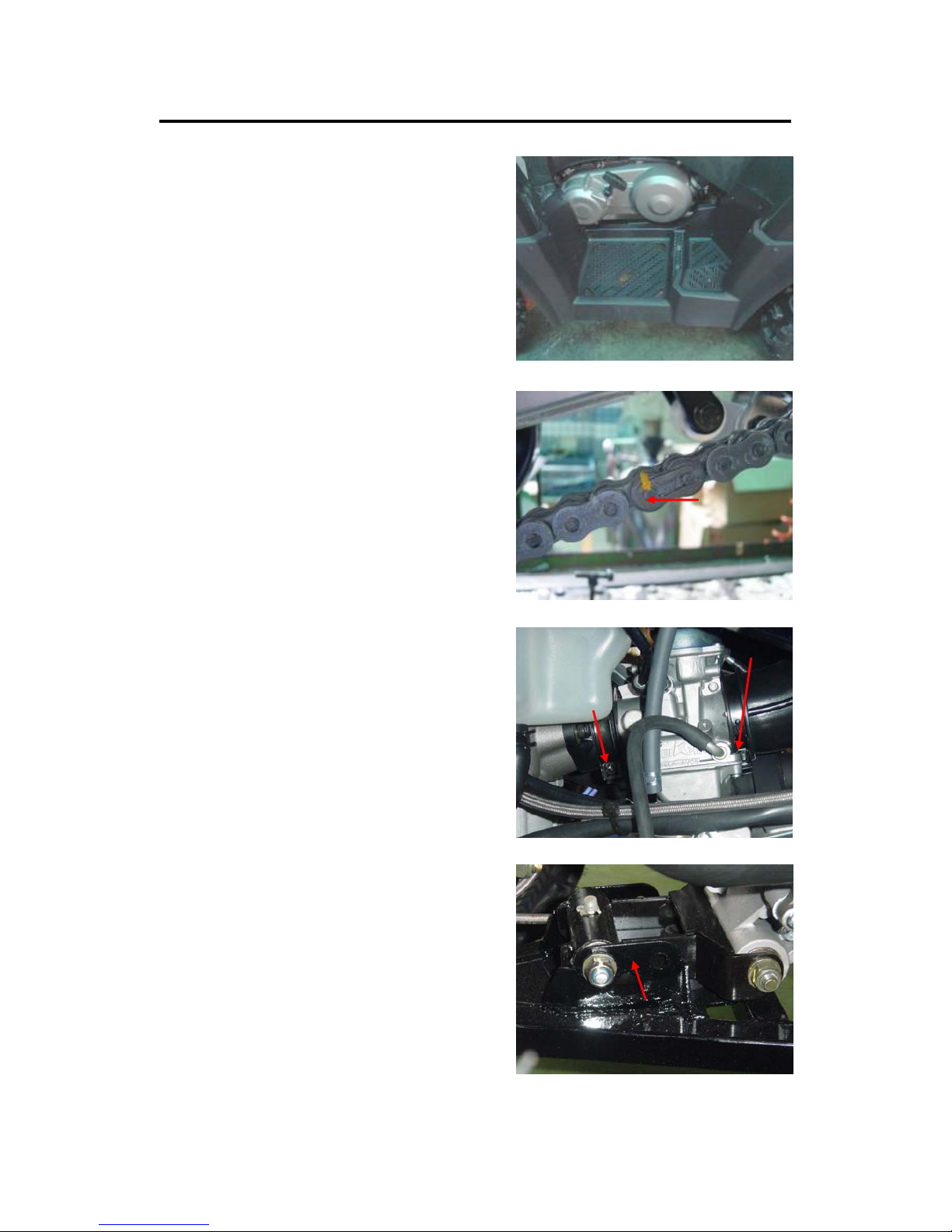
ENGINE REMOVAL
Park the vehicle on the level ground and
pull parking lever to park the vehicle.
Disconnect the battery ground (-) cable.
Remove left and right floor panel and step bar.
Remove foot brake pedal.
Remove front chain cover then disconnect drive
chain.
Disconnect gear selection rod then remove
muffler ass’y.
Disconnect coolant hose.
Disconnect spark plug and generator wire
connector and coupler
Disconnect blow-by tube at cylinder head cover
and crankcase.
Disconnect carburetor on intake manifold and
vacuum tube.
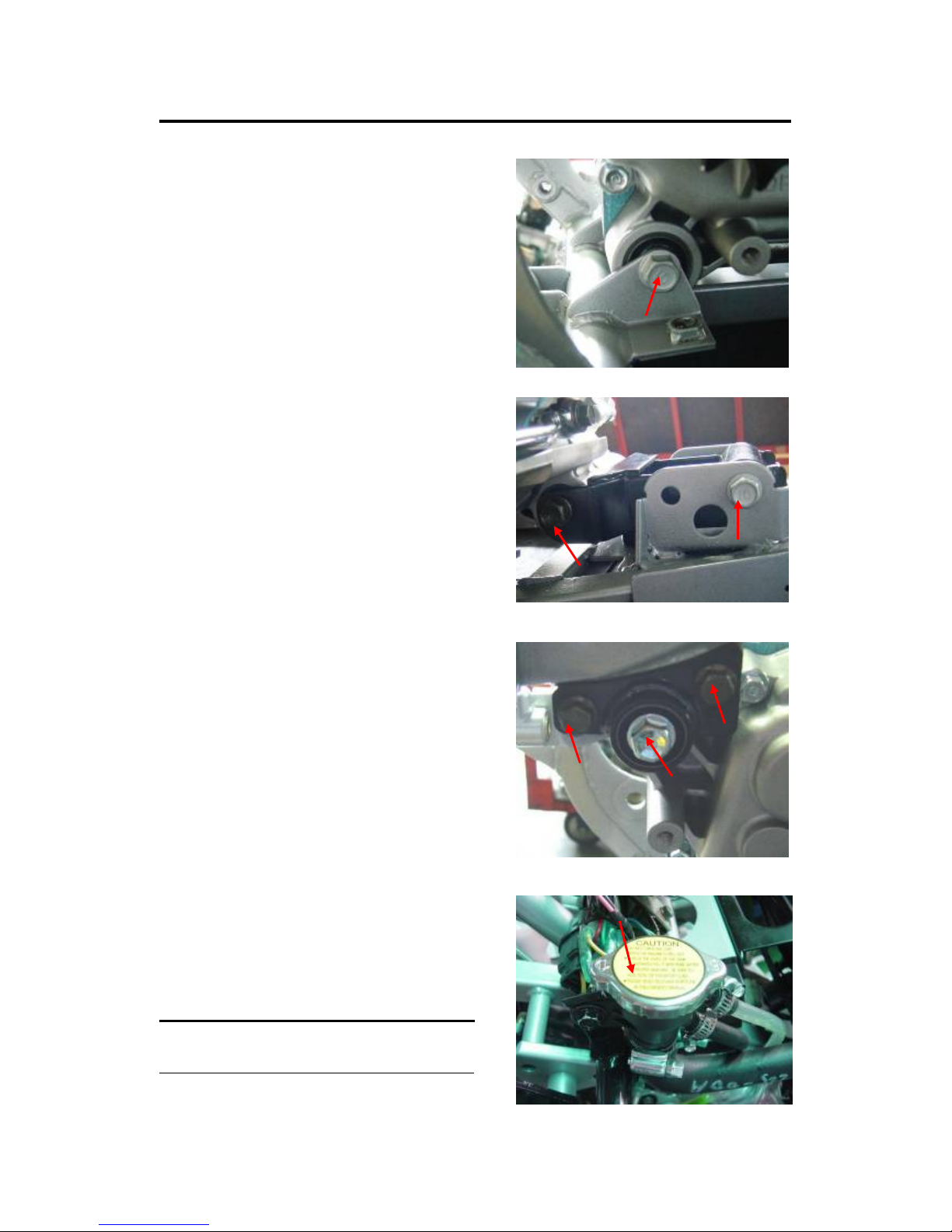
The engine is held in the frame by three point,
two at bottom an on at rear upper.
Loosen the all nuts on fixing studs and move all
studs.
Remove the front engine bracket.
Slightly raise the engine and pull it toward front
frame then pull out the engine thru right side.
Front engine bracket
Chapter 1 Engine, Transmission & Gear
I-4
ENGINE INSTALLATION
Move the engine into the frame
Insert the front engine bracket to correct position
then insert the bolts.
Insert all other engine mounting bolts and tighten
the nuts by following steps.
A. Rear lower engine mount
Torque value: 40 – 55 N.m (29 – 40 ft.lb)
B. Front engine mount
C. Front engine bracket
Torque value: 40 – 55 N.m (29 – 40 ft.lb)
D. Rear upper hanger plate
Torque value: 18 – 24 N.m (13 – 16 ft.lb)
E. Rear engine mount.
Torque value: 40 – 55 N.m (29 – 40 ft.lb)
Install the removed parts in the reverse order of
removal.
Refill coolant to specified volume and connect
battery terminals.
NOTE
◦Checked all connect points and oil level before
restarttheengine.
D
D
E
A
B
C

Chapter 1 Engine, Transmission & Gear
I-5
Cylinder Head Cover
1
5
2
3
7
6
4
8
11
10 95
5
5
9
Chapter 1 Engine, Transmission & Gear
I-6
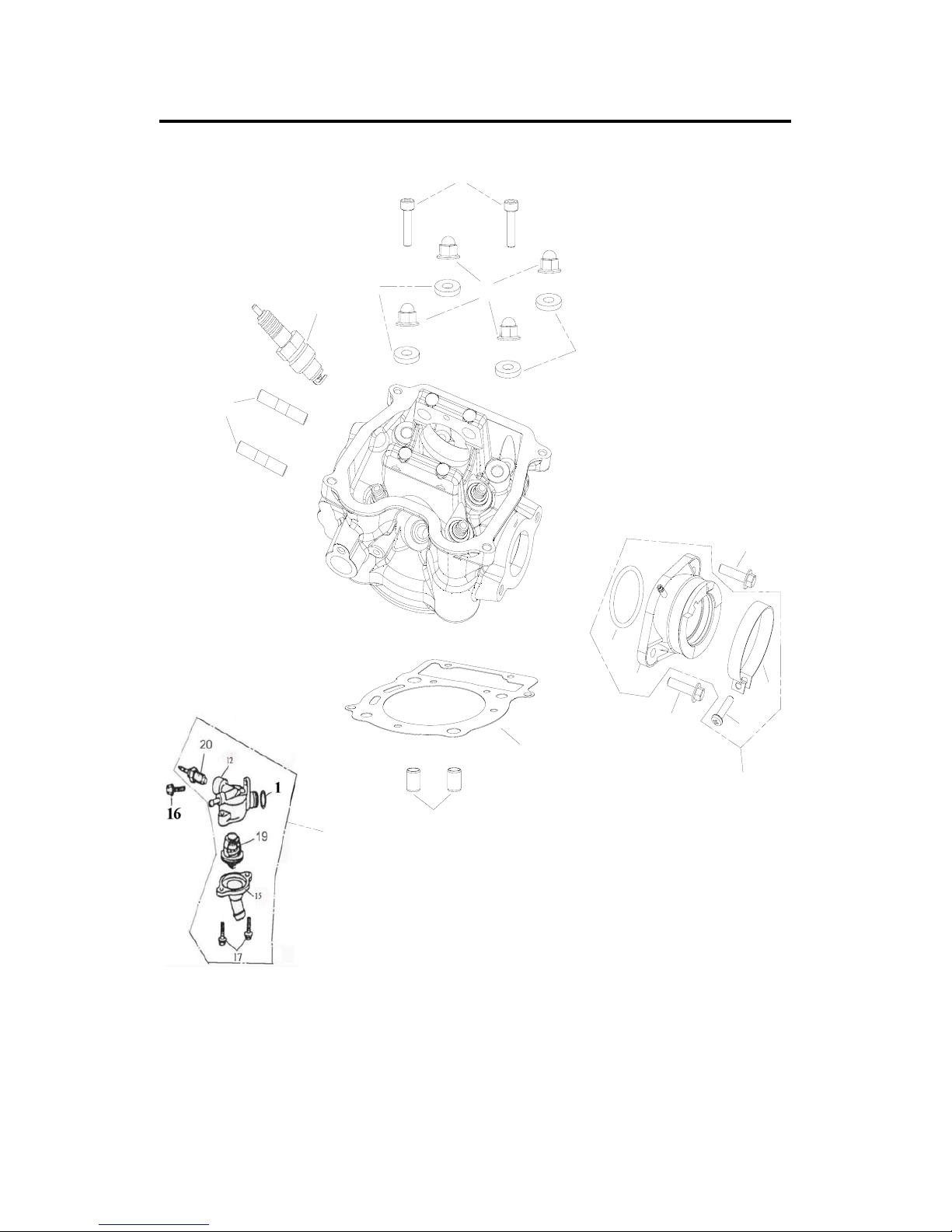
Cylinder Head
2
3
4
4
5
6
7
8
9
11
10
12
12
13
14
18
Chapter 1 Engine, Transmission & Gear
I-7
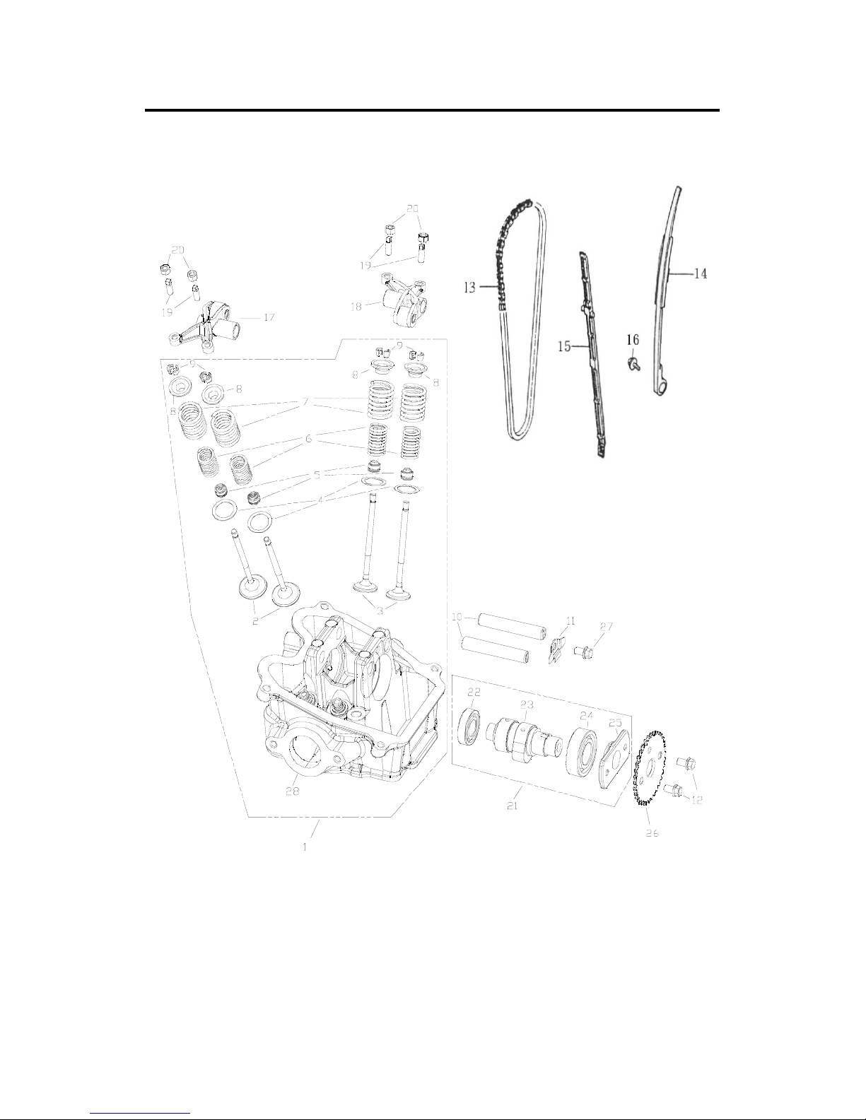
Camshaft / Valve / Cam
Chapter 1 Engine, Transmission & Gear
I-8
Cylinder Head/Valves Service Information
GENERAL
This section covers maintenance of the cylinder head, valves, camshaft and rocker arms.
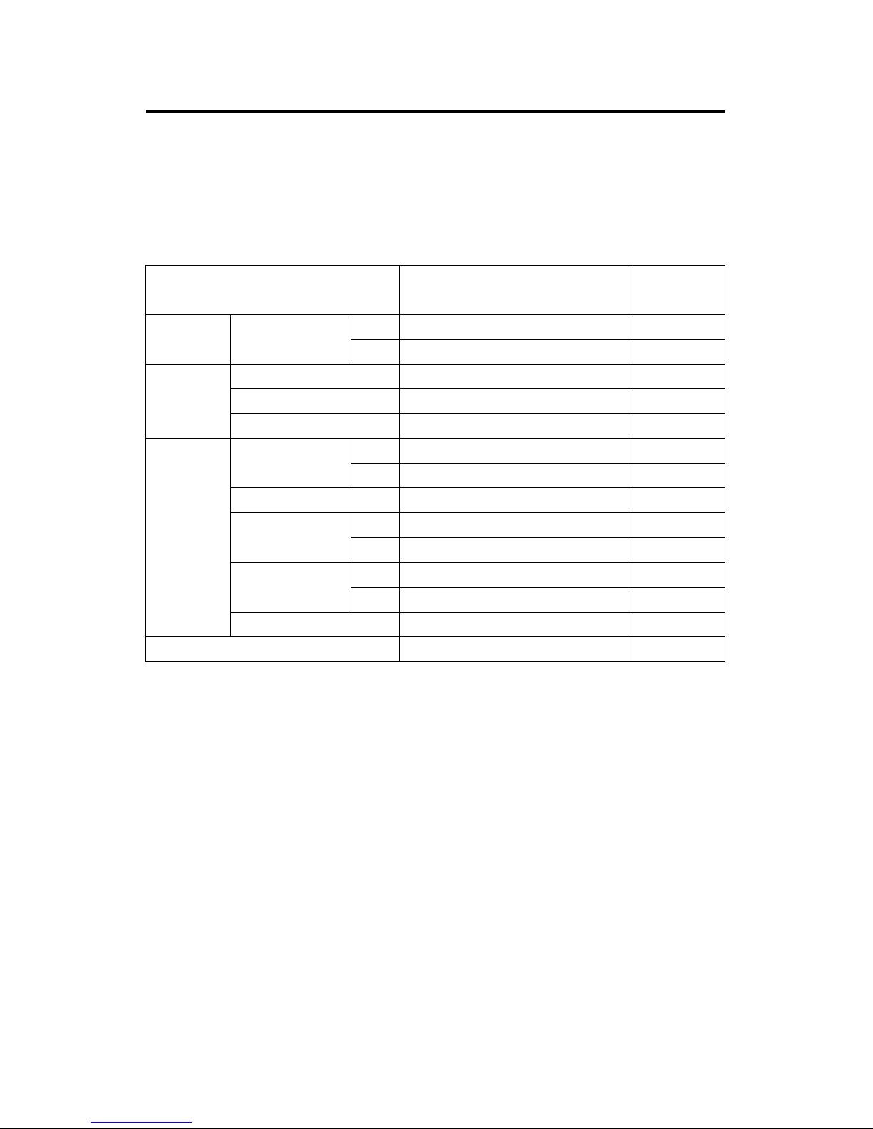
SPECIFICATION
Item Standard mm (in) Service Limit
mm (in)
IN 34.590-34.34.700 (1.3618-1.3661) 34.54 (1.3598)
Camshaft Cam height
EX 34.460-34.680 (1.3567-1.3654) 34.41(1.3547)
Rocker arm I.D. 11.000-11.018 (0.4330-0.4337) 11.10 (0.4370)
Shaft O.D. 10.966-10.984 (0.4318-0.4324) 10.91 (0.4295)
Rocker arm
Roller O.D. 17.00 (0.6693) 16.95 (0.6673)
IN 4.975-4.970 (0.1959-0.1965) 4.90 (0.193)
Valve stem
EX 4.955-4.970 (0.1951-0.1957) 4.90 (0.193)
Valve guide I.D. 5.00-5.012 (0.1969-0.1973) 5.03 (0.198)
IN 0.010-0.037 (0.0004-0.0015) 0.08 (0.003)Stem-to-guide
clearance EX 0.030-0.057 (0.0012-0.0022) 0.10 (0.004)
Inner 28.7 (1.13) 27.5 (1.08)Valve spring free
length Outer 32.0 (1.26) 30.4 (1.20)
Valve
Valve seat width 1.1 (0.04) 1.8 (0.07)
Cylinder head warpage - 0.05 (0.002)
TORQUE VALUES
Cylinder head cover screw 3.5-5.0 N.m (2.5-3.6ft.lb) Apply a locking agent
Cylinder cover bolt 8-12 N.m (6-9 ft.lb)
Cylinder head cap nut 22-28 N.m (16-19 ft.lb)
Camshaft holder bolt 8-12 N.m (6-9 ft.lb)
Cam chain tensioner sealing bolt 8-12 N.m (6-9 ft.lb)
Oil pipe bolt: 8 mm 8-12 N.m (6-9 ft.lb)
Exhaust pipe stud bolt 7-11 N.m (5-8 ft.lb)
Spark plug 15-20 N.m (11-15 ft.lb)

Chapter 1 Engine, Transmission & Gear
I-9
Troubleshooting
Engine top problems usually affect engine performance. These can be diagnosed by a
compression test, or by tracing noises with a sounding rod or stethoscope.
Low Compression
◦Valves
—Incorrect valve adjustment
—Burned or bent valves
—Incorrect valve timing
—Broken valve spring
◦Cylinder head
— Leaking or damaged head gasket
—Warped or cracked cylinder head
◦Cylinder and piston
Compression Too High
◦Excessive carbon build-up on piston or combustion chamber
Excessive Noise
◦Incorrect valve adjustment
◦Sticking valve or broken valve spring
◦Damaged or worn camshaft
◦Loose or worn cam chain
◦Worn or damaged cam chain tensioner
◦Worn cam sprocket teeth
◦Worn rocker arm and/or shaft

Chapter 1 Engine, Transmission & Gear
I-10
Cylinder Head Cover
CYLINDER HEAD COVER REMOVAL
Remove blow-by hose on cylinder head cover.
Remove four cylinder head cover bolts.
Camshaft
CAMSHAFT REMOVAL
Remove the cam chain adjuster sealing bolt and
spring.
Remove the two cam sprocket holder bolts.
NOTE
。Be careful not to drop the bolts into the
crankcase
Derail the cam chain from the cam sprocket teeth
and remove the cam sprocket.
NOTE
。Suspend the cam chain with a piece of wire to
keep it from falling to the crankcase.
Remove rocker arm/cam shaft bearing holder
plate mounting bolt and holder plate.
Remove rocker arm shaft by using a M6 bolt
screw in shaft then pull out the shaft.
Remove rocker arm.
Remove the cam shaft from cylinder head.
CAMSHAFT INSPECTION
Check each cam lobe for wear or damage.
Measure the intake and exhaust cam lobe
height.
Service Limit: 34.54 mm (1.3598 in)
Turn the outer race of each camshaft bearing
with your finger.
The bearing should turn smoothly and quietly.
Replace the camshaft assembly if the races do
not turn smoothly or quietly.
Holder plate
Holder bolt
Holder bolt
Intake lobe
Exhaust lobe
Blow-by tube
Head cover bolts

Chapter 1 Engine, Transmission & Gear
I-11
Rocker Arm
ROCKER ARM REMOVAL
Remove rocker arm/cam shaft bearing holder
plate mounting bolt and holder plate.
Remove rocker arm shaft by using a M6 bolt
screw in shaft then pull out the shaft.
Remove rocker arm.
ROCKER ARM INSPECTION
Measure the rocker arm shaft O.D.
Service Limit: 16.96 mm (0.6677 in)
Measure the rocker arm bore I.D.
Service Limit: 17.04 mm (0.6709 in)
Turn the outer race of each rocker arm roller with
your finger.
The roller should turn smoothly and quietly.
Replace the rocker arm assembly if the races do
not turn smoothly or quietly.
Measure the rocker arm roller O.D.
Service Limit: 16.95 mm (0.6673 in)
17.04mm
16.96mm
Roller
This manual suits for next models
2
Table of contents
Other HER CHEE Offroad Vehicle manuals


