Herewin HY48050 Operational manual
HY48050 Product User Manual - v. 20200124
Lithium-Iron Phosphate Battery
48V/50Ah Product User Manual

ShenzhenHerewinTechnologyCo.,Ltd.
1
Thank you for purchasing this household energy storage battery (48V/50Ah). Please read
the information carefully and follow all instructions thoroughly before using this product.
Content
1.Overview ........................................................................................... 2
2. Appearance....................................................................................... 2
3.General Structure Description ........................................................... 3
4.List of Accessories............................................................................. 4
5.Electrical Interface............................................................................. 6
6.Technical Specifications.................................................................... 9
7.Battery Single Machine Use............................................................ 10
8 .Parallels Using................................................................................ 13
9. Charging instructions...................................................................... 16
10. Storage.......................................................................................... 17
11.Transport........................................................................................ 17
12. Warnings and Precautions ............................................................ 17
13.Safety tools .................................................................................... 20
14. Manufacturer information............................................................. 22
ShenzhenHerewinTechnologyCo.,Ltd.
2
1.Overview
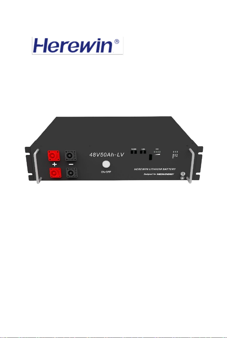
48V/50Ah is a 48V 50Ah household energy storage battery pack with LED visual
display, using the new high-energy batteries and advanced battery management system
to provide plenty of power to support most appliances found in the home, office,
garage/shed or workplace, such as TVs, stereos, video games, lights, fans, laptops,
phones and power tools. It can be used on-grid and off-grid in remote villages/districts
with inverter and controller and connect with the solar panels on the roof to store the
solar energy which can be used at night.
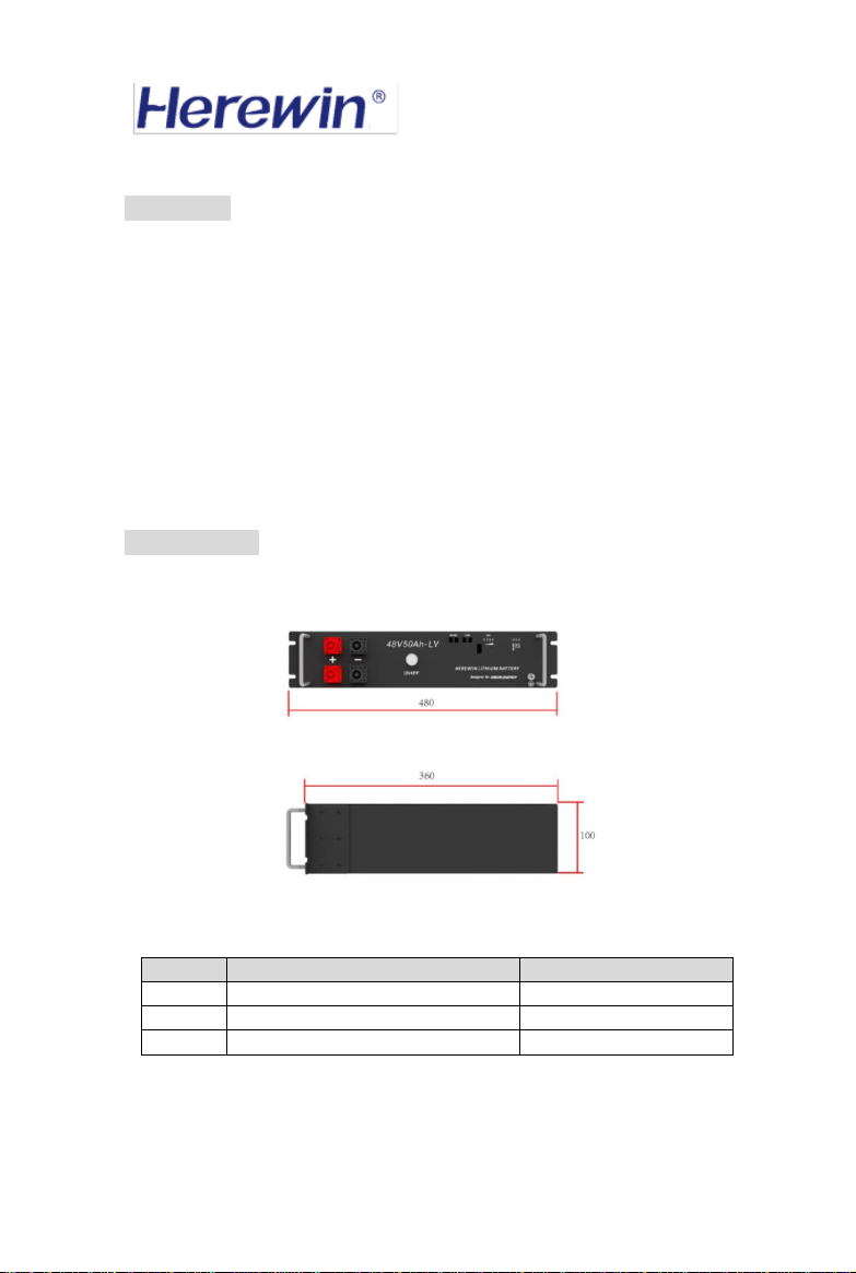
2. Appearance
Figure 1 Product Appearance and Size
No.
Items
Specification
1
Shell Material
Metal plate
2
Shell color
Black
3
Battery Dimension (mm) L*H*D
480*100*360
Table 1 Brief Introduction of Product

ShenzhenHerewinTechnologyCo.,Ltd.
3
3.General Structure Description
Figure 2 Functional Description of the Front Panel
①SWITCH
The total battery switch, press the switch, turn on the battery output.
②CAPACITY indicator
Four white LEDs perform a four-segment SOC indication, with the LEDs from left to
right representing the SOC from low to high. For details on the definition of SOC, see
《Table 2: Correspondence Table between Battery LED and SOC 》
③ALRM indicator
Red LED flashing to show the battery has alarm, and lighting to show the battery is
under protection.
④RS485 indicator
Lighting to show RS485 had connected.
⑤CAN indicator
Lighting to show CAN had connected.
⑥CAN port
Follow CAN protocol, for output batteries CAN information. The CAN-1 and CAN-2
ports have the same pin assignments and functions.
⑦RS485 port
Follow RS485 protocol, for output batteries RS485 information. The RS485-1 and
RS485-2 ports have the same pin assignments and functions.
⑧Battery port+
The output port of battery positive, to connect the positive of the inverter.
⑨Battery port-
The output port of battery negative, to connect the negative of the inverter.
①
②
③
④
⑤
⑥
⑧
⑦
⑨
ShenzhenHerewinTechnologyCo.,Ltd.
4
4.List of Accessories
NO.
Name
Quantity
Accessories Picture
Remarks
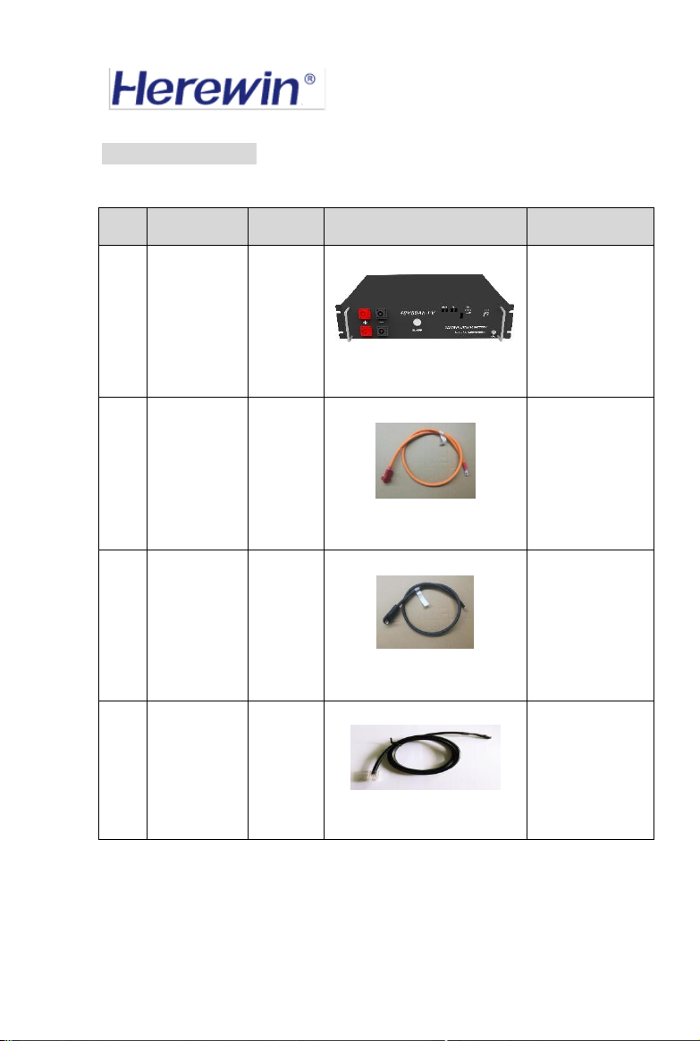
1#
48V/50Ah
battery
module
X1
Standard
accessories
2#
output
positive pole
line
X1
Standard
accessories, line
length:1000mm/
section 25 mm2
(120A max)
3#
output
negative pole
line
X1
Standard
accessories, line
length:1000mm
4#
output
communication
line
X1
Standard
accessories, line
length:1000mm
ShenzhenHerewinTechnologyCo.,Ltd.
5
Table 2 Catalogue of Accessories
Instructions:
5 # parallel positive pole line, 6 # parallel negative pole line and 7 # parallel
communication line are only needed in parallel operation mode of battery module.
Battery module is not needed in single-machine operation mode.
The number of these three cables is equal to the number of battery parallel machines
minus one. For example, when users use two modules in parallel, you need to use one 5
# parallel positive polar line, one 6 # parallel negative pole line and one 7 # parallel
communication line .
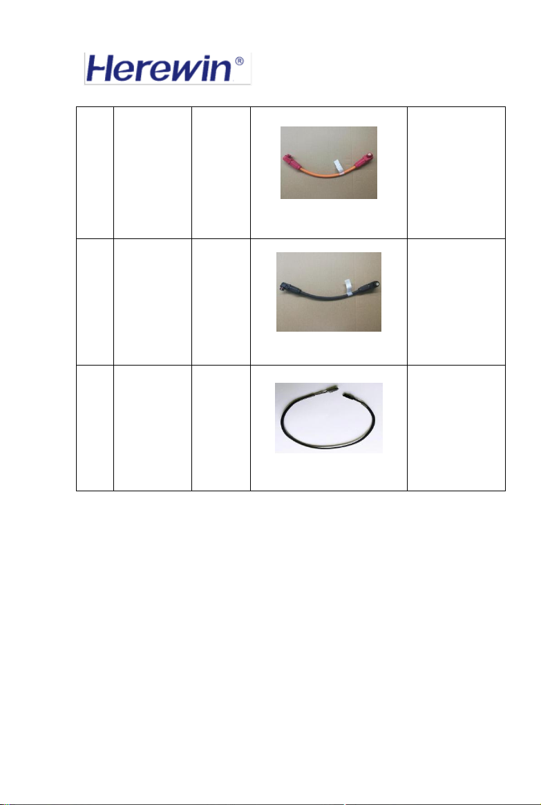
5#
Parallel
positive polar
line
number
of
parallel
machines
- 1
Selection of
accessories,line
length:350mm
6#
Parallel
negative pole
line
number
of
parallel
machines
- 1
Selection of
accessories, line
length:350mm
7#
Parallel
communication
line
number
of
parallel
machines
- 1
Selection of
accessories ,line
length:350mm
ShenzhenHerewinTechnologyCo.,Ltd.
6
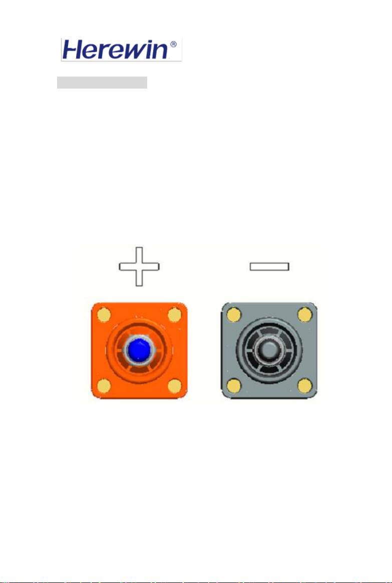
5.Electrical Interface
1. Battery+, Battery- port
The battery pack has two batteries output interfaces, distributed on the left side of the
battery panel, which are Power+ and Power-. These two interfaces belong to the parallel
relationship in the internal and electrical connection of the battery. Connected to the
inverter, the battery pack can be charged or discharged.
Figure 3 Battery+, Battery- port Interface Pin Distribution Diagram

ShenzhenHerewinTechnologyCo.,Ltd.
7
Table 3 Description of Battery Positive and Negative Pole Output Interface
2. Communication port
Two sets of 2PIN sockets are used in the battery pack. RS485 signal is in the socket.
RS485-1 and RS485-2 have the same function.
Two sets of 2PIN sockets are used in the battery pack. There are CAN signals in the
sockets. CAN-1 and CAN-2 have the same functions.
The CAN_H and CAN_L in the socket are connected with the inverter. They follow the
CAN protocol and are used to transmit the information and data of the battery. The CAN
matching resistor is required to installed on the device side.
RS485A and RS485B in the socket can be connected with PC computer, and follow the
RS485 protocol for battery package monitoring or firmware upgrade.
Battery-,
Battery+ port
-
battery
output
negative
pole
negative pole for charging
input or discharge output of
battery pack
terminal
color: black
-
battery
output
negative
pole
negative pole for charging
input or discharge output of
battery pack
terminal
color: black
+
battery
output
positive pole
positive pole for charging
input or discharge output of
battery pack
terminal
color: red
+
battery
output
positive pole
positive pole for charging
input or discharge output of
battery pack
terminal
color: red

ShenzhenHerewinTechnologyCo.,Ltd.
8
Table 4: Definition of Circuit Board Communication Interface
Note: NC indicates pin overhang.
3.LED Indicator
The LED indicator on the battery panel includes CAN operation indicator, RS485
operation indicator, ALARM alarm indicator and power indicator.
CAN Operating Indicator Light: white light, when battery pack is turned on, it will light
up; after shutdown, it will be extinguished.
RS485 Operating Indicator Light: white light, when battery pack is turned on, it will
light up; after shutdown, it will be extinguished.
ALM alarm light: red light, when the battery has an alarm, it will light; when the alarm is
lifted, it will be extinguished.
SOC power indicator light: white light, LED light from bottom to top is LED 1, LED 2,
LED 3, LED 4, indicating SOC power from low to high.
Interface
Type
Pin
Name
Pin Distribution
Communication port
CAN
Pin 1
CAN_H
Pin 2
CAN_L
Pin 1
CAN_H
Pin 2
CAN_L
RS485
Pin 1
RS485A
Pin 2
RS485B
Pin 1
RS485A
Pin 2
RS485B
1
2

ShenzhenHerewinTechnologyCo.,Ltd.
9
Figure 4 Indicator LED distribution diagram
Distribution of LED Indicators
Table 5 Implications of Electricity Indicators
6.Technical Specifications
Table 6 Product Specifications
LED1
LED2
LED3
LED4
SOC Volume of Battery Pack
●
○
○
○
≥25%
●
●
○
○
≥50%
●
●
●
○
≥75%
●
●
●
●
=100%
●represents LED lighting;○represents LED extinguishing.
Basic Parameters
48V/50Ah
Nominal capacity
50Ah
Nominal voltage
48V
Type
LiFeP04
Energy (KWh)
2.4KWh
Charge cut-off voltage (V)
54V
Charge current (A)
Recommended 25A
Discharge current (A)
Recommended 25A
Max. Pulse Current (A)
100A (Peaked@15S)
ShenzhenHerewinTechnologyCo.,Ltd.
10
7.Battery Single Machine Use
Discharge cut-off voltage(V)
45V
Working temperature
0℃ ~ +50℃charging
0℃ ~ +50℃discharging
Storage temperature
-20℃ ~ + 60℃
Max. size(mm) L*H*D
450*100*360 mm(IP20)
Weight (Kg)
25000g±500g
Color
Black
Communication
CAN/RS485
Safety Warning:
1. When the battery is not in use, please turn off the battery in time to avoid
excessive discharge of the battery, which will affect the battery life.
2. Please connect the battery pack when the power switch of the battery pack is
closed.
3. After installation, please make sure the connection of wires is correct before
turning on the power switch.
4. The battery contains high voltage. Do not operate them by non-professionals.
5. Please wear insulating gloves and provide necessary protection.

ShenzhenHerewinTechnologyCo.,Ltd.
11
1.Power line connection
Turn off the battery main power switch, use "2 # output positive pole line" to connect the
battery output Battery + with the positive pole of the inverter battery port, and use "3 #
output negative pole line" to connect the battery output Battery - with the negative pole
of the inverter battery port, the red is positive pole and the black is negative pole.
Attentions:
Negative and positive poles should not be reversed. Red is positive and black is negative.
When pulling out the battery output line, the lock button on the plug of the output line
must be pressed.
2.Communication Line Connection
The CAN port on the battery panel is connected to the communication interface of the
inverter by using "4 # Output Communication Line".
3.Turn on the battery
When ON/OFF is pressed, the switch will lock itself at the press position and wait a few
seconds. The output of the battery will be turned on. At this time, the battery can be
charged or discharged.
4.Turn off the battery
When the ON/OFF of the battery is pressed again, the switch will be reset, the battery
will be turned off and the output will be turned off.
Please connect the power terminal when the battery is turned off, make sure the wiring
is correct before turning on the power.

ShenzhenHerewinTechnologyCo.,Ltd.
12
Battery PACK Start-up:
1. Start-up step
1.1 Turn off battery PACK power supply
Turn off The button of battery PACK. Press down to turn on, pop-up to turn off.
usually, the factory is in a turn off state.
1.2 Wire connection
a) Connect the DC power wire of battery PACK to PCS.
b) Connect the CAN communication wires of battery PACK to PCS.
1.3 Start-up
a) Start-up PCS (Turn on DC and AC switch)
b) Turn on the ON/OFF button of the battery PACK and the battery PACK will start.
It takes 120 seconds to start the system. During the start -up process of battery PACK,
relevant commands will be sent to PCs through CAN to maintain effective
connection with PCS. At the same time, battery PACK will detect PCS
communication commands.
2. Start up failure
a) Communication failure
When the battery PACK does not receive the PCS communication command within
80 s interval, the battery PACK will turn off its output(power circuit)and wait for the
PCS communication connection.
b) Start-up surge protection
The test shows that PCS has very large surge current when it starts, especially when
it starts for the first time. Our BMS has adopted a lot of processing methods, but
sometimes the first boot, BMS may still fail to start.
If BMS fails to start, we can try to restart the system in one of the following two ways:
①Let PCS send 0x8848 (ID-0x305, DATA-0000 0000 0000 8848) on the last word of
DATA of CAN ID0x305 to restart BMS system.
②Release the ON/OFF button of the BMS to off the BMS and press it again later to
restart the BMS.

ShenzhenHerewinTechnologyCo.,Ltd.
13
8 .Parallels Using
1.Connect inverter
Turn off the battery, use the wires to connect the inverter terminal and battery terminal
(red for positive, black for negative)
Use the Communication cable to connect the CAN-1 or CAN-2 interface of the battery
pack to the communication port of the device. For the pin definition of the CAN and
RS485 port, see 《Table 7: Definition of Communication Port 》.
Safety Warning:
1. Parallel connection of the battery pack is only used to prolong the working time
of equipment, not to increase the output power of batteries, so the maximum
recommended charging current after parallel connection of batteries is limited to
25A, and the maximum recommended discharge current is limited to 25A.
2. Before parallel connection of the battery pack, please measure the output
voltage of each batteries. Parallel operation is prohibited if the voltage difference
between the batteries exceeds 2.5V. Please charge the battery pack with lower
voltage with charger or discharge the battery pack with higher voltage with load
until the voltage difference between the battery pack and other batteries is less
than 2.5V.
3. Please connect all batteries when the power switch is off.
4. After installation, please make sure the connection is correct before turning on
the power switch.
5. When the battery is not in use, please turn off the battery in time to avoid
excessive discharge of the battery, which will affect the battery life.
6. Batteries contain high voltage. Do not operate them by non-professionals.
7. Please wear insulating gloves and provide necessary protection.
ShenzhenHerewinTechnologyCo.,Ltd.
14
1.Parallel Parameter Setting of the Battery
Set up the battery pack that needs to be connected in parallel to the BMS software on the
PC computer via RS485.
Configure[BMS Address] parameter for each battery. The address of each battery is not
duplicated. The address of each battery is defined as 0 for the host and the address of 1 ~
7 for the slave.
2.Communication Line Connection
The communication ports that need to be connected in parallel will be connected in
parallel using the “7# parallel communication line” to connect the communication port
of one of the battery to the next adjacent group of battery port, and the communication
ports of all battery modules will be connected in this order.
The wiring method is detailed in "48V/50Ah parallel wiring diagram".
The communication interface of the device end should be equipped with CAN matching
resistor.
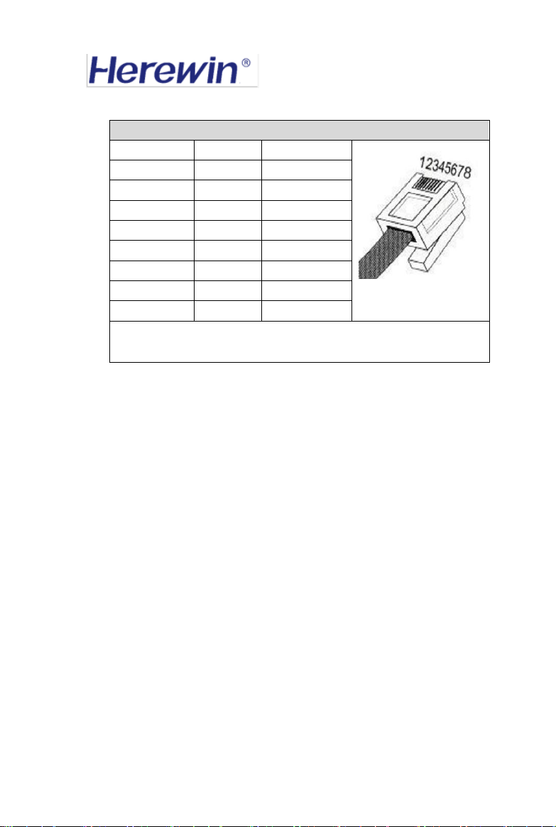
Table7:Definition of Communication Port
Pin of RJ45
CAN port
RS485 port
Pin 1
CAN_H
RS485_A
Pin 2
CAN_L
RS485_B
Pin 3
NC
NC
Pin 4
NC
NC
Pin 5
NC
NC
Pin 6
NC
NC
Pin 7
NC
NC
Pin 8
NC
NC
The CAN-1/RS485-1 and CAN-2/RS485-2 ports have the same pin
assignments and functions.

ShenzhenHerewinTechnologyCo.,Ltd.
15
3. Power line connection
Before parallel connection of power lines, make sure that the power switch of each
battery is turned off.
Each battery has two positive and two negative extreme ports. One of the positive poles
of the battery module is connected to the positive pole of the next group of adjacent
battery by using the
“
5 # parallel positive pole line
”
,and one of the negative poles of
the battery module is connected to the negative pole of the next group of adjacent battery
by using the “6 # parallel negative pole line”.The positive ports of all battery modules
are parallel in sequence, and the negative ports of all battery modules are connected in
parallel. Finally, the positive and negative ports of a group of battery modules are
connected to the inverters by using "2 # output positive pole line" and "3 # output
negative pole line".
The wiring method is detailed in "48V/50Ah parallel wiring diagram".
The parallel connection of battery packs is only used to prolong the working time
of the equipment, not to increase the output power of the battery, so the maximum
recommended charging current of the battery packs after parallel connection is limited to
25A and the recommended maximum discharge current is limited to 25A.
4.Turn on the battery
When ON/OFF is pressed, the switch will lock itself at the press position and wait a few
seconds, the output of the battery will be turned on. At this time, the battery can be
charged or discharged.
5.Turn off the battery
When the ON/OFF of the battery is pressed again, the switch will be reset, the battery
will be turned off and the output will be turned off.
ShenzhenHerewinTechnologyCo.,Ltd.
16
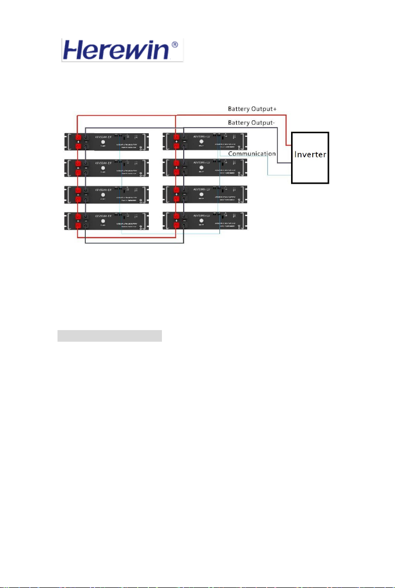
6.48V/50Ah Parallel Connection Diagram
Figure 5 - Battery Parallel Connection Diagram (25A by batteries)
Note: Minimum space of 25mm and heat dissipation between each battery is necessary
to provide ventilation.
9. Charging instructions
1. The charging current and charging voltage must not exceed the maximum value
specified in this user manual.
2. The charging temperature must not exceed the charging temperature range specified in
this user manual.
3. It is forbidden to charge the battery for a long time. It is forbidden to reverse charge
the battery.
4. The charging parameter setting of the charger should meet the requirements of the
technical specifications of this product.
5. Use current, voltage, and temperature ranges beyond the technical specifications of the
product, which may cause problems with charge, discharge, mechanical, and safety
performance of the battery.

ShenzhenHerewinTechnologyCo.,Ltd.
17
10. Storage
1. The battery pack storage temperature must be in the range of -20 ° C ~ +60 ° C.
2. For long-term storage of the battery pack, it must be recharged once for more than one
months. It must be placed in an environment with a temperature of 23 ± 5 ° C and a
humidity of 5-85 % RH. Recommended storage voltage is 48.75~51.09V.
11.Transport
The battery should be packed in a box under the state of charge (15~30% state of
charge) for transportation. During transportation, it should be protected from severe
vibration, shock or extrusion to prevent sun and rain. It should be applied to cars, trains,
ships and airplanes. Wait for ordinary transportation.
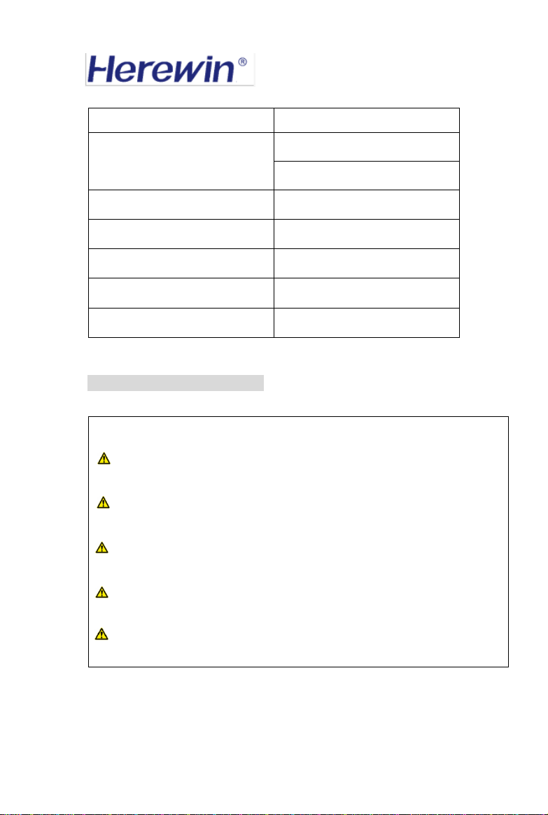
12. Warnings and Precautions
Please read the following precautions carefully before use to ensure proper use
and installation. The company is not responsible for any problems arising from
violations of the following matters.
Danger !
Do not put the battery into fire or heat the battery;
Do not put the battery into the water or wet it; soak the liquid, such as
sea water, beverages, beer, etc.;
Do not use or store batteries near heat sources such as fire or heaters;
The parameters of the charger should meet the requirements of the

ShenzhenHerewinTechnologyCo.,Ltd.
18
technical specifications of this product;
Do not reverse the positive and negative poles;
Do not connect the battery directly to a wall outlet or a car cigarette
lighter socket;
Do not pierce the battery case with nails or other sharp objects, and
prohibit hammering or pedaling the battery;
Direct soldering of battery terminals is prohibited;
Do not disassemble the battery in any way;
Do not charge the battery under fire or extreme heat;
Do not strike, throw or subject the battery to mechanical shocks;
Do not short-circuit the positive and negative terminals of the battery
with wires or other metal objects. Do not transport or store the battery with
necklaces, hair clips or other metal objects.
Warning !
Normal discharging temperature range is 0℃ to 50℃. Under 5℃, battery
capacity will drop dramatically, which will result in reduced usage time;
Normal charging temperature range is 0℃ to 50℃;
Do not charge the battery under 0℃;
Do not use in temperature above 50℃;
Do not use the battery of upside down;
Do not reverse charge and discharge terminal;
Do not put into water;
Do not place the battery in a microwave or pressure vessel;
Do not use a damaged battery;

ShenzhenHerewinTechnologyCo.,Ltd.
19
The battery may be damaged during the transportation process due to
impact or the like. If the battery is found to have any abnormal characteristics,
such as damage to the battery plastic seal, damage to the outer casing, smell of
electrolyte gas, electrolyte leakage, etc., the battery shall not be used;
Do not use if the battery emits odor, heat, deformation, discoloration or
any other abnormality; if the battery is being used or charged, immediately
stop using it from the power off; if the battery leaks or emits an odor,
immediately away from the fire source to avoid fire. Or explosion;
If the electrolyte leaks into the eyes, do not rub it, rinse with water or
seek medical attention immediately. If left untreated, your eyes will be hurt.
Precautions !
Do not use batteries in extremely hot environments, such as in direct
sunlight or in hot days. Otherwise, the battery will overheat and may catch
fire (ignition), which will affect the performance of the battery and shorten the
battery life;
Use the battery only on the specified device;
If the battery leaks and the electrolyte gets on the skin or clothing,
immediately wash the affected area with running water, otherwise it may
cause skin irritation;
Read the battery unit manual to properly install and use the battery;
If the battery output terminal is dirty, wipe it off with an eraser or a dry
cloth before use. When the battery is electrically connected to the device, the
electrical connection point needs to be reliable and firm, and the screw needs
to be tightened. Otherwise, the contact may be poor, which may cause energy
loss. In severe cases, it may cause safety problems.
Table of contents
Popular Camera Accessories manuals by other brands


Trojan
Trojan GC2 48V quick start guide

Calumet
Calumet 7100 Series CK7114 operating instructions

Ropox
Ropox 4Single Series User manual and installation instructions

Cambo
Cambo Wide DS Digital Series Main operating instructions

Samsung
Samsung SHG-120 Specification sheet

Ryobi
Ryobi BPL-1820 Owner's operating manual