HeroSpeed OWL256 User manual

Thermal Smart IP Camera
Quick Start Guide
Please read this manual carefully and keep it properly before using our
network camera products.
Related tools and documents of products, please download from
http://www.herospeed.net.

Statement
Thank you for using our products, please read this manual carefully
before trying.
This manual is applicable to network series products.
This manual may contain information that is technically inaccurate,
inconsistent in the product's function and operation, or in a typographical
error. Our company will update the context in the manual according to the
enhancement of product features. Updated content will be added in the
new version of this manual without further notice.
If there is manual description of the product does not match with the
physical, in order to prevail in kind.
Safety Precautions
Please do not place the device in an environment with corrosive gas, which
will damage the device.
Please do not place the device in places exposed to direct sunlight, poor
ventilation, or near heat sources such as a heater (ignoring this item may
cause fire hazard).
Please do not install the device in extremely cold places, such as the air
outlet of an air conditioner.
Please do not aim the lens at strong light sources, such as the sun,
fluorescent lamps and other high-temperature targets; otherwise it will
cause damage to the lens or thermal imaging detector. If you must aim the
lens at a strong light source, please turn on "Anti-burn Protection ".
Please do not aim the lens at a cold source, such as air conditioning outlets,
cold drinks, ice, etc.
Please keep the device installed in a stable place, taking care to avoid the
product falling or being hit by falling objects.
Please use a very soft dry cloth or other alternatives to wipe the surface,
do not use alkaline cleaners, and avoid scratching the device with hard
objects.
Please understand that you are responsible for properly configuring all
passwords and other product-related security settings, and keeping your
user name and password properly.

The following exemptions or limitations of liability, please pay special
attention to:
Disclaimer
As a result of the following reasons, if the product interrupts or terminates
the service for any of the following reasons, the company shall not be
liable for personal injury or property damage to you or a third party.
Failure to install or use properly as required; for the sake of national or
public interest; force majeure; your own or third-party reasons (including
but not limited to the use of third-party products, software or
components, etc.
The company has not expressed or implied that this product is applicable
to special purpose.This product may not be used in medical / safety
equipment or other applications where there is a breakdown of the
product that could result in life-threatening or personal injury, as well as
hazardous or non-humanitarian hazards such as weapons of mass
destruction, biological and chemical weapons, nuclear explosions or any
unsafe use of nuclear energy use. Any loss or liability arising out of the
above use will be at your own risk.
This product, when properly installed and used, can detect unauthorized
intrusion during a particular delight but can not avoid accidents or
personal injury or property damage. In your daily life, you should be vigilant
and strengthen your safety awareness.
The Company is not responsible for any indirect, incidental, special
punitive damages, claims, loss of property or loss of any data or
documents. To the maximum extent permitted by law, the liability for
compensation of company is not exceed than the amount you paid for this
product.
1. Product Introduction
Thermal imaging binocular intelligent network camera is a new thermal
imaging network camera that integrates network remote monitoring
functions, face recognition algorithms, video server functions and
high-definition camera functions. It supports visible light and thermal
imaging dual video output, human body temperature measurement, face
recognition capture and other functions.
The camera has a built-in temperature sensor, which has the characteris-
tics of temperature measurement with high sensitivity, intuitionistic heat
map, fast speed, no interference with the measured target, and safe use.
The device can measure the temperature of multiple people at the same
time, quickly screen out persons with abnormal temperature, and help
users prevent epidemics.
Due to its characteristics, the camera can be widely used in places that
require small-scale thermal imaging monitoring, such as schools, office
buildings, museums, shopping malls, banks, stations and other places with
large flow of people at the entrance and exit.
1.1. Product Description
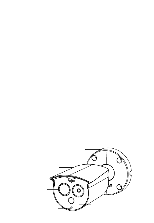
1.2. Introduction Of Product Appearance
Housing
Mounting brackets
Lens
Flash lamp
Loudspeaker
Temperature
measurement module
MIC
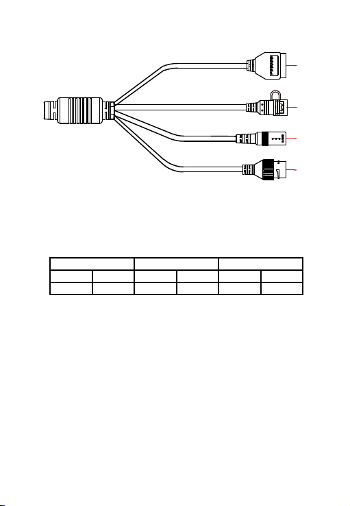
1.3. Cable Description
① Alarm interface: including alarm input and alarm output, a group of inputs,
a group of outputs and RS485 (used to connect external devices with
RS-485 interface).
② Reset interface: Long press the reset button for 10 seconds, the device
will be restored to the factory default parameters.
③ Power interface: support DC12V, POE power supply. If it is DC12V, please
connect the positive and negative power supply correctly.
④ Network port interface: used to access Ethernet through RJ45 and power
the device through POE.
Alarm Input Alarm Output RS485
123456
+ - A B 485+ 485-
④
③
①
②
2. Product Installation
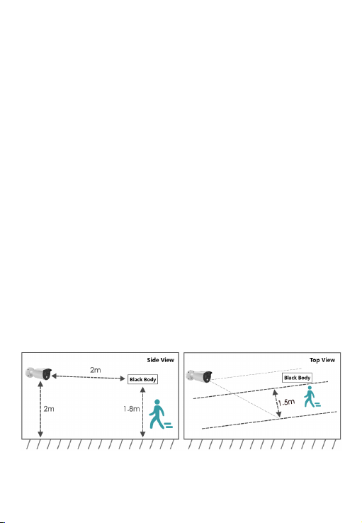
2.1. Installation Location Selection
(1) The camera is set up right in front of the passage to capture the face.
(2) The recommended installation height is about 2 meters, and the
recommended viewing angle of the camera is 0~5 degrees.
(3) In order to ensure the effect of body temperature detection, the distance
between device and personnel collection point should be within 2 meters
(range 0.25~3 meters).
2.2. Installation Environment Standard
(1) Illumination requirements: no backlight, no obvious reflection on the face,
uniform light and no shadows. In addition, if the face in the lens is not bright
enough, in order to ensure sufficient lighting on the scene when capturing
faces, it is recommended that lighting equipment needs to be added
accordingly to fill up the face light (generally 250~800 Lux).
(2) Requirements for light and wind: It is recommended that the device be
installed indoors to ensure that there is no wind or direct sunlight between
the device and personnel, and avoid the phenomenon of excessively low and
high temperature measurement caused by blowing and direct sunlight.

2.3. Instructions Before Installation
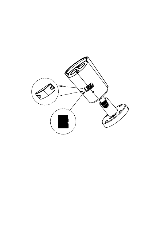
2.4. TF Card Installation
If you need to use an TF card to store video, pictures and other data, please
install the TF card before installing the device. If you don't need to use TF
card to store data, please skip this chapter.
After installing the TF card in the IPC, you need to install it
according to the method before disassembly, otherwise it
will affect the airtightness of the camera and thus affect
the normal use of the device.
Warning
The wall to be installed should have a certain thickness and can withstand at
least 4 times the weight of the camera and mounting accessories.
If the device is installed on a concrete wall or ceiling, you need to install
expansion screws before installing the bracket. (Please note that
the holes of the expansion screws must be consistent with the mounting
bracket)
If the device is installed on a wooden wall, the bracket can be directly
installed on the wall with self-tapping screws.
When you pick up the camera, do not directly pull the cable at the rear of
the camera. Otherwise, it may damage the waterproof performance of the
camera or cause circuit problems.
Before installation, please check whether the equipment in the packing box
is intact and all accessories are complete.
The camera supports wall mounting, ceiling mounting and tripod mounting,
and different installation methods can be selected according to different
installation environments.
2.5. Install the IPC
Step 1 There is a TF card slot on the back of the device, then use a phillips
screwdriver to unscrew the TF card slot cover.
Step 2: Insert the TF card into the card slot slowly, and when you hear a
"click" sound, the installation is successful.
Step 3 Close the TF card cover and tighten the screws.
①
②
③
2.5.1. Wall Mounting
Note: Wall mounting and ceiling mounting are the same. For ceiling mounting,
please refer to the wall mounting method.
Step 1 Choose a suitable installation wall, then paste the attached installation
sticker on the wall. Punch 4 φ6mm installation holes according to the label
on the sticker, then insert the expansion tube into the hole.
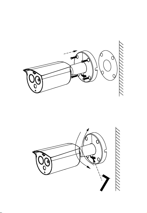
Step 3 Use a hexagon wrench to loosen the fixing screws, then adjust the
camera to a proper angle, and tighten the fixing screws to complete the
installation.
Step 2 Arrange and connect the power cables, network cables and other
cables of the device, and insulate the power cables. Clip the cable into the
cable outlet. Align the base hole with the sticker hole, and fix the device to
the wall with screws.

After the IPC is installed, you need to configure functions and set parame-
ters for it. You can configure related functions through the browser.
3. Instructions
Align the screws on the top of the tripod with the mounting holes on the
bottom of the camera and lock the screws to fix.
2.5.2. Tripod Mounting
Tripod hole
3.1. Network Setting
The default IP of all cameras is 192.168.1.168. The IPv4 address of the
computer must be in the same network segment as the IP address of the

The network configuration steps are as follows:
Step 1: Open [ Search Tool] (Version 7.2.45.6 and above, please install
Search Tool from http://www.herospeed.net).
Step 2: Check 192.168.1.168.
Step 3: Modify the relevant network parameters such as IP on the right side of
the interface.
(1) Add the same network segment IP as 192.168.1.168 (camera factory
default IP) in the computer, such as 192.168.1.165.
Prepare the network configuration:
Steps to add an IP address to the Windows system:
Step 1: Click [ ] Start → [Control Panel] → [Network and Sharing
Center] → [Local Network] → [Properties] → [Internet Protocol Version 4
(TCP/IPv4)] → [Advanced] to enter the advanced TCP/IP setting interface.
Steps 2: Click [Add] in the IP address (R) position, enter the IP address as
192.168.1.165 and the subnet mask 255.255.255.0, and click [Add] →[OK]
→ [OK] → [OK].
(2) Connect camera and PC by network cable in the same LAN, power on.
Connecting as following (PoE switch, camera, PC connection photo).
IP camera. To enable the camera to access the network smoothly, plan the
available IP network segments based on the actual network environment.
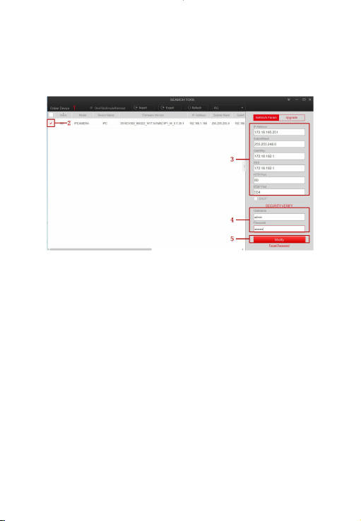
Step 6: Click [Refresh] to find the IP address that has been modified, which
means that the network configuration is successful.
NOTE: When configuring network parameters, ensure that the IPC address and
the computer's IPv4 address are on the same network segment.
Step 1: Open the IE browser, enter the IP address of IP Camera (if the IP has
not been modified, please enter the default address http://192.168.1.168),
and press [Enter].
Step 2: Click [Download], download the plug-in, close the browser, and follow
the prompts to install the plug-in.
Step 3: Enter the user name (admin) and password (admin) of the device,
and click [Login].
3.2. Login
Step 4: Enter the user name (default is admin) and password (default is admin)
of the device.
Step 5: Click [Modify] → [Confirm].

3.4. Parameter Configuration
Enter real-time preview interface after login. Select the play window, click
the channel on the left side of the interface, and the play window will play
real-time video.
3.3. Real-time Preview
Click [Configuration] to enter the parameter configuration interface of the
device, which includes local configuration, system, network, video, image,
events, temperature measurement and other functional configurations.
Users can selectively set these functions according to actual application
scenarios to achieve the best monitoring effect.

Step 1: On the main interface, click [Configuration] → [Temperature
measure] → [Temperature measure] to enter the temperature measurement
basic setup interface.
3.5. Temperature Measure Configuration
Step 2: Turn on the temperature measurement function to configure the
relevant temperature measurement parameters of Camera 02, and click
[Save].
Step 3: Click [Temperature measurement config] to configure the related
temperature measurement parameters of Camera 01, and click [Save].

Step 4: Select [Camera 02], draw the bold point (if there is a black body) and
reference point, configure related parameters (shutter parameters,
temperature compensation, etc.), and click [Save].

[Draw black body point] Draw at the position of the black body.
[Drawing reference point] Choose a place close to the current ambient
temperature and preferably not blocked by people to draw the reference
point.
Step 5: Select [Camera 01],and Click [Linkage Method] → [Arming Schedule]
to set the arming time.
Step 6: Click [Linkage Method] and set the linkage method as required.
Step 7: Click [Save] to complete the configuration.
Step 1: Open your browser and visit http://www.herospeed.net/.
Step 2: Click [PC Client] → [iVMS330 (Windows)] or [iVMS330 (Mac)] to
download the latest version of the video management system [iVMS330].
Step 3: Follow the prompts to install and add devices to view and manage
the devices.
3.6. iVMS330 Client Access
Infrared video previewVisible light video preview
Body temperature
distribution
Abnormal capture
record
Face capture record
Toolbar
Device List
Table of contents


