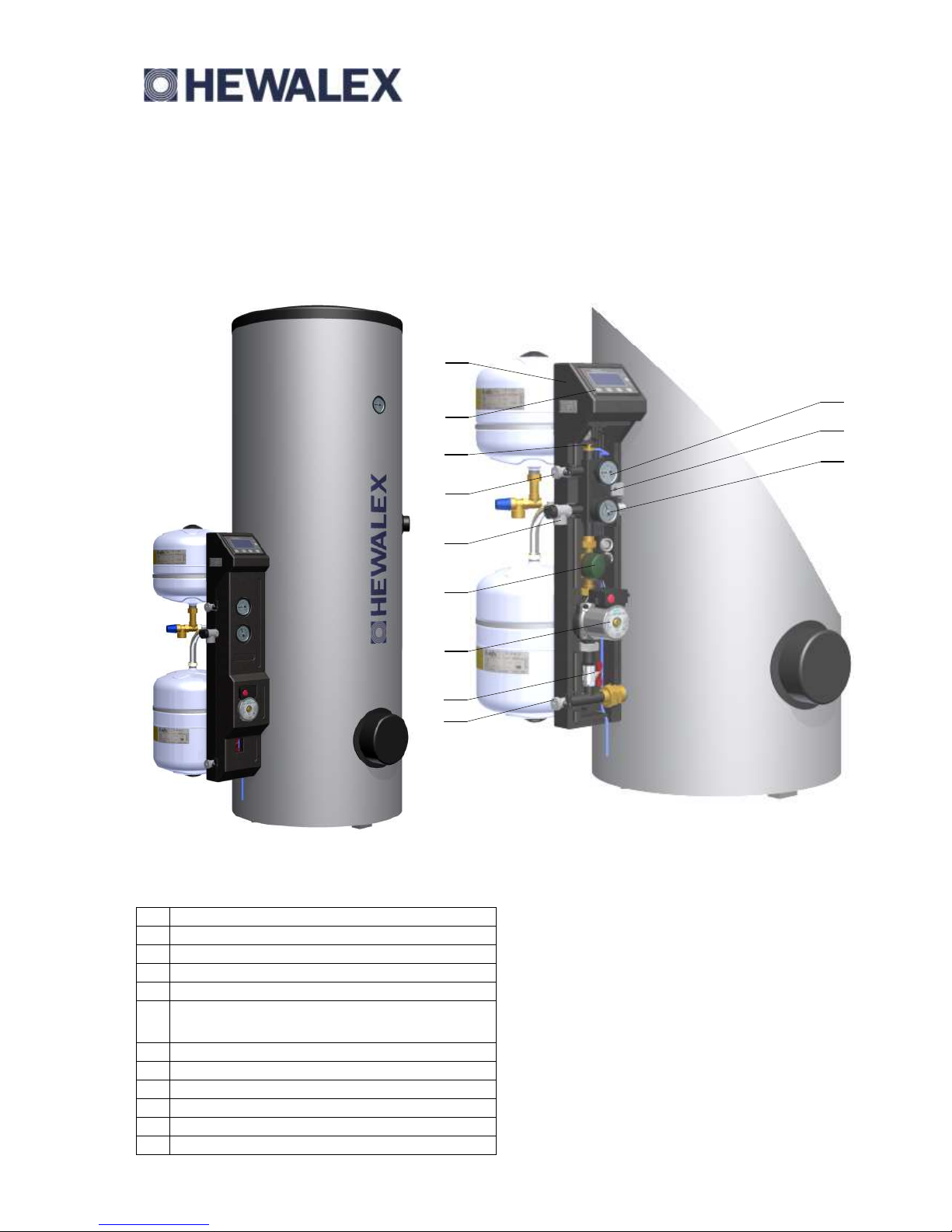
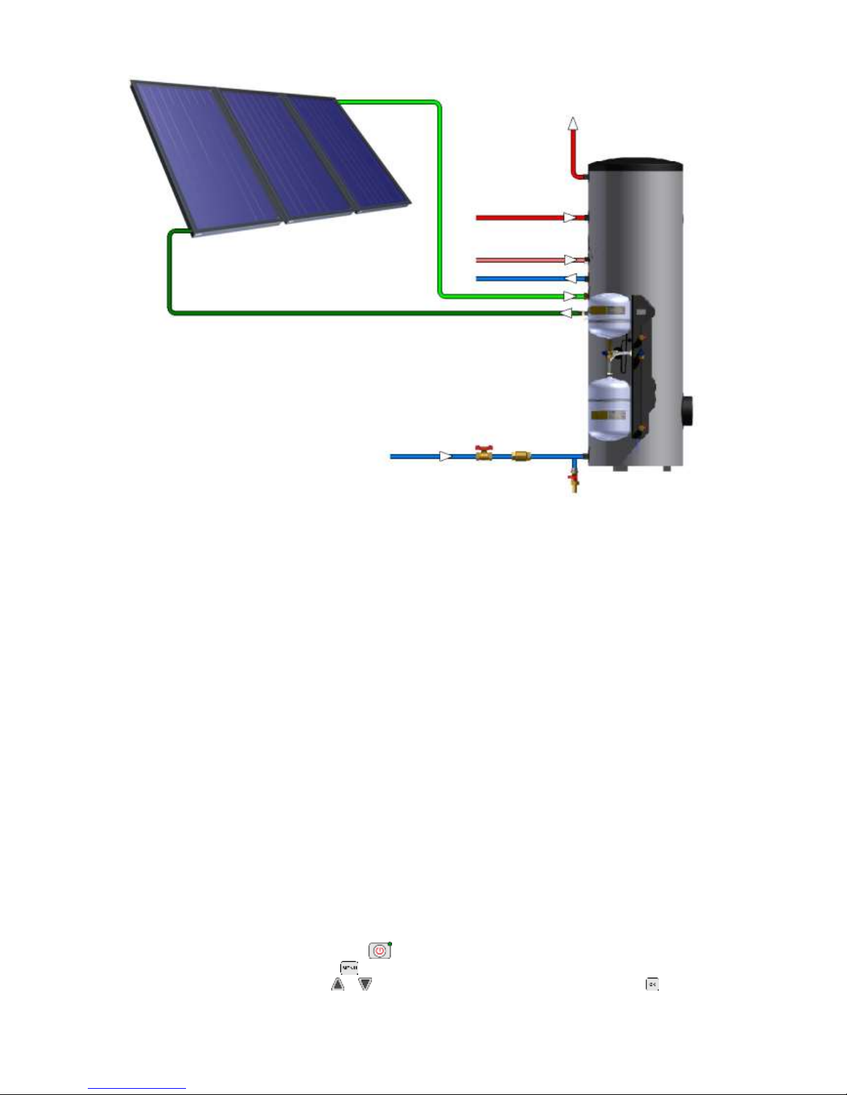
Hewalex KOMPAKT 300HB User manual

Popular Boiler manuals by other brands

SAS
SAS BIO SOLID 19 Operation and maintenance manual

Nibe
Nibe VEDEX 1000 Installation and maintenance instructions

ECR
ECR DUNKIRK ESC3100 Installation, operation & maintenance manual

LAMBORGHINI
LAMBORGHINI MEGA 92 Operating, installation and maintenance instructions

Ravenheat
Ravenheat HE 25 C COMPACT Instructions for use installation and servicing

Fröling
Fröling Lambdatronic SP 3200 Service manual

Flavel
Flavel RENAISSANCE RETRO FRRRF0MN Installation and maintenance instructions

Drazice
Drazice OKC 200 NTRR/SOL OPERATING AND INSTALLATION Manual

Devex
Devex X Boiler BD Series instruction manual

Saunier Duval
Saunier Duval Themaclassic F30E SB Instructions for use installation and servicing

Instanta
Instanta SureFlow Touch WMS6PB Installation and user instructions

Worcester
Worcester Greenstar 8000 Style GR8700iW 35 C Installation and maintenance instructions

thermital
thermital THC V E OIL BLU Series manual

Potterton
Potterton Cold HE A user guide

Danfoss
Danfoss 3 Series operating guide

Joannes
Joannes EPOCA 25-29 NS Installation and maintenance manual

Ariston
Ariston CLAS 28 FF Installation and servicing instructions

Viessmann
Viessmann Vitocrossal 300 CU3A Application guide