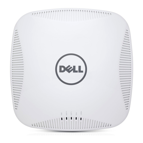
Hewlett Packard Enterprise AP-504 User manual

Aruba AP-5XX Wireless Access Points with ArubaOS FIPS Firmware FIPS 140-2 Level 2 Security Policy
Aruba AP-504, AP-505, AP-514, AP-
515, AP-534, AP-535 and AP-555
Wireless Access Points
with ArubaOS FIPS Firmware
Non-Proprietary Security Policy
FIPS 140-2 Level 2
Version 1.1
February 2021

Aruba AP-5XX Wireless Access Points with ArubaOS FIPS Firmware FIPS 140-2 Level 2 Security Policy
Copyright
© 2020 Hewlett Packard Enterprise Company. Hewlett Packard Enterprise Company trademarks
include , Aruba Networks®, Aruba Wireless Networks®, the registered Aruba the Mobile Edge Company
logo, Aruba Mobility Management System®, Mobile Edge Architecture®, People Move. Networks Must Follow®, RFProtect®,
Green Island®. All rights reserved. All other trademarks are the property of their respective owners.
Open Source Code
Certain Hewlett Packard Enterprise Company products include Open Source software code developed by third parties, including
software code subject to the GNU General Public License (GPL), GNU Lesser General Public License (LGPL), or other Open
Source Licenses. The Open Source code used can be found at this site:
http://www.arubanetworks.com/open_source
Legal Notice
The use of Aruba switching platforms and software, by all individuals or corporations, to terminate other vendors’ VPN client
devices constitutes complete acceptance of liability by that individual or corporation for this action and indemnifies, in full, Aruba.
from any and all legal actions that might be taken against it with respect to infringement of copyright on behalf of those vendors.
Warranty
This hardware product is protected by the standard Aruba warranty of one year parts/labor. For more information, refer to the
ARUBACARE SERVICE AND SUPPORT TERMS AND CONDITIONS.
Altering this device (such as painting it) voids the warranty.
www.arubanetworks.com
3333 Scott Blvd
Santa Clara, CA, USA 95054
Phone: 408.227.4500
Fax 408.227.4550

Aruba AP-5XX Wireless Access Points with ArubaOS FIPS Firmware FIPS 140-2 Level 2 Security Policy |3
Contents
1. Purpose of this Document ....................................................................................................................................7
1.1. Related Documents.......................................................................................................................................7
1.2. Additional Product Information....................................................................................................................7
1.3. Acronyms and Abbreviations........................................................................................................................8
2. Overview...............................................................................................................................................................9
2.1 AP-500 Series ................................................................................................................................................9
2.1.1 Physical Description............................................................................................................................11
2.1.2 Dimensions/Weight ............................................................................................................................11
2.1.3 Environmental.....................................................................................................................................11
2.1.4 Interfaces ............................................................................................................................................11
2.2 AP-510 Series ..............................................................................................................................................13
2.2.1 Physical Description............................................................................................................................15
2.2.2 Dimensions/Weight ............................................................................................................................15
2.2.3 Environmental.....................................................................................................................................15
2.2.4 Interfaces ............................................................................................................................................15
2.3 AP-530 Series ..............................................................................................................................................17
2.3.1 Physical Description............................................................................................................................18
2.3.2 Dimensions/Weight ............................................................................................................................19
2.3.3 Environmental.....................................................................................................................................19
2.3.4 Interfaces ............................................................................................................................................19
2.4 AP-550 Series ..............................................................................................................................................21
2.4.1 Physical Description............................................................................................................................22
2.4.2 Dimensions/Weight ............................................................................................................................22
2.4.3 Environmental.....................................................................................................................................22
2.4.4 Interfaces ............................................................................................................................................22
3. Module Objectives..............................................................................................................................................24
3.1. Security Levels ............................................................................................................................................24
4. Physical Security .................................................................................................................................................25
5. Operational Environment ...................................................................................................................................25
6. Logical Interfaces ................................................................................................................................................25
7. Roles, Authentication and Services ....................................................................................................................26
7.1 Crypto Officer Role .....................................................................................................................................26
7.2 User Role.....................................................................................................................................................28
7.3 Authentication Mechanisms.......................................................................................................................28
7.4 Unauthenticated Services...........................................................................................................................29
7.5 Services Available in Non-FIPS Mode .........................................................................................................29
8. Cryptographic Key Management ........................................................................................................................30
8.1. FIPS Approved Algorithms ..........................................................................................................................30
8.2. Non-FIPS Approved but Allowed Cryptographic Algorithms......................................................................33
8.3. Non-FIPS Approved Cryptographic Algorithms...........................................................................................33
9. Critical Security Parameters................................................................................................................................34
10. Self-Tests.........................................................................................................................................................37
11. Installing the Wireless Access Point................................................................................................................39
11.1. Pre-Installation Checklist ........................................................................................................................39

4| Aruba AP-5XX Wireless Access Points with ArubaOS FIPS Firmware FIPS 140-2 Level 2 Security Policy
11.2. Identifying Specific Installation Locations...............................................................................................39
11.3. Precautions .............................................................................................................................................40
11.4. Product Examination...............................................................................................................................40
11.5. Package Contents....................................................................................................................................40
12. Tamper-Evident Labels ...................................................................................................................................41
12.1. Reading TELs ...........................................................................................................................................41
12.2. Required TEL Locations...........................................................................................................................42
12.2.1 TELs Placement on the AP-504 ...........................................................................................................42
12.2.2 TELs Placement on the AP-505 ...........................................................................................................43
12.2.3 TELs Placement on the AP-514 ...........................................................................................................44
12.2.4 TELs Placement on the AP-515 ...........................................................................................................45
12.2.5 TELs Placement on the AP-534 ...........................................................................................................46
12.2.6 TELs Placement on the AP-535 ...........................................................................................................47
12.2.7. TELs Placement on the AP-555 ...........................................................................................................48
12.3. Applying TELs ..........................................................................................................................................49
12.4. Inspection/Testing of Physical Security Mechanisms.............................................................................49
13. Secure Operation............................................................................................................................................50
13.1. Crypto Officer Management...................................................................................................................51
13.2. User Guidance.........................................................................................................................................51
13.3. Setup and Configuration.........................................................................................................................51
13.4. Setting Up Your Wireless Access Point ...................................................................................................52
13.5. Enabling FIPS Mode on the Staging Controller.......................................................................................52
13.5.1. Enabling FIPS Mode on the Staging Controller with the CLI...............................................................52
13.6. Non-Approved FIPS Mode Configurations..............................................................................................53
13.7. Full Documentation ................................................................................................................................53

Aruba AP-5XX Wireless Access Points with ArubaOS FIPS Firmware FIPS 140-2 Level 2 Security Policy |5
Figures
Figure 1 - Aruba AP-504 Campus Access Point – Front ................................................................................................9
Figure 2 - Aruba AP-504 Campus Access Point – Back..................................................................................................9
Figure 3 - Aruba AP-505 Campus Access Point – Front ..............................................................................................10
Figure 4 - Aruba AP-505 Campus Access Point – Back................................................................................................10
Figure 5 - Aruba AP-500 Series Campus Access Point – Interfaces ............................................................................12
Figure 6 - Aruba AP-514 Campus Access Point – Front ..............................................................................................13
Figure 7 - Aruba AP-514 Campus Access Point – Back................................................................................................13
Figure 8 - Aruba AP-515 Campus Access Point – Front ..............................................................................................13
Figure 9 - Aruba AP-515 Campus Access Point – Back................................................................................................14
Figure 10 - Aruba AP-510 Series Campus Access Point – Interfaces ..........................................................................16
Figure 11 - Aruba AP-534 Campus Access Point – Front ............................................................................................17
Figure 12 - Aruba AP-534 Campus Access Point – Back..............................................................................................17
Figure 13 - Aruba AP-535 Campus Access Point – Front ............................................................................................17
Figure 14 - Aruba AP-535 Campus Access Point – Back..............................................................................................18
Figure 15 - Aruba AP-530 Series Campus Access Point – Interfaces ..........................................................................19
Figure 16 - Aruba AP-555 Campus Access Point – Front ............................................................................................21
Figure 17 - Aruba AP-555 Campus Access Point – Back..............................................................................................21
Figure 18 - Aruba AP-550 Series Campus Access Point – Interfaces ..........................................................................23
Figure 19 - Tamper-Evident Labels .............................................................................................................................41
Figure 20 – Top View of AP-504 with TELs..................................................................................................................42
Figure 21 – Bottom View of AP-504 with TELs ...........................................................................................................42
Figure 22 – Top View of AP-505 with TELs..................................................................................................................43
Figure 23 – Bottom View of Aruba AP-505 with TELs.................................................................................................43
Figure 24 – Top View of AP-514 with TELs..................................................................................................................44
Figure 25 – Bottom View of Aruba AP-514 with TELs.................................................................................................44
Figure 26 – Top View of AP-515 with TELs..................................................................................................................45
Figure 27 – Bottom View of Aruba AP-515 with TELs.................................................................................................45
Figure 28 – Top View of AP-534 with TELs..................................................................................................................46
Figure 29 – Bottom View of Aruba AP-534 with TELs.................................................................................................46
Figure 30 – Top View of AP-535 with TELs..................................................................................................................47
Figure 31 – Bottom View of Aruba AP-535 with TELs.................................................................................................47
Figure 32 – Top View of AP-555 with TELs..................................................................................................................48
Figure 33 – Bottom View of Aruba AP-555 with TELs.................................................................................................48

6| Aruba AP-5XX Wireless Access Points with ArubaOS FIPS Firmware FIPS 140-2 Level 2 Security Policy
Tables
Table 1 - AP-500 Series Status Indicator LEDs ............................................................................................................12
Table 2 - AP-510 Series Status Indicator LEDs ............................................................................................................16
Table 3 - AP-530 Series Status Indicator LEDs ............................................................................................................20
Table 4 - AP-550 Series Status Indicator LEDs ............................................................................................................23
Table 5 - Intended Level of Security ...........................................................................................................................24
Table 6 - FIPS 140-2 Logical Interfaces........................................................................................................................25
Table 7 - Crypto-Officer Services ................................................................................................................................27
Table 8 - Estimated Strength of Authentication Mechanisms....................................................................................28
Table 9 - ArubaOS OpenSSL Module CAVP Certificates..............................................................................................30
Table 10 - ArubaOS Crypto Module CAVP Certificates ...............................................................................................31
Table 11 - ArubaOS UBOOT Bootloader CAVP Certificates ........................................................................................32
Table 12 - CSPs/Keys Used in the Module ..................................................................................................................34
Table 13 - Inspection/Testing of Physical Security Mechanisms ................................................................................49
Table 14 - FIPS Approved Mode of Operation............................................................................................................50
Table 15 – Non-Approved Modes of Operation .........................................................................................................50

Aruba AP-5XX Wireless Access Points with ArubaOS FIPS Firmware FIPS 140-2 Level 2 Security Policy |7
Preface
This document may be freely reproduced and distributed whole and intact including the copyright notice.
Products identified herein contain confidential commercial firmware. Valid license required.
1. Purpose of this Document
This release supplement provides information regarding the Aruba AP-504, AP-505, AP-514, AP-515, AP-534,
AP-535 and AP-555 Wireless Access Points with ArubaOS FIPS Firmware with FIPS 140-2 Level 2 validation
from Aruba Networks. The material in this supplement modifies the general Aruba hardware and firmware
documentation included with this product and should be kept with your Aruba product documentation.
This supplement primarily covers the non-proprietary Cryptographic Module Security Policy for the Aruba Wireless
Access Point (AP). This security policy describes how the AP meets the security requirements of FIPS 140-2 Level
2 and how to place and maintain the AP in the secure FIPS 140-2 mode. This policy was prepared as part of the
FIPS 140-2 Level 2 validation of the product.
FIPS 140-2 (Federal Information Processing Standards Publication 140-2, Security Requirements for Cryptographic
Modules) details the U.S. Government requirements for cryptographic modules. More information about the FIPS
140-2 standard and validation program is available on the National Institute of Standards and Technology (NIST)
website at:
https://csrc.nist.gov/projects/cryptographic-module-validation-program
In addition, in this document, the Aruba AP-504, AP-505, AP-514, AP-515, AP-534, AP-535 and AP-555 Wireless
Access Points are referred to as the Wireless Access Point, the AP, the module, the cryptographic module, Aruba
Wireless Access Points, Aruba Wireless APs, Aruba Campus Access Points, and AP-5XX Wireless Access Points.
1.1. Related Documents
The following items are part of the complete installation and operations documentation included with this product:
• Aruba AP-500 Series Campus Access Point Installation Guide
• Aruba AP-510 Series Campus Access Point Installation Guide
• Aruba AP-530 Series Campus Access Point Installation Guide
• Aruba AP-550 Series Campus Access Point Installation Guide
• ArubaOS 8.6.0.0 User Guide
• ArubaOS 8.6.0.x CLI Reference Guide
• ArubaOS 8.6.0.x Getting Started Guide
• ArubaOS 8.6.0.0 Migration Guide
• Aruba AP Software Quick Start Guide
1.2. Additional Product Information
More information is available from the following sources:
The Aruba Networks Web-site contains information on the full line of products from Aruba Networks:
http://www.arubanetworks.com
The NIST Validated Modules Web-site contains contact information for answers to technical or sales-
related questions for the product:
https://csrc.nist.gov/Projects/cryptographic-module-validation-program/Validated-Modules/Search
Enter Aruba in the Vendor field then select Search to see a list of FIPS certified Aruba products.
Select the Certificate Number for the Module Name ‘Aruba AP-504, AP-505, AP-514, AP-515,
AP-534, AP-535 and AP-555 Wireless Access Points’.

8| Aruba AP-5XX Wireless Access Points with ArubaOS FIPS Firmware FIPS 140-2 Level 2 Security Policy
1.3. Acronyms and Abbreviations
AES Advanced Encryption Standard
AP Access Point
CBC Cipher Block Chaining
CLI Command Line Interface
CO Crypto Officer
CPSec Control Plane Security protected
CSEC Communications Security Establishment Canada
CSP Critical Security Parameter
ECO External Crypto Officer
EMC Electromagnetic Compatibility
EMI Electromagnetic Interference
FE Fast Ethernet
GE Gigabit Ethernet
GHz Gigahertz
HMAC Hashed Message Authentication Code
Hz Hertz
IKE Internet Key Exchange
IPsec Internet Protocol security
KAT Known Answer Test
KEK Key Encryption Key
L2TP Layer-2 Tunneling Protocol
LAN Local Area Network
LED Light Emitting Diode
SHA Secure Hash Algorithm
SNMP Simple Network Management Protocol
SPOE Serial & Power Over Ethernet
TEL Tamper-Evident Label
TFTP Trivial File Transfer Protocol
WLAN Wireless Local Area Network

Aruba AP-5XX Wireless Access Points with ArubaOS FIPS Firmware FIPS 140-2 Level 2 Security Policy |9
2. Overview
This section introduces the Aruba AP-504, AP-505, AP-514, AP-515, AP-534, AP-535 and AP-555 Wireless
Access Points, providing a brief overview and summary of the physical features of each model covered by this
FIPS 140-2 security policy.
The tested version of the firmware is: ArubaOS 8.6.0.7-FIPS.
Aruba's development processes are such that future releases under AOS 8.6 should be FIPS validate-able and
meet the claims made in this document. Only the versions that explicitly appear on the certificate, however, are
formally validated. The CMVP makes no claim as to the correct operation of the module or the security strengths
of the generated keys when operating under a version that is not listed on the validation certificate.
2.1 AP-500 Series
This section introduces the Aruba AP-500 Series Campus Access Points (APs) with FIPS 140-2 Level 2 validation. It
describes the purpose of the AP-504 and AP-505 APs, their physical attributes, and their interfaces.
Figure 1 - Aruba AP-504 Campus Access Point – Front
Figure 2 - Aruba AP-504 Campus Access Point – Back

10| Aruba AP-5XX Wireless Access Points with ArubaOS FIPS Firmware FIPS 140-2 Level 2 Security Policy
Figure 3 - Aruba AP-505 Campus Access Point – Front
Figure 4 - Aruba AP-505 Campus Access Point – Back
With a maximum concurrent data rate of 1.2 Gbps in the 5 GHz band and 574 Mbps in the 2.4 GHz band (for an
aggregate peak data rate of 1.77 Gbps), the 500 Series Wireless Access Points deliver affordable high performance
802.11ax access for mobile and IoT devices in indoor environments where device density is high such as higher
education, K12, retail branches, hotels and digital workplaces. The high performance and high density 802.11ax
500 Series Access Points support all mandatory and several optional 802.11ax features, which include up- and
downlink Orthogonal Frequency Division Multiple Access (OFDMA) for increased user data rates and reduced
latency, downlink Multi-User Multiple Input Multiple Output (MU-MIMO) for improved network capacity with
multiples devices capable to transmit simultaneously, 2x2 MIMO with up to two spatial streams (2SS) in both the
5 GHz and 2.4 GHz bands, channel bandwidths up to 80 MHz (in 5 GHz; 40 MHz in 2.4 GHz) and 1024-QAM
modulation. Each AP supports up to 256 associated client devices per radio and up to 16 BSSIDs per radio, and has
a total of two dual band antennas. In addition to 802.11ax standard capabilities, the Wi-Fi 6 AP-500 Series
supports unique features like Aruba ClientMatch radio management and additional radios (Bluetooth 5 and
Zigbee) for location services, asset tracking services, security solutions and IoT sensors, as well as ArubaOS 8
features like Aruba Activate and AirMatch with machine learning technology to automatically optimize the
wireless network performance.

Aruba AP-5XX Wireless Access Points with ArubaOS FIPS Firmware FIPS 140-2 Level 2 Security Policy |11
The AP-504 has two (female) RP-SMA connectors for external dual band antennas (A0 and A1, corresponding with
radio chains 0 and 1). The AP-505 has two integrated dual-band downtilt omni-directional antennas for 2x2 MIMO
with peak antenna gain of 4.9 dBi in 2.4 GHz and 5.7 dBi in 5 GHz. Built-in antennas are optimized for horizontal
ceiling mounted orientation of the AP. The downtilt angle for maximum gain is roughly 30 degrees.
Additionally, Advanced Cellular Coexistence (ACC) minimizes the impact of interference from 3G/4G LTE cellular
networks, Dynamic Frequency Selection (DFS) maximizes the use of available RF spectrum, and Maximum Ratio
Combining (MRC) improves receiver performance.
When managed by Aruba Mobility Controllers, AP-504 and AP-505 offer centralized configuration, data
encryption, policy enforcement and network services, as well as distributed and centralized traffic forwarding.
2.1.1 Physical Description
The Aruba AP-504 and AP-505 Campus Access Points are multi-chip standalone cryptographic modules consisting
of hardware and software, all contained in hard, opaque plastic cases. The modules contain 802.11 a/b/g/n/ac/ax
transceivers and support two integrated omni-directional downtilt antennas each.
The case physically encloses the complete set of hardware and software components and represents the
cryptographic boundary of the module.
The Access Point configurations validated during the cryptographic module testing included:
AP-504 HW: AP-504-USF1 (HPE SKU R2H34A)
AP-505 HW: AP-505-USF1 (HPE SKU R2H39A)
2.1.2 Dimensions/Weight
The AP has the following physical dimensions:
Dimensions/weight (AP-505 unit, excluding mount bracket): - 160mm (W) x 161mm (D) x 37mm (H) –
500g
Dimensions/weight (AP-505; shipping): - 193mm (W) x 183mm (D) x 63mm (H) – 645g
2.1.3 Environmental
Operating:
oTemperature: 0° C to +50° C (+32° F to +122° F)
oHumidity: 5% to 93% non-condensing
Storage and transportation:
oTemperature: -40° C to +70° C (-40° F to +158° F)
oHumidity: 5% to 93% non-condensing
2.1.4 Interfaces
The module provides the following network interfaces:
E0: One HPE Smart Rate port (RJ-45, Auto-sensing link speed 10/100/1000BASE-T and MDI/MDX)
o802.3az Energy Efficient Ethernet (EEE)
oPoE-PD: 48 Vdc (nominal) 802.3af/at POE (class 3 or 4)
Antenna interfaces:
802.11a/b/g/n/ac/ax two external antenna (AP-504) or two internal antenna (AP-505)

12| Aruba AP-5XX Wireless Access Points with ArubaOS FIPS Firmware FIPS 140-2 Level 2 Security Policy
Figure 5 - Aruba AP-500 Series Campus Access Point – Interfaces
DC power interface:
12Vdc nominal, +/- 5%
2.1mm/5.5mm center-positive circular plug with 9.5mm length
USB 2.0 host interface (Type A connector)
Bluetooth 5.0 Low Energy (BLE5.0) and Zigbee (802.15.4) radio:
Bluetooth 5.0: up to 7dBm transmit power (class 1) and -93dBm receive sensitivity (1 Mbps)
Zigbee: up to 6dBm transmit power and -96dBm receive sensitivity
Other Interfaces
Visual indicators (two multi-color LEDs): for System and Radio status
Reset button: factory reset (during device power up)
Serial console interface (proprietary; optional adapter cable available; disabled in FIPS mode)
Table 1 - AP-500 Series Status Indicator LEDs
LED Type Color/State Meaning
System Status (Left)
Off AP powered off
Green - Blinking Device booting; not ready
Green - Solid Device ready
Amber - Solid Device ready; power-save mode (802.3af PoE):
* Single radio
* USB disabled
Green or Amber
Flashing
Device ready, restricted mode:
* Uplink negotiated in sub optimal speed; or
* Deep sleep mode
Red System error condition
Radio Status (Right)
Off AP powered off, or both radios disabled
Green - Solid Both radios enabled in access mode
Amber - Solid Both radios enabled in monitor mode
Green or Amber
Blinking One radio enabled in access (green) or monitor
(amber) mode, other disabled
Green/Amber
Alternating Green: one radio enabled in access mode,
Amber: one radio enabled in monitor mode

Aruba AP-5XX Wireless Access Points with ArubaOS FIPS Firmware FIPS 140-2 Level 2 Security Policy |13
2.2 AP-510 Series
This section introduces the Aruba AP-510 Series Campus Access Points (APs) with FIPS 140-2 Level 2 validation. It
describes the purpose of the AP-514 and AP-515 APs, their physical attributes, and their interfaces.
Figure 6 - Aruba AP-514 Campus Access Point – Front
Figure 7 - Aruba AP-514 Campus Access Point – Back
Figure 8 - Aruba AP-515 Campus Access Point – Front

14| Aruba AP-5XX Wireless Access Points with ArubaOS FIPS Firmware FIPS 140-2 Level 2 Security Policy
Figure 9 - Aruba AP-515 Campus Access Point – Back
With a maximum concurrent data rate of 4.8 Gbps in the 5 GHz band and 575 Mbps in the 2.4 GHz band (for an
aggregate peak data rate of 3 Gbps), the 510 Series Access Points deliver high performance 802.11ax access for
mobile and IoT devices in indoor environments for any enterprise environment. The high performance and high
density 802.11ax 510 Series Access Points support all mandatory and several optional 802.11ax features, which
include up- and downlink Orthogonal Frequency Division Multiple Access (OFDMA) with up to 16 resource units
for increased user data rates and reduced latency, bi-directional Multi-User Multiple Input Multiple Output (MU-
MIMO) for improved network capacity with multiples devices capable to transmit simultaneously, 4x4 MIMO with
up to four spatial streams (4SS) in the 5 GHz band and 2x2 MIMO with up to two spatial streams (2SS) in the 2.4
GHz band, channel bandwidths up to 160 MHz (in 5 GHz; 40 MHz in 2.4 GHz), and up to 1024-QAM modulation.
Each AP supports up to 512 associated client devices per radio and has a total of four dual band antennas. In
addition to 802.11ax standard capabilities, the Wi-Fi 6 510 Series supports unique features like Aruba ClientMatch
radio management and additional radios (Bluetooth 5 and Zigbee) for location services, asset tracking services,
security solutions and IoT sensors, as well as ArubaOS 8 features like Aruba Activate and AirMatch with machine
learning technology to automatically optimize the wireless network performance.
The AP-514 has four (female) RP-SMA connectors for external dual band antennas (A0 through A3, corresponding
with radio chains 0 through 3). The AP-515 has four integrated dual-band downtilt omni-directional antennas for
4x4 MIMO with peak antenna gain of 4.2 dBi in 2.4 GHz and 7.5 dBi in 5 GHz. Built-in antennas are optimized for
horizontal ceiling mounted orientation of the AP. The downtilt angle for maximum gain is roughly 30 degrees.
Additionally, Advanced Cellular Coexistence (ACC) minimizes the impact of interference from 3G/4G LTE cellular
networks, Dynamic Frequency Selection (DFS) maximizes the use of available RF spectrum, and Maximum Ratio
Combining (MRC) improves receiver performance.
When managed by Aruba Mobility Controllers, AP-514 and AP-515 offer centralized configuration, data
encryption, policy enforcement and network services, as well as distributed and centralized traffic forwarding.

Aruba AP-5XX Wireless Access Points with ArubaOS FIPS Firmware FIPS 140-2 Level 2 Security Policy |15
2.2.1 Physical Description
The Aruba AP-514 and AP-515 Campus Access Points are multi-chip standalone cryptographic modules consisting
of hardware and software, all contained in hard, opaque plastic cases. The modules contain 802.11 a/b/g/n/ac/ax
transceivers and support four integrated omni-directional downtilt antennas each.
The case physically encloses the complete set of hardware and software components and represents the
cryptographic boundary of the module.
The Access Point configurations validated during the cryptographic module testing included:
AP-514 HW: AP-514-USF1 (HPE SKU Q9H68A)
AP-515 HW: AP-515-USF1 (HPE SKU Q9H73A)
2.2.2 Dimensions/Weight
The AP has the following physical dimensions:
Dimensions/weight (AP-515 unit, excluding mount bracket): - 200mm (W) x 200mm (D) x 46mm (H) / 7.9”
(W) x 7.9” (D) x 1.8” (H) – 810g / 28.5oz
Dimensions/weight (AP-515; shipping): - 230mm (W) x 220mm (D) x 72mm (H) / 9.1” (W) x 8.7” (D) x 2.8”
(H) – 1,010g / 35.5oz
2.2.3 Environmental
Operating:
oTemperature: 0° C to +50° C (+32° F to +122° F)
oHumidity: 5% to 93% non-condensing
Storage and transportation:
oTemperature: -40° C to +70° C (-40° F to +158° F)
oHumidity: 5% to 93% non-condensing
2.2.4 Interfaces
The module provides the following network interfaces:
E0: One HPE Smart Rate port (RJ-45, Auto-sensing link speed 100/1000/2500BASE-T and MDI/MDX)
o802.3az Energy Efficient Ethernet (EEE)
oPoE-PD: 48 Vdc (nominal) 802.3af/at/bt POE (class 3 or higher)
E1: One HPE Smart Rate port (RJ-45, Auto-sensing link speed 10/100/1000BASE-T and MDI/MDX)
oLink Aggregation (LACP) support between both network ports for redundancy and capacity
o802.3az Energy Efficient Ethernet (EEE)
Antenna interfaces:
802.11a/b/g/n/ac/ax four external antenna (AP-514) or four internal antenna (AP-515)

16| Aruba AP-5XX Wireless Access Points with ArubaOS FIPS Firmware FIPS 140-2 Level 2 Security Policy
Figure 10 - Aruba AP-510 Series Campus Access Point – Interfaces
DC power interface:
12Vdc nominal, +/- 5%
2.1mm/5.5-mm center-positive circular plug with 9.5-mm length
USB 2.0 host interface (Type A connector)
Bluetooth 5.0 Low Energy (BLE5.0) and Zigbee (802.15.4) radio:
Bluetooth 5.0: up to 8dBm transmit power (class 1) and -95dBm receive sensitivity
Zigbee: up to 8dBm transmit power and -97dBm receive sensitivity
Other Interfaces
Visual indicators (two multi-color LEDs): for System and Radio status
Reset button: factory reset (during device power up)
Serial console interface (proprietary; optional adapter cable available; disabled in FIPS mode)
Table 2 - AP-510 Series Status Indicator LEDs
LED Type Color/State Meaning
System Status (Left)
Off AP powered off
Green - Blinking Device booting; not ready
Green - Solid Device ready
Amber - Solid Device ready; power-save mode (802.3af PoE):
* Single radio
* USB disabled
Green or Amber
Flashing
Device ready, restricted mode:
* Uplink negotiated in sub optimal speed; or
* Deep sleep mode
Red System error condition
Radio Status (Right)
Off AP powered off, or both radios disabled
Green - Solid Both radios enabled in access mode
Amber - Solid Both radios enabled in monitor mode
Green or Amber
Blinking One radio enabled in access (green) or monitor
(amber) mode, other disabled
Green/Amber
Alternating Green: one radio enabled in access mode,
Amber: one radio enabled in monitor mode

Aruba AP-5XX Wireless Access Points with ArubaOS FIPS Firmware FIPS 140-2 Level 2 Security Policy |17
2.3 AP-530 Series
This section introduces the Aruba AP-530 Series Campus Access Points (APs) with FIPS 140-2 Level 2 validation. It
describes the purpose of the AP-534 and AP-535 APs, their physical attributes, and their interfaces.
Figure 11 - Aruba AP-534 Campus Access Point – Front
Figure 12 - Aruba AP-534 Campus Access Point – Back
Figure 13 - Aruba AP-535 Campus Access Point – Front

18| Aruba AP-5XX Wireless Access Points with ArubaOS FIPS Firmware FIPS 140-2 Level 2 Security Policy
Figure 14 - Aruba AP-535 Campus Access Point – Back
With a maximum concurrent data rate of 2.4 Gbps in the 5 GHz band and 1,150 Mbps in the 2.4 GHz band (for an
aggregate peak data rate of 3.55 Gbps), the 530 Series Access Points deliver high performance 802.11ax access
for mobile and IoT devices in indoor environments for any enterprise environment. The high performance and
high density 802.11ax 530 Series Access Points support all mandatory and several optional 802.11ax features,
which include up- and downlink Orthogonal Frequency Division Multiple Access (OFDMA) with up to 37 resource
units for increased user data rates and reduced latency, up- and downlink Multi-User Multiple Input Multiple
Output (MU-MIMO) for improved network capacity with multiples devices capable to transmit simultaneously,
4x4 MIMO with up to four spatial streams (4SS) in both the 5 GHz and 2.4 GHz bands, channel bandwidths up to
160 MHz (in 5 GHz; 40 MHz in 2.4 GHz), and up to 1024-QAM modulation. Each AP supports up to 1,024
associated client devices per radio and has a total of four dual band antennas. In addition to 802.11ax standard
capabilities, the Wi-Fi 6 530 Series supports unique features like Aruba ClientMatch radio management and
additional radios (Bluetooth 5 and Zigbee) for location services, asset tracking services, security solutions and IoT
sensors, as well as ArubaOS 8 features like Aruba Activate and AirMatch with machine learning technology to
automatically optimize the wireless network performance.
The AP-534 has four (female) RP-SMA connectors for external dual band antennas (A0 through A3, corresponding
with radio chains 0 through 3). The AP-535 has four integrated dual-band downtilt omni-directional antennas for
4x4 MIMO with peak antenna gain of 3.5 dBi in 2.4 GHz and 5.4 dBi in 5 GHz. Built-in antennas are optimized for
horizontal ceiling mounted orientation of the AP. The downtilt angle for maximum gain is roughly 30 degrees.
Additionally, Advanced Cellular Coexistence (ACC) minimizes the impact of interference from 3G/4G LTE cellular
networks, Dynamic Frequency Selection (DFS) maximizes the use of available RF spectrum, and Maximum Ratio
Combining (MRC) improves receiver performance.
When managed by Aruba Mobility Controllers, AP-534 and AP-535 offer centralized configuration, data
encryption, policy enforcement and network services, as well as distributed and centralized traffic forwarding.
2.3.1 Physical Description
The Aruba AP-534 and AP-535 Access Points are multi-chip standalone cryptographic modules consisting of
hardware and software, all contained in hard, opaque plastic cases. The modules contain 802.11 a/b/g/n/ac/ax
transceivers and support four integrated omni-directional downtilt antennas each.

Aruba AP-5XX Wireless Access Points with ArubaOS FIPS Firmware FIPS 140-2 Level 2 Security Policy |19
The case physically encloses the complete set of hardware and software components and represents the
cryptographic boundary of the module.
The Access Point configuration validated during the cryptographic module testing included:
AP-534 HW: AP-534-USF1 (HPE SKU JZ342A)
AP-535 HW: AP-535-USF1 (HPE SKU JZ347A)
2.3.2 Dimensions/Weight
The AP has the following physical dimensions:
Dimensions/weight (AP-535 unit, excluding mount bracket): - 240mm (W) x 240mm (D) x 57mm (H) / 9.4”
(W) x 9.4” (D) x 2.1” (H) – 1,270g / 44.8oz
Dimensions/weight (AP-535; shipping): - 285mm (W) x 300mm (D) x 105mm (H) / 11.2” (W) x 11.9” (D) x
4.1” (H) – 1,930g / 68.1oz
2.3.3 Environmental
Operating:
oTemperature: 0° C to +50° C (+32° F to +122° F)
oHumidity: 5% to 93% non-condensing
Storage and transportation:
oTemperature: -40° C to +70° C (-40° F to +158° F)
oHumidity: 5% to 93% non-condensing
2.3.4 Interfaces
The module provides the following network interfaces:
E0: One HPE Smart Rate port (RJ-45, Auto-sensing link speed 100/1000/2500/5000BASE-T and MDI/MDX)
o802.3az Energy Efficient Ethernet (EEE)
oPoE-PD: 48 Vdc (nominal) 802.3at/bt POE (class 4 or higher)
E1: One HPE Smart Rate port (RJ-45, Auto-sensing link speed 100/1000/2500/5000BASE-T and MDI/MDX)
oLink Aggregation (LACP) support between both network ports for redundancy and capacity
o802.3az Energy Efficient Ethernet (EEE)
oPoE-PD: 48 Vdc (nominal) 802.3at/bt POE (class 4 or higher)
Antenna interfaces:
802.11a/b/g/n/ac/ax four external antenna (AP-534) or four internal antenna (AP-535)
Figure 15 - Aruba AP-530 Series Campus Access Point – Interfaces

20| Aruba AP-5XX Wireless Access Points with ArubaOS FIPS Firmware FIPS 140-2 Level 2 Security Policy
DC power interface:
48Vdc nominal, +/- 5%
1.35mm/3.5-mm center-positive circular plug with 9.5-mm length
USB 2.0 host interface (Type A connector)
Bluetooth 5.0 Low Energy (BLE5.0) and Zigbee (802.15.4) radio:
Bluetooth 5.0: up to 8dBm transmit power (class 1) and -95dBm receive sensitivity
Zigbee: up to 8dBm transmit power and -99dBm receive sensitivity
Other Interfaces
Visual indicators (two multi-color LEDs): for System and Radio status
Reset button: factory reset (during device power up)
Serial console interface (proprietary; optional adapter cable available; disabled in FIPS mode)
Table 3 - AP-530 Series Status Indicator LEDs
LED Type Color/State Meaning
System Status (Left)
Off AP powered off
Green - Blinking Device booting; not ready
Green - Solid Device ready
Amber - Solid Device ready; power-save mode (802.3at PoE):
* Single radio
* USB disabled
Green or Amber
Flashing
Device ready, restricted mode:
* Uplink negotiated in sub optimal speed; or
* Deep sleep mode
Red System error condition
Radio Status (Right)
Off AP powered off, or both radios disabled
Green - Solid Both radios enabled in access mode
Amber - Solid Both radios enabled in monitor mode
Green or Amber
Blinking One radio enabled in access (green) or monitor
(amber) mode, other disabled
Green/Amber
Alternating Green: one radio enabled in access mode,
Amber: one radio enabled in monitor mode
Other manuals for AP-504
1
This manual suits for next models
6
Table of contents
Other Hewlett Packard Enterprise Wireless Access Point manuals
Hewlett Packard Enterprise
Hewlett Packard Enterprise AP-504 Assembly instructions
Hewlett Packard Enterprise
Hewlett Packard Enterprise Aruba AP565 Assembly instructions
Hewlett Packard Enterprise
Hewlett Packard Enterprise Aruba IAP-303H User manual
Hewlett Packard Enterprise
Hewlett Packard Enterprise Aruba 370 Series User guide
Hewlett Packard Enterprise
Hewlett Packard Enterprise Aruba 318 Series User guide
Hewlett Packard Enterprise
Hewlett Packard Enterprise Aruba 340 Series User guide
Hewlett Packard Enterprise
Hewlett Packard Enterprise Aruba AP-377 Installation instructions
