Heyco 764 User manual
Dear User,
Thank you for choosing this Digital
Torque Wrench. This manual will help
you to use the many features of your new
Digital Torque Wrench. Before
operating the torque wrench, please
read this manual completely, and keep it
nearby for future reference.
HEYCO-WERK
HEYNEN GMBH & CO. KG
BIRGDEN III/1
D-42855 REMSCHEID
TEL. +49 (0)2191/205-0
FAX +49 (0)2191/205-203
www.heyco.de
Service Manual
Digital Torque Wrench
with digital angle applicator
764 - 765 - 766
08956001200
2 3
Table of contents
• Digitaltorquevaluereadout
• highmeasurementaccuracy
• Interchangeablehead
• ergonomic2-K-handle
• reversible
• BuzzerandmulticoloredLEDIndicator
• 9pre-settabletargetvalues(Torque)
• 5variousUnits(Nm,ft-lb,in-lb,kg-cm,Angle°)
• 50or250datastoragelocationsforretrievinganda
combinedtorquemonitoring
• Communicationfunctions
• Autosleepafterabout2minutesidle
• compatiblewithAAandalsorechargeablebatteries
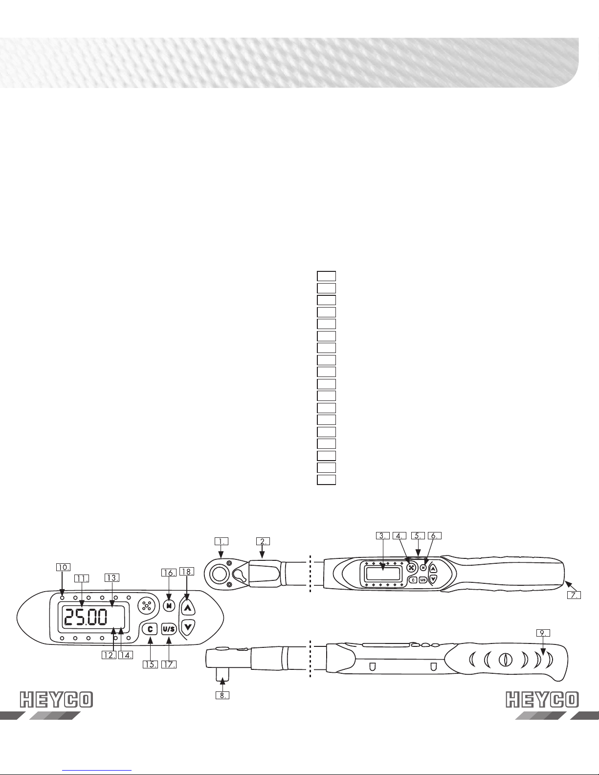
1. InterchangeableHead
2. SensorYoke
3. LCDDisplay
4. Buzzer
5. CommunicationPort
6. Buttons
7. BatteryCap
8. SquareDrive
9. Ergonomic2-Khandle
10. LEDIndicator
11. Torque/AngleValue
12. Pre-settingnumber
13. Unit
14. P(PeakHold)/T(TrackMode)
15. PowerOn/Delete
16. M-Memory
17. Unit/SettingButton
18. Up/DownButton
Names and functions of the parts
N·m
MP
1
Features ....................................3
•Namesandfunctionsoftheparts...............3
•ModelOverview ..........................4
•Specications ............................4
•Note...................................4
Before using the Digital torque wrench........5
•BatteryInstallation .........................5
•Poweronandzeroreset .....................6
•ActivationandStand-by .....................6
•Zeroreset ...............................6
•LowVoltageIndicator .......................7
•Changingthetypeofhead ...................7
Setting, Presets and Operation ................8
•Presettings...............................8
•Unitselection............................10
•SelectTorqueUnit ........................11
•PeakHold/TrackModeSelection.............12
•TrackMode.............................13
•PeakHold .............................14
•PeakHoldModerecordedValueReview ........15
•Anglefunction ...........................16
Communication............................ 16
•Installationofthedriversoftware ..............16
•Transmissionofrecordeddata ................18
Maintenance and Storage .................. 22
•batterymaintenance .......................22
Calibration................................ 23

4 5
Note:
Theaccuracyofreadoutisguaranteedfrom20%to100%of
maximumrange+/-1increment.Theaccuracyoftheindicated
torquevalueisatype-boundsize.Formaintainingaccuracy,
calibratethewrenchinregularintervals.Theintervalsdepend
onthefrequencyofapplications.Generallywerecommendto
calibratethetorquewrenchonceayear.
Model Overview / Specifications
Before using the
Digital torque wrench
Model Art. No. Drive Max. Reach Accuracy
00764000080 764 1/2“ 135 Nm 1 % CW / 2 % CCW
00765000080 765 1/2“ 200 Nm 1 % CW / 2 % CCW
00766000080 766 1/2“ 340 Nm 1 % CW / 2 % CCW
Model Overview
Model Art.No. Drive Max. Reach alarm setting range
(Nm)
Length
(mm)
00764000080 764 1/2“ 135 Nm 6,8 - 135 410
00765000080 765 1/2“ 200 Nm 10 - 200 545
00766000080 766 1/2“ 340 Nm 17 - 340 640
Specifications
All models
measurement accuracy CW +/- 1 % CCW +/- 2 %
data storage locations 50 - 250
communication Yes
pre-settings 9 settings
Operation mode Peak Hold / Track Mode Selection
Units Nm, ft-Ib, in-Ib, kg-cm, Angel°
Head Interchangeable
Bit size 12 (B) x 9 (H)
Axial distance 17,5
teeth 52
Buttons 5
Battery 2 x AA
operating temperature -10°C - 60°C
Storage temperatur - 20°C - 70°C
humidity Up to 90% without condensation
Drop test 1 m
Inserting the batteries
Removethebatterycapwitharotationcounterclockwise.
Insert2AAbatteriesmatchingthe+/-polaritiesofthe
batterytothebatterycompartment.
Replacethebatterycapwithaclockwiserotation.
Battery and cap
+
-

6 7
Power On and Zero reset
of the Torque Wrench
Pressbutton CtoturnontheTorqueWrench.
BeforeusingtheTorquewrench,normallyanauto-reset
willbeprocessedautomatically.
ATTENTION!
MakesurethatnoforcesactingontheTorquewrench
duringthepoweron/resetoperation.Ifyoudidnot
followtheabovementionedpoints,thedisplaywill
showsthefollowingsymbol
Pleaseproceedasdescribedabove.Ifthedisplayshows
ErOafterswitchingon,themaxtorquehasbeen
exceededabout10%Inthiscaseanewcalibrationis
absolutelynecessary.
Activation and Stand-by
TheTorquewrenchwillautomaticallyturnoffafter2min
forpowersaving.Pleasepress CtoturnontheTorque
wrench.
ATTENTION!
Duringthecommunicationperiod,theautopower-off
functionisdisabled.
Reset the Torque wrench
To reset the Torque wrench please press button C.
Should a fault occurs, you could reset the Wrench by
loosen the battery cap, then tight it to re-start. After reset
remember to press C
Activation
Low Voltage Indicator
Ifthebatteryserialvoltageisinlowvoltagestatus,the
DisplaywillshowabatterysymbolandthentheWrench
willturnoff.Pleasereplacebatteries.
Changing the type of the head
Whenusingdifferentinserttoolsthetorquevaluetobeset
duetodifferentdimensions(L1)mustbecalculatedusingthe
followingformula:
D: Thesettorque
D1:Theactualtorqueappliedtothenut.
L1:Thechangedlength
L2:Thestandardlength
L3:Thelengthfromthettingpintothecalibrationpoint
Reference dimensions for all models:
Model Art. No. Drive L2(mm) L3(mm)
00764000080 764 1/2“ 39,5 287,7
00765000080 765 1/2“ 49 381,2
00766000080 766 1/2“ 49 501,2
D=D1* (L3+ L1) / (L3+ L2)
calibrationpoint
L2
L3
x
L1

8 9
Setting, Presets and Operations
Pre-settings
1M-Memory
2Up/DownButton
3Unit/Settings
4Poweron/Delete
TheTorquewrenchcanpreset9targettorquesorangles.
Topresetthevalues,pleasedothefollowingsteps.
1.Throughpressingthebutton Mseveraltimesyouwill
reachtherequestedmemorylocations.
2.Inthememorylocationyoucanselectthepreferedunit
bypressingthebutton
2.Inthememorylocationyoucanselectthepreferedunit
2.Inthememorylocationyoucanselectthepreferedunit
U/S
3.Withtheselectionkeys
>
>
youcanenterthetarget
value
4.Bypressingthebutton Magainyousavethepre-setted
valueandskiptothenextmemorypoint.
Pre- settings
Pre-setting: M2
Pre-setting: M1
25.00
N·m
M
1
T
25.00
N·m
M
2
T
25.00
N·m
M
9
T
Pre-setting: M3
Pre-setting: M9
Press M
Press M

10 11
Setting, Presets and Operations
Unit Selection Set torque
Pre-setting: N·m
25.00
N·m
MT
Press U/S
22 1.2
in·lb
MT
U/S
Unit Selection: in·lb
Unit Selection: ft·lb
18.43
ft·lb
MT
U/S
Unit Selection: kg·cm
255.1
kg·cm
M
1
T
U/S
360°
M
Unit Selection: °(Deg.)
Pre-setting Value
25.00
N·m
>
Press
Increace target Value
30.00
N·m
>
Decrease Target Value
28.00
N·m
1
1
1
1
MT
1
MT
1
MT
1
Press
Press
Press
Press

12 13
Selection of Peak Hold or Track Mode
TheTorquewrenchofferstwodifferenttorquefunctions.
InTrackModeitispossibletotriggerapresettargetvalue.
InthePeakHoldModeyoucanholdorsavetheactually
reachedmeasuredvalue.
Thebothdifferentmodescanbeviewedasfollows:
Note:
1.IfErOappears,itmeansthewrenchhasbeentorquedto
morethan110%ofmaximumtorque.
2. IfyoucreateaTorquevalueof5NmintheTrackModethe
displaywillshowanstartwith5Nm,sowhenyoucreate
lessthan5NmtheDisplaywillshownovaluechanges.The
minimumTorquevalueforthe1/4“+3/8“seriesis3Nm.
3.Whenyoureachthemaximumsettingrangethegreenandred
LEDwillflashtogether.
Track Mode
25.00
N·m
long pressing
Peak Hold-/ Track Mode
e
T
For selection
press
Setting the Peak Hold-/ Track Mode
e
P
Press
Record number
*Note 1
Press
Delete recording
*Note 1
Press
Peak Hold or Track Mode
25.00
N·m
Max. Torque value
*Note 1
START
C
(System initial)
25.00
N·m
*Note 2
Create a torque above 5 Nm
Current torque value
18.00
N·m
Reached 90% of Target Torque
Current torque value
22.50
N·m
Buzzer Green LED
Reached above 90% of setted Torque
((...((... ...))...)) ((...((... ...))...))
Reached the max. target torque
Track Mode
25.00
N·m
*Note 3
Buzzer Red LED
Target Torqe is exceeded
((...((... ...))...)) ((...((... ...))...))
MT
1
MP
1
MT
1
MT
1
MPT
1
MT
1
>
>
U/S
U/S
U/S
U/S

14 15
Peak Hold
Note:
1.IfappearsErO,itmeansthattheWrenchhasbeentorqued
tomorethan110%ofthemaximumtorque.
2.IfappearsFULL,itmeansthewrench‘smemoryisfullandno
morevaluescanberecorded.Pleaserefertothe„PeakHold
ModerecordedValueReview“toclearthememoryrecords.
3.Whenyoureachthemaximumsettingrangethegreenandred
LEDwillflashtogether.
Peak Hold Mode
recorded Value Review
Note:
1.ThePeakHoldrecordedvaluereviewcanalsobeperformedin
themode„monitoring“.
2.Ifyouoperateinthe„PeakHold“mode,thedisplaywillshow
MODE.Pleasegoovertothenextstep.
3.Iftherearenorecords,thedisplaywillshowNONE
4.Thisfunctionisnotsupportedonalltypesofmodels.
5.TheCommunicationmodeisforuploadingrecordeddatatoa
PC.
6.TheCommunicationmodeisalsoforcalibratethetorque
wrench.Pleasecontactyourlocaldealerformoreinformation.
Max. Torque value
*Note 1
START
C
(System initial)
22.50
N·m
Create Torque value
Current Torque
value
18.00
N·m
P
Reached 90% of Target Torque
22.50
N·m
Buzzer Green LED
Reached above 90% of setted Torque
((...((... ...))...)) ((...((... ...))...))
Reached the max. target torque
25.00
N·m
*Note 3
Buzzer Red LED
Target Torqe is exceeded
((((((((( ))))))))) ((((((((( )))))))))
18.00
N·m
P
Released
Create Torque
value flashes
M
*Note 2
ec
Recording
MP
1
MP
1
MP
1
Peak Hold / Track Mode
*Note 1
25.00
N·m
Delete
22.50
N·m
*Note 2
MP
1
MP
1
Setting Peak Hold / Track Mode
long pressing U/S
Press U/S
Record No.
005
Auto
change
*Note 3
18.00
N·m
>
>
Recorded value
Press U/S
Peak Hold /
Track Mode
Delete Record
CL
>
Press
U/S
*Note 4, 5, 6
Communication
Yes
C
C
(Exit)
U/S
No
(Task)
U/S
EL
Deleted
5E
16 17
Angle function
Iftheanglefunctionisnotalreadyselected,youreachthe
anglemodebypressingthebutton
Iftheanglefunctionisnotalreadyselected,youreachthe
Iftheanglefunctionisnotalreadyselected,youreachthe
U/S severaltimes.Inthe
anglefunctionyouhavethepossibilitytosetatargetvalue
asdesired.
Communication
Attention:
BeforetheTorquewrenchwillbeconnectedwiththePC
pleasemakesurethatthesoftwarefromtheenclosedCD
isalreadyinstalledonthePC.
Pleaseusetheprovidedaccessoriestotransmitthedatas
only.
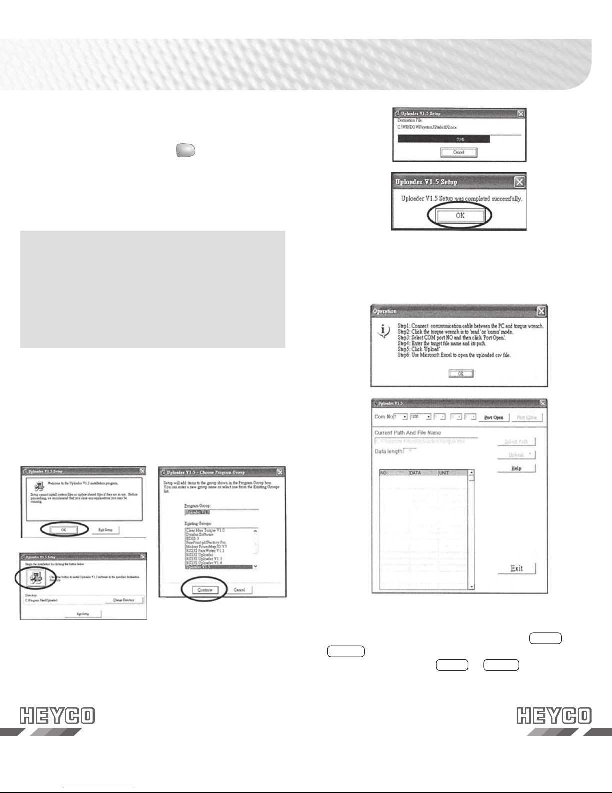
Installation of the driver software
PleaseinserttheinstallationCDintoyourCD-ROMdrive.
Pleaserunthesetup.exe intherootdirectoryoftheCDto
installtheuploader.
Pleasefollowtheinstructionsduringtheinstallation.
Communication
Selctthefollowingle:
Start/Programm/UploaderV1.x/UploaderV1.x
Thenthefollowingwindowsareshown.
ConnectthecommunicationcablebetweenthePCandthe
Torquewrench.ThenpleasechoosethemodeSENDor
COMU.(Pleasereadthesection„Transmissionofrecorded
data“toreachthemodeSENDorCOMU)
18 19
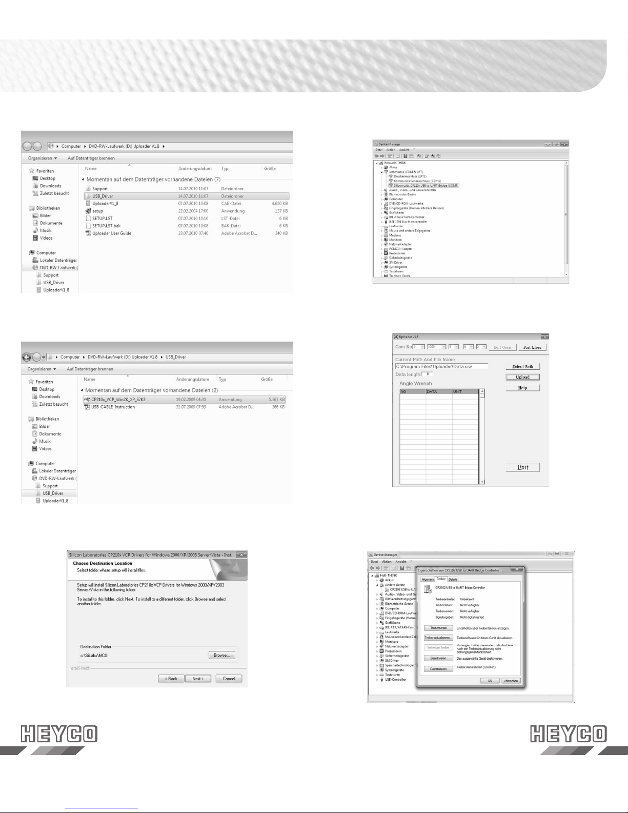
Pleaseopenthele„USB-Driver“
Pleaseexecutethe.exe-le
Pleasefollowtheinstallationinstructions
PleaseselecttherespectiveComPortinthe„Uploader“and
click„Portopen“
PleasecheckthedevicemanagerwhichCOMPortwas
assigned
IftheComPortshouldnotberecognizedautomatically
pleaseclicktwiceontheassigneddevice.
Then,pleasechangeintotheregister„driver“
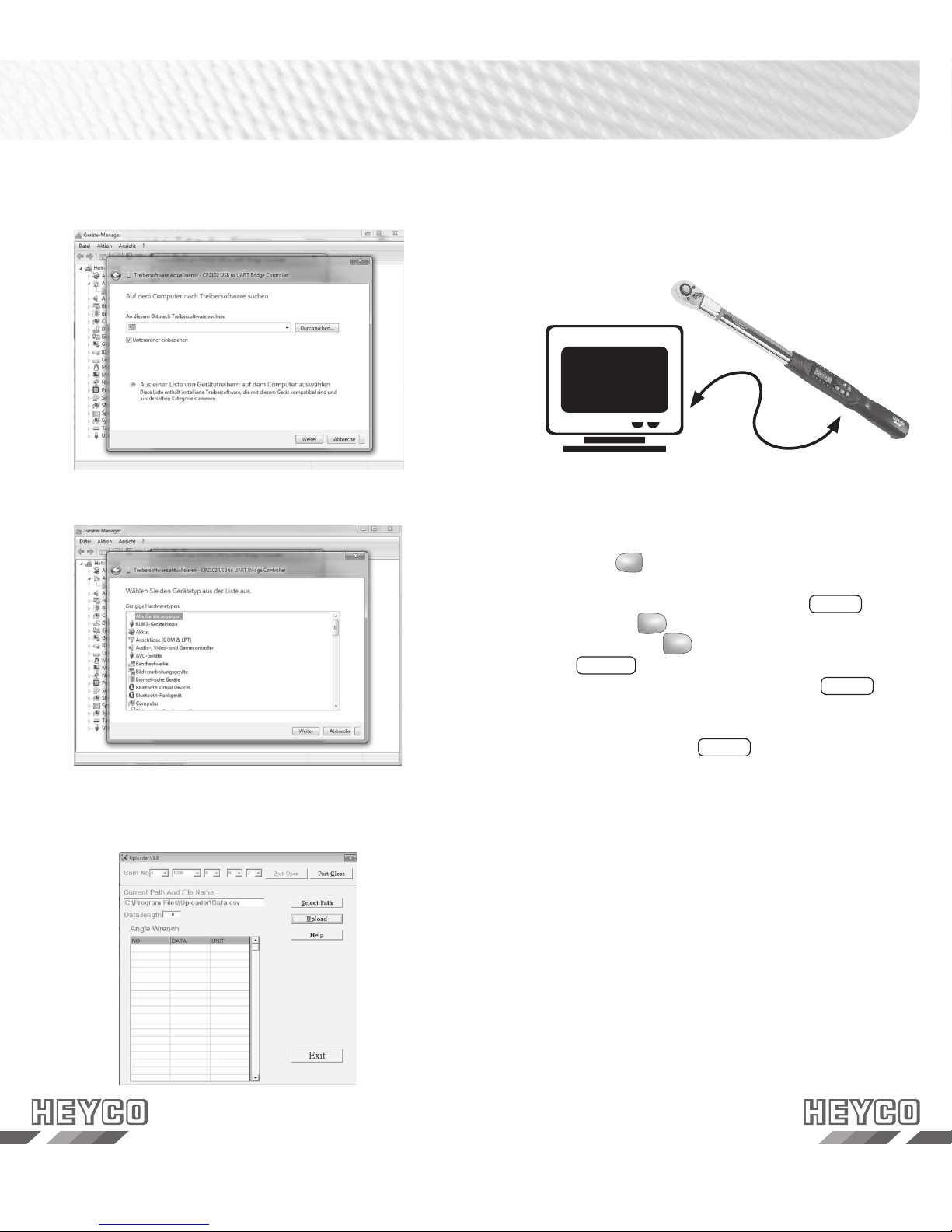
20 21
Pleaseclick„driverstobeselectedfromlist“
PleaseselecttherespectiveComPortinthe
„Uploader“andklick„Portopen“
Pleaseclick„Next“
Connection of the communication cable
TurnofftheTorquewrenchandconnecttheaccessorycable
betweentheCOMPortofthePCandthetorquewrench.
Transmission of recorded data
1.Pleasepress Caftersuccessfullconnectiontoturnon
theTorqueWrench.
2.PleasechangeintotheoperationmodeSENDby
pressingbutton
2.PleasechangeintotheoperationmodeSENDby
2.PleasechangeintotheoperationmodeSENDby
U/S untilyoureachthemenue.By
pressingthebutton
untilyoureachthemenue.By
untilyoureachthemenue.By
U/S severaltimesyoureachthe
modeCOMU.
BypressingthearrowkeysyoureachtheSEND
mode.
3.PleasestarttheuploaderprogramonyourPC.
4.PleaseselectthecorrectCOMportintheuploader
program.
5.Thenpleaseselectthelepathtosavetheuploaded
data.
6.Finally,pressUploadtotransmitthetorquerecordstothe
PC.
7.Theuploadeddatasareshowninacolumnandsavedin
a*.csvle.PleaseuseMicrosoftExceltoview*.csvle.

22 23
Attention!
1. An excessive torque ( 110% of the max.
torque range) can cause damage or loosing
of accuracy.
2. DonotshakeviolentlyordroptheTorquewrench.
3. DonotusethisWrenchasahammer.
4. DonotleavethisWrenchexcessiveheat,humidityor
directsunlight.
5. DonotusethisWrenchinthewater.(notwaterproof)
6. IftheWrenchgetswet,wipeitwithadrytowelas
soonaspossible.Thesaltoftheseawatercandamage
theWrench.
7. Donotuseorganicsolvents,suchasalcoholorpaint
thinnertocleantheWrench.
8. KeeptheWrenchawayfrommagnets.
9. DonotexposethisWrenchtodustorsand.
10.DonotapplyexcessiveforcetotheLCDpanel.
11.Createthetorqueslowlyandcomprisethemiddleof
thehandle.
Battery maintenance
1. Pleaseremovethebatterieswhenyoudidnotusethe
Wrenchoveralongerperiod.
2. Donotmixthebatterytypesorcombineusedbatteries
withnewones.
3. Pleasedisposethebatteriesatanofcialwaste
disposallocation.
CalibrationMaintenance and Storage
Calibration
PleasecalibratetheTorquewrenchinregularintervalsto
savetheaccuracy.Theintervalsdependonthefrequency
ofapplications.Generallywerecommendtocalibratethe
torquewrenchonceayear.
This manual suits for next models
5
Table of contents


