Heyl Testomat Modul TH User manual

1
Testomat®Modul TH
Measuring converter
for residual total hardness
(water hardness)
Operating Instructions

Content
2
Content
Content.................................................................................................2
Important safety information.............................................................4
Intended use .........................................................................................4
Qualification of personnel .....................................................................4
Warnings in this manual........................................................................5
Additional documentation......................................................................5
Special attention is required at this point..............................................5
General Information ..............................................................................5
Requirements for the installation site....................................................5
Requirements of cable for operating voltage and system components
and installed lines .................................................................................6
Requirements for cable ducts...............................................................6
During assembly ...................................................................................7
During operation ...................................................................................7
During cleaning.....................................................................................8
Repairing a defective device.................................................................8
During disposal .....................................................................................8
Operating requirements........................................................................9
Scope of delivery ..............................................................................10
Performance specifications.............................................................10
Interaction with the controller..............................................................10
Available indicators.............................................................................11
Assembly...........................................................................................12
Assembling the Testomat®Modul TH.................................................12
Use of the Testomat®Modul TH within a pressure range of 0.3 to 1
bar.......................................................................................................12
Connecting the water intake and discharge........................................13
Water intake........................................................................................13
Water drain..........................................................................................13
Connect mains and devices................................................................14
Block diagram of Testomat®Modul TH...............................................15
Connecting inputs and outputs ...........................................................16
Internal design Testomat®Modul TH..................................................17
Commissioning.................................................................................18
Inserting the indicator bottle................................................................18
Opening the water inlet.......................................................................18
Venting indicator line...........................................................................19
Functions of the operating and display elements.........................20
Function keys......................................................................................20
Additional control elements on the circuit board.................................20
Display elements of the function keys ................................................21
Adjusting parameters in the device................................................22
Calling up selection mode on the device ............................................22
Starting USB communication..............................................................22
Entering parameters via the Service Monitor program.......................22
Exiting selection mode........................................................................22
Start of measurements........................................................................23
Other functions in selection mode ......................................................23
Functions of the SD card ....................................................................24
Storage of measured values and alarms............................................24

Content
3
Functions of the USB connection........................................................25
The Service Monitor program..........................................................27
Installing the Service Monitor..............................................................27
Selecting language .............................................................................28
Adjusting parameters..........................................................................28
Example: Changing the interval pause in the Service Monitor for
Testomat®Modul TH...........................................................................31
Description of the signal inputs and outputs ................................32
Control input STOP/START................................................................32
Fault signal output “Alarm”..................................................................33
Current output 4-20 mA ......................................................................33
Calculation of output currents.............................................................33
Serial interface....................................................................................34
Notification format...............................................................................34
Error messages and troubleshooting....................................................35
Temporary faults.................................................................................35
Error messages...................................................................................35
Indicator shortage ...............................................................................37
Correct water level in the measuring chamber ...................................38
Maintenance message........................................................................38
Maintenance ......................................................................................39
Cleaning intervals ...............................................................................39
Service instructions.............................................................................39
Cleaning of the measuring chamber and the sight-glass windows.....40
Cleaning the filter housing ..................................................................40
Changing an empty indicator bottle ....................................................41
Replacing an indicator bottle without a shortage notification..............41
Firmware update ...............................................................................42
Firmware update error list...................................................................42
Testomat®Modul TH spare parts and accessories .......................44
Indicators.............................................................................................45
Additional accessories........................................................................45
Optional display for measured value display ......................................45
Technical data...................................................................................46
Conformity Declaration .......................................................................47

Important safety information
4
Important safety information
Read the operating instructions carefully and in full before working
with the device.
Ensure that the operating instructions are accessible at any time for
all users. When an SD card is used in the device, it can also be
stored on the same as a PDF file.
If transferring the Testomat®Modul TH device to third parties, ensure
these operating instructions are always included.
Observe the safety precautions and safety recommendations when
using reagents, chemicals and cleaning agents. Observe the relevant
safety data sheet! For reagents we supply, the relevant safety data
sheets are available online at www.heylanalysis.de.
Intended use
The scope of use of the Testomat®Modul TH is the automatic deter-
mination and monitoring of the residual total hardness (water hard-
ness) in water. In the process, the required measurement scope is
determined based on the selected indicator and corresponding user
programming.
Comply with the output limits specified in the Technical data section
on page 46.
Observe the areas and limits of application of the indicators and the
requirements imposed by the medium to be measured.
The scope of intended use presumes that you have read and under-
stood the instructions and particularly the section Important safety
information.
Improper use is deemed to occur if you use the device
•outside the applicable scope, as specified in these instructions,
•under operating conditions that deviate from the scope specified in
these instructions.
Qualification of personnel
The assembly and commissioning require basic electrical and pro-
cess engineering expertise as well as knowledge of the applicable
specialist terms. The assembly and commissioning must therefore be
performed only by a specialist or a properly trained person instructed
and supervised by a specialist.
A specialist is a person who can draw on professional training,
knowledge and experience as well as knowledge of applicable provi-
sions to assess work assigned to him/her, detect potential hazards
and implement suitable safety measures. A specialist must comply
with the applicable professional rules.

Important safety information
5
Warnings in this manual
These instructions include warnings against specified actions that
involve the risk of injury or property damage. Warnings are structured
as follows:
Description of the type or source of danger
Description of the consequences of non-compliance
Hazard prevention indications. Compliance with these hazard pre-
vention measures is imperative.
The signal word "RISK" refers to a significant danger that represents
a direct threat and will definitely result in severe injuries or even be
fatal if not avoided.
The signal word “WARNING" refers to a possible danger that may
result in severe injuries or even be fatal if not avoided.
The signal word "CAUTION" refers to a potentially dangerous situa-
tion that could result in minor to moderate injuries or property dam-
age if not avoided.
The signal word "NOTE" refers to important pieces of information. If
this information is not heeded, it may adversely affect operational
procedures.
Additional documentation
The Testomat®Modul TH is a system component. Accordingly, you
should also observe the system documentation of the system manu-
facturer.
Special attention is required at this point
General Information
•During assembly and commissioning, observe the specific national
and local requirements.
•Observe the accident prevention and conservation requirements in
the country of use and at the installation site.
•Make no changes or modifications to the device that go beyond the
scope of use specified in these instructions. Doing so will void the
warranty.
Requirements for the installation site
Ensure that the following conditions are met at the installation site:
•Use the device in indoor locations only.
•The ambient temperature is between 10 and 40 °C.
•The installation site is at altitudes under 2000 m.
•The maximum relative humidity is 80 % at temperatures of up to
31 °C (linear declining up to 50 % relative humidity at 40 °C).
SIGNAL WORD!
WARNING
!
CAUTION
!
DANGER
!
NOTE
WARNING
!

Important safety information
6
•The device must always be protected against wetness and mois-
ture. Under no circumstances may it be exposed to splashed water
or condensate.
•Surge category II
•Soiling degree II
Requirements of cable for operating voltage and
system components and installed lines
Use only cables and installed lines which meet the following require-
ments:
•The terminal strips on the circuit board require core cross-sections
of between 0.08 and 2.5 mm2. This applies to single-wire and fine-
wire cores with wire end ferrules without plastic collar.
For fine-wire cores with wire end ferrules and plastic collar, the
cross-section may be up to 1.5 mm2.
For single-wire cores, AWG28 –AWG12 can also be used.
•The cable ducts installed by the manufacturer in the device have a
clamping range of 4.5 to 10 mm. This means that the external di-
ameter of the laid cable must remain within the range of 4.5 to 10
mm. If you use other ducts, the cable diameters must correspond
to the ducts.
Optimum cross-section of the cores
If the core cross-section is less than 0.5 mm2, jamming may occur
when the cores are loosened from the terminal strip. We therefore
recommend using wires with cross-sections greater than 0.5 mm2.
Requirements for cable ducts
•The recesses in the housing are intended for M16 ducts.
•The ducts should have a smooth and rounded opening (to protect
against bending and abrasion).
•The duct should include a strain relief that prevents slippage of the
cable and that cannot be disengaged without a tool.
•You can order cable ducts from us as spare parts (see Testomat®
Modul TH spare parts and accessories on page 44).
NOTE

Important safety information
7
During assembly
•Always disconnect the relevant system component from the power
source before assembling the device or connecting it to the power
supply or disconnecting it from the same. Prevent any inadvertent
reactivation of the device.
•Only connect the device to the operating voltage as specified on
the type plate.
•Observe the technical data and the environmental parameters.
•The connections for operating voltage and relay outputs must be
laid separately from each other, to guarantee corresponding insu-
lation between the cables.
Avoiding interference voltages
The Testomat®Modul TH device requires stable and uninterrupted
supply voltage. Where applicable, use a mains filter to shield the
Testomat®Modul TH device from interference voltages, which may
be generated for example within the network by magnetic valves or
large-scale engines. Never lay the connecting cables in parallel to
mains cables.
Handling may cause damage or destruction of electrical compo-
nents!
If you need to open the upper door, you should take the necessary
safety measures to avoid electrostatic discharge onto the compo-
nents (ESD safety).
Make sure you are earthed before opening the casing.
During operation
•The device has no On/Off switch.
Use an external switch to turn the unit on and off. The switch must
be installed next to the device and must be marked as power
switch for the device - for example with a label.
•Ensure that the maximum electrical load capacity of the switching
outputs is not exceeded, particularly for inductive loads. The power
supply for the user inclusive device is secured with a 1 A fuse,
which means the total of all loads must not reach 1 A.
•In the event of any malfunctions, immediately switch off the Tes-
tomat®Modul TH device and inform the service personnel. Never
attempt to repair the Testomat®Modul TH device yourself. Doing
so will invalidate the guarantee. Repairs must be performed by au-
thorized service personnel only.
WARNING
!
NOTE
ATTENTION
!

Important safety information
8
During cleaning
•Only use a dry and lint-free cloth to clean the device.
•Maintenance and care instructions are included in the section
Maintenance on page 39.
Repairing a defective device
•A defective device, regardless of the guarantee period, can be
serviced only when the device is dismantled and the error is de-
scribed. Also inform us of the indicator type currently in use and
the measured medium. Make no changes or modifications to the
device that go beyond the scope of use specified in these instruc-
tions. Doing so will void the warranty. This applies particularly to
the measuring chamber, the seal of which must remain undam-
aged. If you send the device in for repair, completely empty the
measuring chamber and remove the indicator bottle and the drain
funnel.
Before dismantling, the type of error must be noted (error number,
error effect, log file of the SD card).
•Once a protective device has been triggered (safety fuse), initially
try resolving the cause of error (e.g. by replacing a defective
valve), before reactivating the protective device. Frequent trigger-
ing always signifies an error, which under certain circumstances
may also damage the device.
During disposal
•Dispose of the device in accordance with the regulations of your
country.
Batteries:
The device is built with a removable lithium battery (CR2032 / 3V)
made by VARTA or similar.
Batteries and devices must be disposed of separately! Dispose
of batteries in accordance with the guidelines in your country.

Important safety information
9
Operating requirements
•Wait at least 5 seconds before switching the instrument on and
then off again at the main switch.
•Problem-free operation of the Testomat®device is only possible
when using Heyl Testomat 2000®indicators and only within the pH
range of 4 –10.5! Using external indicators may invalidate the
guarantee.
•Only operate the device within the scope of parameters specified
under section Technical data on page 46.
•For Testomat®devices used to monitor water hardness, large
quantities of heavy metal ions in the hardened water may disturb
the color reaction, particularly
oIron over 0.5 mg/I
oCopper over 0.1 mg/I
oAluminum over 0.1 mg/l (brown-red color indication).
•If the test water contains more than 20 mg/I CO2 (carbonic acid),
erroneous evaluations cannot be ruled out. In this case, use an ir-
rigator (e.g. optional accessory from Gebr. Heyl.).
•The water to be measured must be clean and free of bubbles!
•The concentrations of disruptive ingredients can be determined
with colorimetric TESTOVAL® test comparators from Gebr. Heyl.
•Erroneous evaluations can occur in the event of
oexcessive carbonate hardness
othe presence of disinfecting agents
othe presence of silicate (used to protect pipes). The measur-
ing chamber may become soiled.
•Careful handling of the device enhances the operational safety and
the service life! With this in mind, perform a visual inspection of the
device at regular intervals as follows:
oHas the expiry date of the indicator elapsed?
oAre the hose connections of the dosing pump leakproof?
oIs there any air in the dosing hoses?
oAre all water connections leakproof?
oIs the device excessively soiled?
oAre the measuring chamber and drain channel/drain hose
clean?
•Problem-free operation is contingent on regular maintenance!
Maintenance and care instructions can be found in the Mainte-
nance section on page 39.
•Indications of problems can be found in the Error messages and
troubleshooting section on page 35.
CAUTION
!
NOTE

Scope of delivery
10
Scope of delivery
1x Testomat®Modul TH
1x plastic bag including a screw cap with hole and an insert for the
indicator bottle
1 package with 1 plastic bag with drain funnel
1 User manual
Performance specifications
•The scope of use of the Testomat®Modul TH is the automatic de-
termination of the residual total hardness (water hardness) in wa-
ter. In the process, the required measurement scope is determined
based on the selected indicator and corresponding user program-
ming.
•The device is connected to an overriding control system.
•The output of the measurement values occurs via a 4-20 mA inter-
face and via RS232 interface.
•Analysis trigger:
- Interval mode (the interval pause can be adjusted
from 0-99 minutes)
- External analysis input (start/stop)
- Manual starting
•Shared output for the alarm
Connect to the max. 35 VAC / 60 VDC relay.
•Parameterisation with the Service Monitor program, logging of
error and maintenance messages and a firmware update with the
SD card
•USB connection for service purposes and for parameterisation
with the Service Monitor program
•History for error and maintenance messages
•Free selection of hardness units in °dH, °f, ppm CaCO3, or mmol/l
•Highly accurate measurement thanks to the use of precise pis-
ton-dosing pump
•Built-in self-test with ongoing monitoring
•Extended operating periods due to a 500 ml reagent stock
Interaction with the controller
When using the 4-20 mA interface, the Testomat®Modul TH sends its
determined measurement result as a current value to the controller,
which determines the measurement value from the current, e.g. in
°dH.
CAUTION
!
11
The reagents used determine the device’s measurement range.
To calculate the measurement value, the controller requires the
measurement range final value for the indicator model used. This is
assigned to the 20.0 mA current.
When using the RS232 interface, the Testomat®Modul TH transfers
its determined measurement result to the control system. All meas-
urement data and error messages are always transferred to the
RS232 interface, even if they are not used.
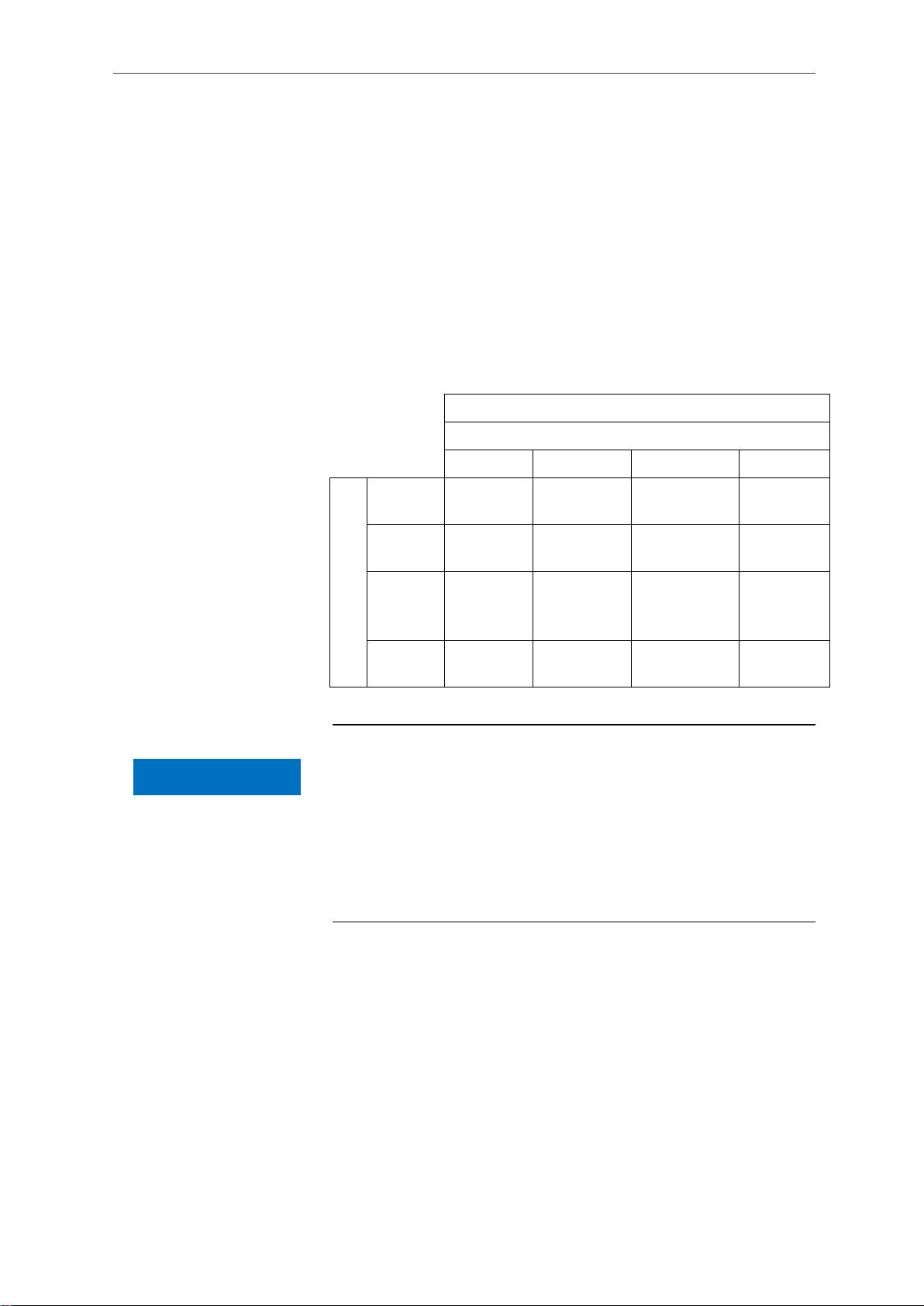
Available indicators
Parameter/indicator type
Water hardness
TH 2005
TH 2025
TH 2100
TH 2250
Unit
°dH
(resolution)
0.05 - 0.50
(0.01)
0.25 - 2.50
(0.05)
1.0 - 10.0
(0.2)
2.5 - 25.0
(0.5)
°f
(resolution)
0.09 - 0.89
(0.02)
0.45 - 4.48
(0.1)
1.8 - 17.9
(0.4)
4.5 - 44.8
(1.0)
[ppm]
CaCO3
(resolution)
0.89 - 8.93
(0.2)
4.5 - 44.8
(0.9)
18 - 179
(3.8)
45 - 448
(10)
mmol/l
(resolution)
0.01 - 0.09
(0.01)
0.04 - 0.45
(0.01)
0.18 - 1.79
(0.04)
0.45 - 4.48
(0.1)
Be careful to ensure that Heyl indicators are used!
Using external indicators may result in considerable measurement
deviations or measurement errors. Damage caused by foreign parti-
cles in the area of the dosing pump, measuring chamber or valves is
also possible. This may invalidate the guarantee!
At Heyl, we always strive to ensure the consistently high quality of
our indicators. They are specially tailored to the requirements of our
measuring devices and guarantee flawless measurement results.
NOTE

Assembly
12
Assembly
Hazard due to defective assembly!
Assemble the Testomat®Modul TH device in a location shielded
from drips and splashes of water, dust and aggressive substances
–e.g. in a switching cabinet or on a suitable wall.
Notes for problem-free operating procedures
Assemble the Testomat®Modul TH device vertically and without
mechanical stresses.
Assemble the Testomat®Modul TH device in a location free of
vibration.
Assembling the Testomat®Modul TH
Requirements for the installation site
We recommend short intake lines (under 3 m) to the Testomat®Mod-
ul TH. For intake lines longer than 3 m, purge periods of longer than
60 s must be configured (see section Internal “Flush time” on page
29).
Drill the mounting holes as specified in the accompanying sketch-
es.
Secure the device with three screws in a suitable place in the
switching cabinet or on the wall.
Use of the Testomat®Modul TH within a pres-
sure range of 0.3 to 1 bar
Before assembling please check whether adaptation to a lower work-
ing pressure is required. When delivered, the device is equipped for a
pressure range of 1 to 8 bar. To operate the device within a pressure
range of 0.3 to 1 bar, the flow controller valve body should be re-
moved (e.g. when using a type R mini irrigator, see section Additional
accessories on page 45). For this purpose, take the locking pin
from the controller/filter housing . Then pull the controller plug
on the metal brackets out of the drill hole. Then remove the flow con-
troller valve body and re-insert the controller plug and locking pin.
At pressures under 0.3 bar or when sucking out of a tank, our Me-
puClip booster pump can be used (see section Additional accesso-
ries on page 45).
NOTE
NOTE
Remove the
flow controller
valve body for a
pressure range
of 0.3 to 1 bar
CAUTION
!
Assembly
13
Connecting the water intake and discharge
When using a cooler
Water exceeding 40 °C may lead to burns and may damage the
parts of the Testomat®Modul TH exposed to the water.
Notes for problem-free operating procedures
The water pressure must be within the range 0.3 to 8 bar.
To operate within a pressure range of 0.3 to 1 bar or when supply-
ing via a booster pump, please remove the controller valve body
from the controller and filter housing. The pump should have a ca-
pacity of 25 to 35 liters/hour and be correspondingly resistant to
the medium being measured (e.g. our booster pump MepuClip Art.
No. 270410).
For operation exceeding 8 bar, a pressure reducer must be used.
Significant pressure fluctuations should be avoided.
The measurement water temperature must be between 10 and
40 °C.
For water temperatures exceeding 40 °C, a cooler must be in-
stalled in the intake of the Testomat®Modul TH.
Water intake
The test water is extracted from the sampling pipe and channelled to
the supply nozzles of the Testomat®Modul TH. The device comes
with a plug connection for plastic hoses 6/4 x 1 as standard (external
diameter 6 mm / internal diameter 4 mm, wall thickness 1 mm).
Connect the linking piece for the water intake of the Testomat®
Modul TH directly to the sampling pipe directly behind the water
treatment plant.
Always establish the connection vertically upwards, to prevent dirt
particles from being conveyed from the sampling pipe to the de-
vice.
Assemble a manual stop valve in the water intake to the
Testomat®Modul TH.
For the water intake use opaque plastic pressure hose 6/4 x 1
(max. length 5 m).
Purge the water intake to remove dirt particles.
Water drain
The water is conveyed through the measuring chamber via an open
funnel and the drain hose installed on the same and into the
duct.
Remove the supplied funnel.
NOTE
CAUTION
!

Assembly
14
Accommodate the funnel underneath, in the recess of the hous-
ing designated for that purpose.
Connect the funnel of the Testomat®Modul TH with a drain hose
(internal diameter 12 mm).
Lay this hose free of back pressure and without the siphon
effect to the drain .
Connect mains and devices
Connect the device only to a 24 VDC power supply.
Risk of injury from assembly when voltage is present!
Unless you disconnect the power supply before commencing assem-
bly, you risk injury, destruction of the product or damage to system
components.
Disconnect all power to the relevant system component before
assembling the Testomat®Modul TH device.
When connecting, use only verified cables with sufficient line
cross-section (see Requirements of cable for operating voltage
and system components and installed lines on page 6).
Danger of damage due to electromagnetic fields!
If you assemble the Testomat®Modul TH device or connecting cables
parallel to mains cables or in the vicinity of strong electromagnetic
fields, the device may be damaged or the measurement disrupted.
Keep the connecting cables as short as possible.
Lay the connecting cables and mains cables separately.
Shield the device from strong electromagnetic fields.
WARNING
!
CAUTION
!

Assembly
15
Block diagram of Testomat®Modul TH
Illustrated position of relays: Device without current

Assembly
16
RS232
Connecting inputs and outputs
Correct connection of the inputs and outputs
Incorrect connections will damage the device!
Do not expose the connections to any external voltage!
Ensure that the cores in the terminals are securely in place.
A detailed description is included in section Description of the signal
inputs and outputs on page 32.
Terminal
designation
Type
Function
Note
OUT +
OUT -
OUT
Current loop 4 - 20 mA
Galvanically isolated
START
GND
IN
External start/stop of analysis
Ground
Only connect isolated
break contacts/closing
contacts!
GND
IN
Ground
RxD
TxD
IN
OUT
RS232 interface
Not galvanically isolat-
ed (RxD currently not in
use)
Terminal
designation
Type
Function
+ / -
Operating voltage
24 VDC
NO
Alarm output –NO contact
floating relay output/
max. 35 VAC/60 VDC
C
Alarm output –Root
floating relay output/
max. 35 VAC/60 VDC
NC
Alarm output –NC contact
floating relay output/
max. 35 VAC/60 VDC
CAUTION
!

Assembly
17
Internal design Testomat®Modul TH
Control circuit board,
Base circuit board with terminal strips for inputs and outputs is behind
it
Cable gland on both sides
Dosing pump
Optical unit (transmitter right/receiver left)
Solenoid valve
Water connections, inlet and outlet
Controller / Filter receiver
Measuring chamber
Commissioning
18
Commissioning
Flawless operation of the Testomat®Modul TH device is only
guaranteed when Heyl indicators are used! The use of external
indicators may invalidate the guarantee.
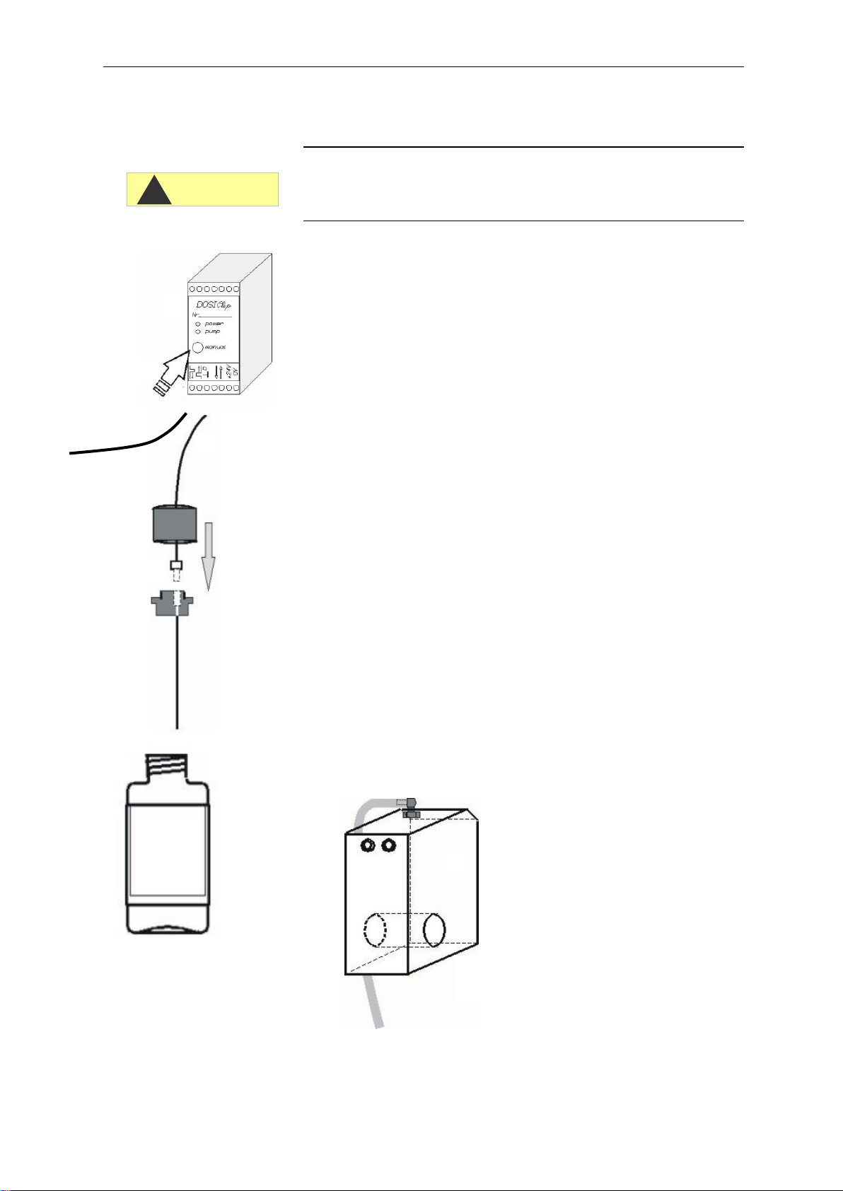
Inserting the indicator bottle
Remove the cover of the Testomat®Modul TH. To do this, raise
the cover slightly and push it forward to remove it.
Remove the cap from the indicator bottle.
Remove the plastic bag from inside the lower housing door. The
plastic bag contains the screw cap with hole and the insert
for the screw cap.
Connect the parts as shown on the left:
Screw the hose connector of the intake hose hand-tight into
the insert .
Place the insert with the screwed-in intake hose into the indicator
bottle .
Now screw the screw cap with hole hand-tight onto the indicator
bottle.
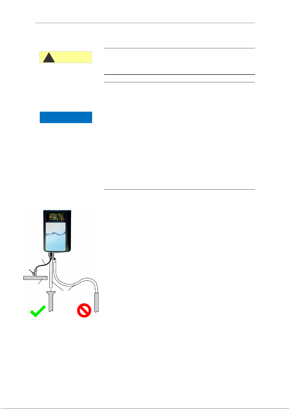
Opening the water inlet
Slowly open the manually operated shut-off valve to prevent the
measuring chamber from overflowing. The flow controller re-
quires a few seconds to function correctly.
Make sure that the water conducting parts are not leaky.
If water sprays from the tube of the measuring chamber ,
reduce the amount of inlet water via manually operated shut-off
valve. It should take 2 to 6 seconds to fill the measuring chamber!
CAUTION
!
Indicator
Measuring chamber
with tube

19
Venting indicator line
The pump (DOSIClip) automatically primes the indicator in opera-
tion.
The pump’s suction hose and transport hose must be filled with
the indicator up to the measuring chamber so indicator is present for
initial analyses.
To do this, press the “Manual” button on the DOSIClip pump sev-
eral times until the suction and transport hose are filled with indica-
tor up to the measuring chamber.
In the event of a build up of bubbles, turn the suction and transport
hose’s hose connector a bit tighter by hand if required.
Press the Manual function key on the control circuit board to quit
standby mode.
The device starts the analysis.

Functions of the operating and display elements
20
Mini
USB
Internal
interface
BOOT
Slot
optional display
Functions of the operating and dis-
play elements
Function keys
The Manual function key is used to start the standby mode which
prevents the intermittent start of an analysis. The yellow LED flashes
above the key in the process. After pressing the key again, the
standby mode is cancelled again, and an analysis starts. During an
analysis, the key flashes.
Acknowledge error and maintenance messages with the Alarm func-
tion key. An alarm message (key lights up red) is acknowledged
when the error has been corrected. The key’s light goes out. A
maintenance message (the LED above the key lights up yellow) is
acknowledged when the maintenance work has been performed.
You can set the indicator stock to 100% with the 100% function key
(see section Changing an empty indicator bottle on page 41).
Additional control elements on the circuit board
•RESET key: To reset the controller, proceed as for switching on
and off.
•BOOT key: Used for firmware update and selection mode.
•Plug-in slot for SD card: For parameterisation, errors and
maintenance messages and firmware updates
•USB socket: For connecting a computer to the Service Monitor for
parameterisation.
•Battery holder: The battery holder houses a CR2032 lithium bat-
tery to retain the time setting even if the device is switched off.
Manual
100%
Alarm
RESET
Battery holder
Mini
USB
Slot for
SD card
Other manuals for Testomat Modul TH
1
Table of contents


