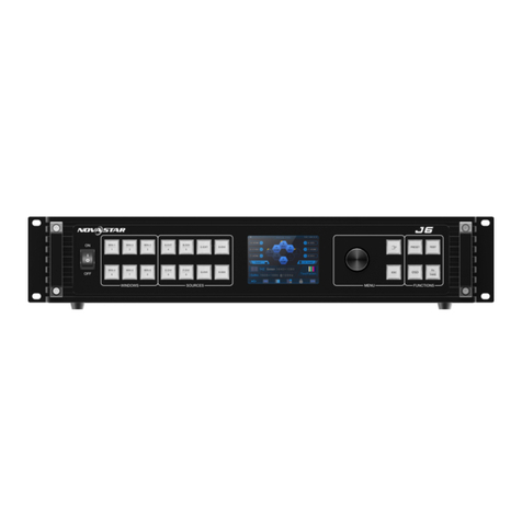
NovaStar J6 User manual

J6 User Manual
User Manual
Multi-Screen Splicing Processor J6
Rev1.0.1
NS160110162
Xi’an NovaStar Tech Co., Ltd.

Statement
Dear users,
You are welcome to use the J6, a multi-screen splicing processor of Xi'an NovaStar
Tech Co., Ltd. (hereinafter referred to as NovaStar).
This document is intended to help you understand and use the product. For accuracy
and reliability, NovaStar may make improvements and/or changes to this document at
any time and without notice.Any problem in use or any good suggestion, please
contact us through ways provided in the document. We will do our utmost to solve the
problems and adopt the suggestions after evaluation as soon as possible.
Copyright © 2018 NovaStar
All rights reserved. No part of this document may be copied, reproduced, extracted or
transmitted in any form or by any means without the prior written consent of Xi’an
NovaStar Tech Co., Ltd.
Trademarks
is a trademark of NovaStar.
Xi’an NovaStar Tech Co., Ltd.

Contents
1 Overview........................................................................................................................... 2
1.1 System Architecture....................................................................................................................................... 2
1.2 Software Installation ...................................................................................................................................... 2
2 Appearance...................................................................................................................... 3
2.1 Front Panel .................................................................................................................................................... 3
2.2 Rear Panel..................................................................................................................................................... 4
3 Signal Connection........................................................................................................... 6
4 Menu Operations ............................................................................................................. 7
4.1 Output Settings.............................................................................................................................................. 9
4.2 Window Settings............................................................................................................................................ 9
4.3 Preset Recall ............................................................................................................................................... 10
4.4 Input Settings............................................................................................................................................... 10
4.5 Display Control .............................................................................................................................................11
4.6 Advanced Settings........................................................................................................................................11
4.7 Communication Settings.............................................................................................................................. 12
4.8 Language Settings....................................................................................................................................... 12
5 System Mode ..................................................................................................................13
5.1 Switcher....................................................................................................................................................... 13
5.2 Splicer.......................................................................................................................................................... 15
6 Electrical Parameters.....................................................................................................17
7 Installation Dimensions .................................................................................................19
8 Troubleshooting .............................................................................................................20
Xi’an NovaStar Tech Co., Ltd.

www.novastar.tech 1
Safety Notice
To avoid potential hazards, please use this product according to regulations. In the
event of breakdowns, non-professionals are not allowed to disassemble it for
maintenance without permission. Please contact the after-sales department of
NovaStar timely.
High voltage danger: The operating voltage range of this product is 100V to 240V AC.
Grounding: This product is grounded through the grounding cord of power supply. Please
keep the grounding conductor well grounded.
Electromagnetic interference: Keep this product far away from magnets, motors and
transformers.
Moisture proof: Keep this product in a dry and clean environment. In case of liquid
immersion, please pull the power plug out immediately.
Keep the product away from flammable and explosive hazardous substances.
Prevent liquids or metal fragments from dropping into the product in order to avoid safety
accidents.
Change History
Date
Version
Description
Remarks
2017-04-18
V1.0.0
First release
Glossary of Terms
Preview: Preview includes input preview and preview in switcher mode.
OSD: On Screen Display. Preloaded images or texts can be overlapped and displayed
on the any area of the screen.
Genlock: Synchronization lock, enabling one system or multiple systems in sync with
the same video source.
Vertical synchronization: The accuracy level of synchronization.
Cascade: Connect multiple J6 units in specific order so as to output images with larger
resolution.
Note: Terms explained here are only for the chapters below. We will be sorry if these
terms cannot help you.
Xi’an NovaStar Tech Co., Ltd.

www.novastar.tech 2
1 Overview
Developed by NovaStar, J6 is a high-performance multi-screen splicing processor
featuring powerful image processing. Multiple video inputs can be overlapped and
displayed on a display system composed by 4 screens after each of the input is scaled.
J6 supports a wide range of inputs which can be spliced into a bigger picture.
Based on a powerful FPGAprocessing platform, J6 supports quick seamless switch
between input sources and supports transition effects such as fade, etc., allow you to
experience more flexible screen layouts.
In addition, J6 can work with V-Can, a new smart management software, to enable
more screen splicing effects and better satisfy your needs.
1.1 System Architecture
1.2 Software Installation
Just like the installation of other common software, install V-Can following the setup
wizard.
In case of antivirus or firewall popups during installation, please
permit them because serial driver may need to be installed during
program installation.
视频源输入 J6 控制器 显示屏
Xi’an NovaStar Tech Co., Ltd.

www.novastar.tech 3
2 Appearance
2.1 Front Panel
①
Power switch
ON/OFF
②
Window buttons
WIN1-WIN6, press a button to enter the relevant menu of window properties
for quick settings.
A window is opened when its button indicator is on.
A window is closed when its button indicator is off.
Hold down the window button to close the window on the home screen.
③
Input source buttons
Status of signal sources
A signal source is accessed but not in use when the signal indicator is on.
A signal source is accessed and in use when the signal indicator becomes
brighter.
A signal is not accessed when the signal indicator is off.
④
LCD panel
Used for displaying current status and menus of the processor.
⑤
Knob
Rotate the knob to select menus or adjust parameters
Press the knob to enter main menu or confirm current selection.
⑥
ESC button
Exit from current operation or option.
⑦
Navigation button
Hold down the button to enter the quick navigation screen and quickly learn
how to use J6.
Xi’an NovaStar Tech Co., Ltd.

www.novastar.tech 4
⑧
Function buttons
PRESET: Press the button to enter the “Preset Recall”menu. 16 presets
are available for users to use, save, delete, etc.
TEST: Hold down the button to enter the test pattern settings menu.
OSD: Switch for loading images or texts. Prestored images or texts can be
overlapped and displayed.
Fn (TAKE):A user-definable function button
−Fn (TAKE) button can be set as “Screen Settings”, “Window Settings”,
“Black Out” or “Freeze” when the “System Mode” is set to “Splicer”.
−Fn (TAKE) button can be set as “Take” or “Switch”when the “System
Mode” is set to “Switcher”.
Tip:
Additional description for PRESET: Users can rename the presets through the control
software V-Can.
2.2 Rear Panel
Inputs
Input-A
Can be changed to interface of HDMI1.4, DP1.1 or DualLink DVI as
required.
Input-B
SDI
SDI Loop, SDI loop output
Input-C
Can be changed to DVI/HDMI/VGA depending on the requirements of users
to allow input of different video sources.
Input-D
DVI1
Input-E
DVI2
Input-F
DVI3
Input-G
DVI4
Input-H
SDI
SDI Loop, SDI loop output
Outputs
Xi’an NovaStar Tech Co., Ltd.

www.novastar.tech 5
HDMI preview
HDMI output, capable of previewing the PVW, PGM and 8 input sources.
DVI1-DL/PGM1
DVI1 output
This interface works as PGM1 output when system mode is switcher, and as
DualLink out1 when output mode is set to DualLink.
DVI2/PGM2
DVI2 output
This interface works as PGM2 output when system mode is switcher, and is
invalid when output mode is set to DualLink.
DVI3-DL/PVW1
DVI3 output
This interface works as PVW1 output when system mode is switcher, and as
DualLink out2 when output mode is set to DualLink.
DVI4/PVW2
DVI4 output
This interface works as PVW2 output when system mode is switcher, and is
invalid when output mode is set to DualLink.
Control
ETHERNET (RJ45)
Control interface
USB (Type-B)
USB control interface for connecting upper computer
USB (Type-A)
For cascading multiple J6 units
Genlock IN-Loop
For connecting synchronous signals and for synchronous cascade of J6
units.
Power
AC 100-240V, 50/60HZ
AC power interface
Xi’an NovaStar Tech Co., Ltd.

www.novastar.tech 6
3 Signal Connection
Please refer to the interface introduction in previous chapter to connect hardware
devices (Please turn the power off before connecting signals).
J6-Splicer
Computer Camera
Power Input
Genlock Source
Computer Computer
Camera
LED Display
J6-Switcher
Computer
Camera
Power Input
Genlock
Source
Computer Computer
Camera
Monitor
LED Display
Monitor
Xi’an NovaStar Tech Co., Ltd.

www.novastar.tech 7
4 Menu Operations
After startup, the home screen on the LCD panel is shown as below:
A
/ /
Pure color: The signal source is in use and signals are available.
Semitransparent: The signal source is not in use and signals are
available.
Transparent: The signal source is not in use and no signal is available.
B
Transparent: The window has input signal and the type of the signal
source is displayed in the window.
Semitransparent: The window has no input signal. The window will
display the input source used to open a window last time, or the default
input source. When opening a window using the window template, the
window will use the source of the INPUT-C connector as the default
source.
C
Current preset is displayed. Pure color indicates the preset is turned on
and semitransparent indicates the preset is not turned on.
Xi’an NovaStar Tech Co., Ltd.

www.novastar.tech 8
D
Next preset and its turn-on time are displayed. Pure color indicates the
schedule of the preset is displayed and transparent indicates the
schedule is not displayed and showing “N/A”.
E
/ / /
/ / /
Screen structure and size, screen structure supports:
1×1, 1×2, 1×3, 1×4, 2×1, 2×2, 3×1, 4×1.
Output resolution
Maximum supported resolution: 3840×1080@60Hz.
Prompt for test pattern, freeze, black out, etc.
No icon is shown when the unit works normally.
F
/ /
Device connection status: Not connected/Connected to
network/Connected to USB
/
OSD on/OSD off
/
Transition effects: 21 effects, such as cut and fade
/
Working mode: splicer/switcher
/
Button unlocked/button locked
Hold down the knob and ESC button simultaneously to lock or unlock
the buttons. All the buttons on the panel are not available after they are
locked.
/ / /
Genlock is turned off. /The reference source of Genlock is lost or
abnormal. /Genlock is locked. /Genlock is to be locked.
In the home screen, press the knob to enter main menu (Press the knob to enter
sub-menus and press ESC to return to the previous menu. Rotate the knob clockwise
to move down and rotate anticlockwise to move up.).
Main menu is shown as the figure below. The main menu includes: “Screen Settings”,
“Window Settings”, “Preset Recall”, “Input Settings”, “Display Control”, “MVR Selection”,
“Advanced Settings”, “Communication Settings”and “Language”.
Xi’an NovaStar Tech Co., Ltd.

www.novastar.tech 9
Figure 4-1 J6 menu tree
4.1 Output Settings
As shown in the figure below, set the mosaic mode of output images in the “Output
Settings”menu. Set the resolution of output images in “Output Resolution”. Preset
resolution and custom resolution are optional. Set the Width and Height of current
screen in the “DVI Output”menu.
4.2 Window Settings
This processor is capable of displaying 6 windows at most and the input source, size,
position, priority, input crop, border parameters, etc. of each window are settable.
Priority: allows to set the display priority of current window.
Input Crop: allows to turn on “Input Crop” and display cropped content on LED screen.
Border Settings: allows to add or delete borders and set border width and height as
well as border color.
Xi’an NovaStar Tech Co., Ltd.

www.novastar.tech 10
4.3 Preset Recall
Switch presets.Apply the preset parameters directly. 16 presets in total are available
for users to set and use.
Preset Recall
J6 supports 16 user presets.After the preset data is configured, uses can directly use
the configured presets by their names.
Rotate the knob to select a preset you want to load and press the knob to load it.
When you enter the Preset Recall menu, the indicators of number buttons on the
front panel will turn on. You can press the number button to quickly load the
corresponding preset. If the preset No. is a double-digit value, press the two
numbers quickly within 2 seconds. For example, to load Preset 15, press 1and 5
quickly within 2 seconds.
Preset Templates J6 provides 6 preset templates. Users can use the templates to quickly open
windows to fill the whole screen loaded by J6.
Provided preset templates are 1×1, 1×2, 2×1, 1×3, 2×2 and 1×4.
4.4 Input Settings
Input resolution of signal sources, including DVI, HDMI and DP, can be set. Preset
resolutions and custom resolutions are available for users.
Preset resolutions include 800×600, 1024×768, 1280×720, 1280×768, 1280×800,
1280×1024, 1366×768, 1440×900, 1600×1200, 1680×1050, 1920×1080, 1920×1200,
2048×640, 2048×1152, 2048×1536, 2304×1152, 2560×816, 2560×960, 2560×1600
and 3840×1080.
Preset refresh rates include 50 Hz, 60 Hz, 75 Hz and 120 Hz.
Custom resolution includes custom width, custom height and custom refresh rate.
Xi’an NovaStar Tech Co., Ltd.

www.novastar.tech 11
Note:
Select “Apply”and confirm the selection after the settings are done, and then the
settings will take effect.
The total number of pixels is not greater than 2.1 million. The width of custom
resolution cannot be greater than 3840 and height not greater than 1080.
4.5 Display Control
As shown in the figure below, “OSD” can be turned on/off, and “Transition Effect”
(including fade and cut), “Switching Time”, display state and image quality can be set in
the “Display Control” menu.
Input Color Settings: Select an input source to be adjusted to adjust its brightness,
contrast, saturation, hue or reset to defaults.
Tip:
OSD function description: You can turn on/off OSD. Control software is required
for adding and setting detailed contents.
Transition effect description: Switching time setting can change the transition time
of an effect.
4.6 MVR Selection
Users can scale up a specific input source, the PVW or PGM to view on the preview
monitor.
On the MVR selection menu, rotate the knob to select an input source, the PVW or
PGM and press the knob to display the selected target on the monitor in full screen.
When you press the knob again, the current scaled display will exit.
4.7 Advanced Settings
System modes include: “Splicer”and “Switcher”.
Output modes include: “SingleLink”and “DualLink”.
In synchronous mode, any one of the input sources can serve as synchronous source.
Following synchronous sources are selectable: GenLock and any one of the input
sources.
Xi’an NovaStar Tech Co., Ltd.

www.novastar.tech 12
4.8 Communication Settings
Communication modes include: “USB preferred” and “LAN preferred”.
“Network”: allows to set IPv4 Config (manual and auto), IP address, and subnet mask
or to reset to default network parameters.
Tip:
This processor supports two control modes: USB and Ethernet cable. Please
select according to actual needs.
IP and subnet mask can be edited only when network mode is set to “Manual”.
4.9 Language Settings
J6 currently supports “Chinese” and “English” only. Users can switch languages as
required.
Xi’an NovaStar Tech Co., Ltd.

www.novastar.tech 13
5 System Mode
System modes include “Splicer” and “Switcher”. In these two modes, J6 can work with
the software V-Can.
5.1 Switcher
Step 1: Refer to the hardware connection diagram to connect hardware devices.
Step 2: Start V-Can, connect devices and adjust their parameters. Set system mode to
“Switcher”.
Step 3:Add windows in editing area and set window parameters. Then output the
edited content to LED screen.
“PVW” area is for editing. Different signal sources can be selected. Windows can be
added and window parameters can be edited. Six windows can be added at most.
Splicing area supports up to 1×2 layout (Splicing mode can be chosen without
limitation). Windows can be overlapped. The overlapped area displays the content of
the window with higher priority.After the content is edited, result can be previewed on
the monitor and can be adjusted.
The display parameters set before can be saved as preset, which is convenient for
using next time.
Xi’an NovaStar Tech Co., Ltd.

www.novastar.tech 14
As shown in the figure below, content in “PGM” area is being displayed on the LED
screen.After the content to be output is edited in the “PVW” area, click the “TAKE”
button in the top right corner of the page and then the content in “PVW” area will be
mapped to “PGM” area. LED screen will display the edited content.
Xi’an NovaStar Tech Co., Ltd.

www.novastar.tech 15
5.2 Splicer
Step 1: Refer to the hardware connection diagram to connect hardware devices.
Step 2: Start V-Can, connect devices and adjust their parameters. Set system mode to
“Splicer”.
Step 3:Add windows in editing area and set window parameters. Then the edited
content is displayed on LED screen in real-time.
Splicing area supports up to 2×2 layout. (Splicing mode can be chosen without
limitation).
Different signal sources can be chosen. Windows (six at most) can be added. Window
parameters can be edited. Windows can be overlapped. The overlapped area displays
the content of the window with higher priority.
The display parameters set before can be saved as preset, which is convenient for
using next time.
Xi’an NovaStar Tech Co., Ltd.

www.novastar.tech 16
Xi’an NovaStar Tech Co., Ltd.

www.novastar.tech 17
6 Electrical Parameters
Inputs
Port
Qty
Resolution Specifications
DualLink DVI/HDMI1.4/DP1.1
(Choose one from these inputs)
1
4K×2K@30Hz
2560×1600@60Hz (downward compatible)
DVI (DVI-D)
4
VESA standard
1920×1080@60Hz (downward compatible)
CVBS(BNC)/VGA (DB25)/HDMI/
DVI (DVI-D)
(Choose one from these inputs)
1
VESA standard
1920×1080@60Hz (downward compatible)
SDI(BNC)
2
720p, 1080p
Outputs
Port
Qty
Resolution Specifications
DVI (DVI-D)
4 groups
(8 channels)
Resolution is programmable output. The maximum supported
resolution of each port is 1080p (DualLink output is available for
DVI1 and DVI3.)
SDI Loop (BNC)
2
480i, 576i, 720p, 1080i/p(3G SDI), same as SDI input
HDMI (Type A)
1
Supported output resolution: 1920×1080@60Hz
Control
Port
Qty
Description
ETHERNET
1
Control port
Xi’an NovaStar Tech Co., Ltd.
Other manuals for J6
3
Table of contents
Other NovaStar Media Converter manuals
