HR16, 16-Channel Video Encoder
QUICK INSTALLATION GUIDE
i3 INTERNATIONAL INC. 1.866.840.0004
www.i3international.com
U.S.A 4450 Witmer Industrial Estates Unit 4
Niagara Falls, NY 14305
Canada 780 Birchmount Road, Unit 16,
Scarborough, ON, M1K 5H4
ADDING HR16 INPUTS TO i3 SRX-PRO SERVER 22. Save the settings. Your HR16 encoder is now connected to SRX-Pro Server
and is ready to record. You may change resolution and frame rate for the
Main stream of each of the video inputs connected to HR16 in the IP Camera
tab menu.
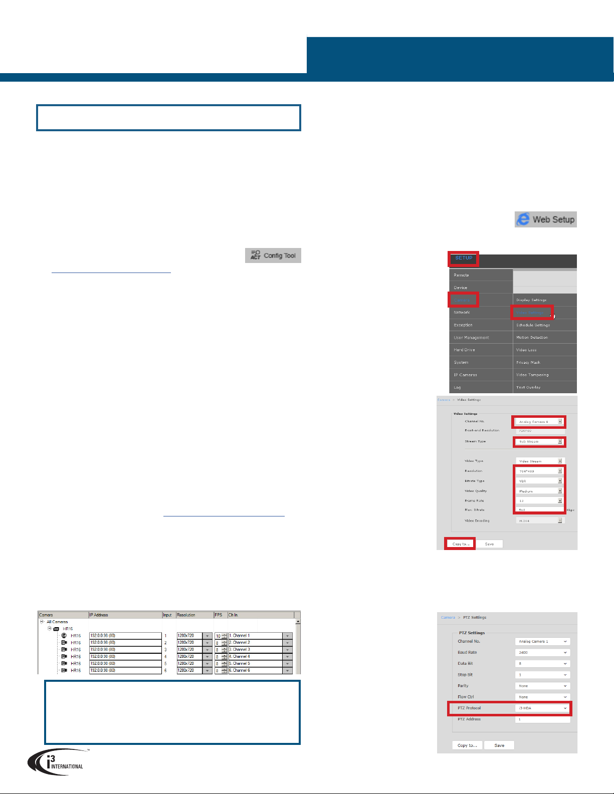
ADJUSTING FRAME RATE AND RESOLUTION FOR INPUT
SUB-STREAMS.
Each analog video input connected to HR16 has two congurable streams:
Main Stream and Sub Stream. While some settings for the input’s Main Stream
(FPS and resolution) can be adjusted directly from SRX-Pro Server’s IP Camera
tab, the Sub Stream settings can only be adjusted through the HR16 browser
interface.
1. Go to Setup > IP Camera setup tab in SRX-Pro Server.
2. Select your HR16 encoder in the list and click the Web Setup button.
3. In the IE Browser window, enter HR16 login and password: i3admin /
i3admin.
4. Go to Setup > Camera > Video
Settings.
5. In the Video Settings setup, select
your Channel No. (video input
number that corresponds the BNC
connector numbering on the HR16
rear panel).
6. Select Sub Stream in the Stream
Type drop-menu.
7. Congure Sub Stream Resolution,
Bitrate Type, Video Quality, Frame
Rate, and Max. Bit Rate values.
Note, that you are also able to
adjust the same values for the
camera’s Main Stream from this
menu, while only Frame Rate
and Resolution can be adjusted
directly from the SRX-Pro setup.
8. When satised with the settings,
click Save. Wait for Save
succeeded message.
9. You can also copy these settings
to other connected analog
inputs by clicking on Copy to...
(optional).
CONFIGURING PTZ INPUTS
Your PTZ HD-TVI/analog inputs can be controlled through HR16 interface or
through SRX-Pro/VPC interface once they have been correctly congured.
1. Go to your HR16 web GUI (Steps 1-3 of the previous section)
2. Go to Setup > Camera > PTZ Settings.
3. In the PTZ Settings setup, select your Channel No. (video input number that
corresponds the BNC connector
numbering on the HR16 rear
panel).
4. For HD-TVI cameras, select
i3-HDA protocol in PTZ Protocol
eld only. For regular analog PTZ
cameras, congure all elds in
this setup as needed.
5. Click Save. Wait for Save
succeeded message.
6. In SRX-Pro Hardware Setup,
select your PTZ input channel
and set PTZ Camera Type to i3
GiPi. Save Settings.
If you were able to add HR16 to IP Camera setup tab, but no video input
images can be viewed in SRX-Pro Server, make sure you have Analog
Channel licenses on your system. To check, go to Setup > System Info
> License Management. In the License Management window, check the
value in the Max Analog Channels line. If this value is set to 0, contact
Customer Care to purchase additional licensing.
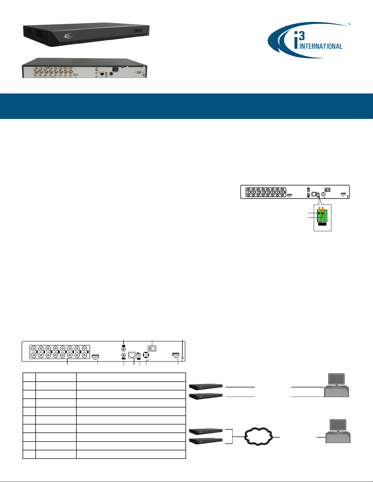
Default IP address:
192.0.0.16 |
Default Subnet mask address:
255.255.255.0.
Login:
i3admin
/ Password:
i3admin
Change your encoder’s default IP Address:
1. Close SRX-Pro Server software by pressing Alt+Shift+Ctrl+F4.
2. Change the IP address of the “Local Area Connection 2” and “Local Area
Connection 3” (if applicable) on your NVR to 192.0.0.XXX to match the
default IP range of your HR16 encoder.
3. Connect your HR16 encoder to RJ45 ports on the back of your i3 NVR
labeled “HR16” or to a gigabit switch (see diagram above). If using a
switch, make sure the encoder and the NVR are on the same network.
4. Connect all your HD-TVI and analog inputs to HR16 encoder and turn the
encoder ON.
5. Restart SRX-Pro Server software. Log in and go to the Setup -> IP Camera
tab.
6. Click ACT Cong Tool icon. If your NVR does not have
Annexxus Conguration Tool, download and install it from
http://i3international.com/download website.
7. In ANNEXXUS Conguration Tool window, a list of active network cameras
and encoders will be displayed. Select your desired encoder in the list.
8. Enter the new IP address and Subnet Mask of the encoder in the Device(s)
Communication Update area and click Update. The new encoder IP
address must match the original range of your SRX-Pro LAN or NIC2/3
card. E.g.If your original SRX-Pro Server’s IP address was 192.138.10.122,
change your HR16 encoder’s IP address to 192.138.10.XXX.
Remember: HR16 encoders (if using more than one) cannot share an IP
address, each encoder requires its own unique IP address.
9. Wait a few moments for a “Success” message in the Result eld.
10. Repeat Steps 7-9 for all detected HR16 encoders in the ACT.
11. Change the IP address of the NIC2/3 back to its original setting (reverse
Step 2).
Ensure you can connect to your encoder using its new IP Address:
12. Open an Internet browser window and enter the new IP Address you have
just assigned to your HR16 camera in Step 8.
13. Enter the default encoder User Name and default Password in the pop-up
login window.
14. Allow the add-on to be installed on your NVR (if applicable). Follow
installation instructions.
15. HR16 encoder interface will be displayed in the Internet Explorer window.
You should be able to see the images of all connected video inputs on the
screen. If you do not see any video streams on screen, call i3 International
technical support team for troubleshooting tips: 1.877.877.7241
Add your HR16 encoder to IP Camera tab in SRX-Pro Server:
16. Ensure that the latest version of GiPi updater is installed on your SRX-Pro
Server. Latest GiPi available from http://i3international.com/download.
Note: SRX-Pro must be closed while GiPi updater is installed. After GiPi
updater installation, start i3 SRX-Pro Server software again.
17. Log In and go to the Setup -> IP Camera tab.
18. Click the Search & Add to display connected cameras and encoders.
19. Select the detected HR16 encoder in the list and click Select.
20. In the Select IP Camera window, enter the default HR16 encoder User
Name: i3admin and default Password: i3admin, then click Add. The
selected encoder with all connected HD-TVI/analog inputs will be added to
the IP Camera list.
21. Assign each input to the SRX-Pro video channel in the Ch In. column.