This service manual is intended for qualified service technicians; it is not meant for the casual do-it-yourselfer. Qualified
technicians have the necessary test equipment and tools, and have been trained to properly and safely repair complex
products such as those covered by this manual.
Improperly performed repairs can adversely affect the safety and reliability of the product and may void the warranty. If
you are not qualified to perform the repair of this product properly and safely, you should not risk trying to do so and
refer the repair to a qualified service technician.
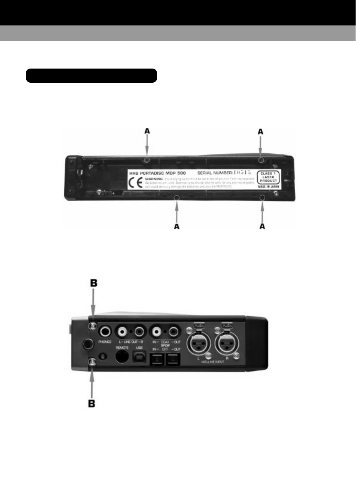
This appliance is classified as a CLASS 1 LASER product, the CLASS 1 LASER product marking is on the rear of the
unit inside the battery compartment.
This equipment fully complies with 21 CFR 1040.10 and 1040.11
CAUTION: Invisible laser radiation when the unit is disassembled, avoid exposure to beam.
3
2
CONTENTS
PORTADISC MDP500 MiniDisc Recorder
SAFETY INFORMATION
1. DISASSEMBLY INSTRUCTIONS . . . . . . . . 5-12
Removing The Top & Bottom Panels . . . . . . . . . . 5-6
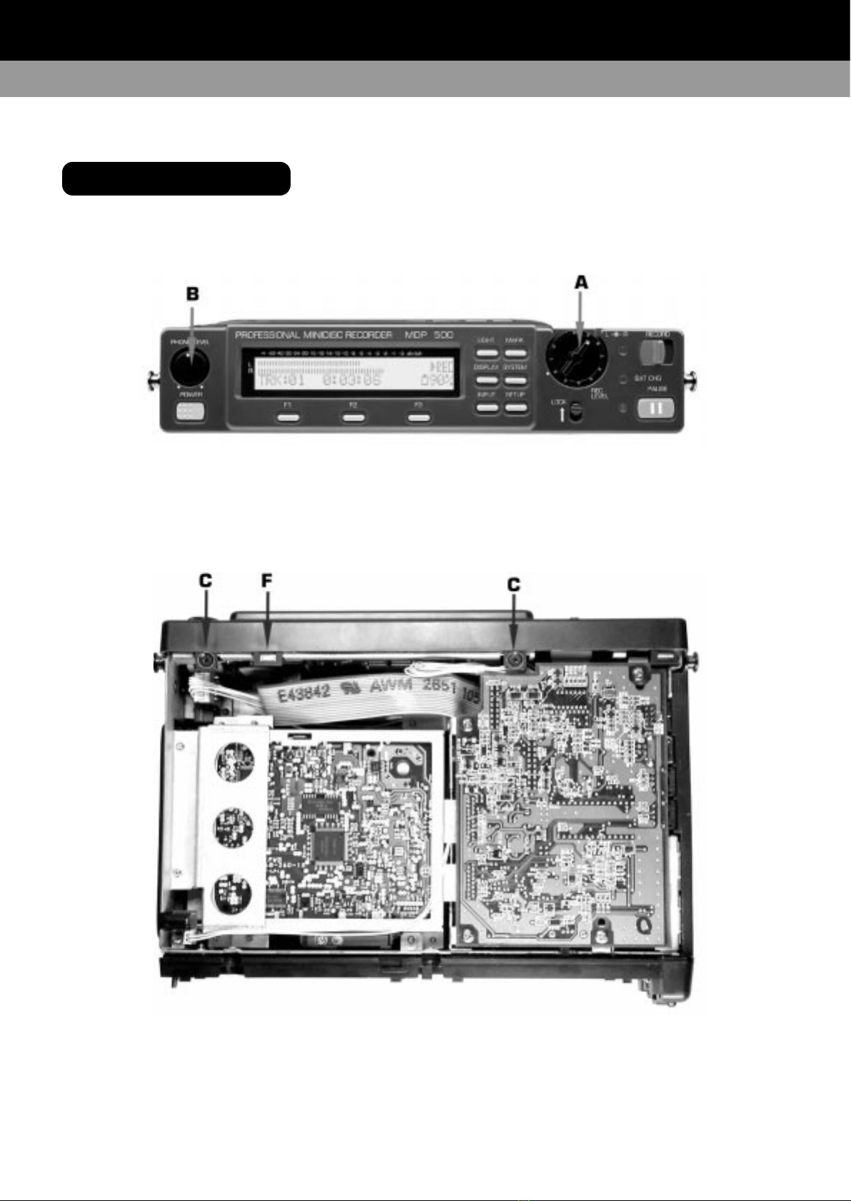
Removing The Front Panel . . . . . . . . . . . . . . . . . 7-8
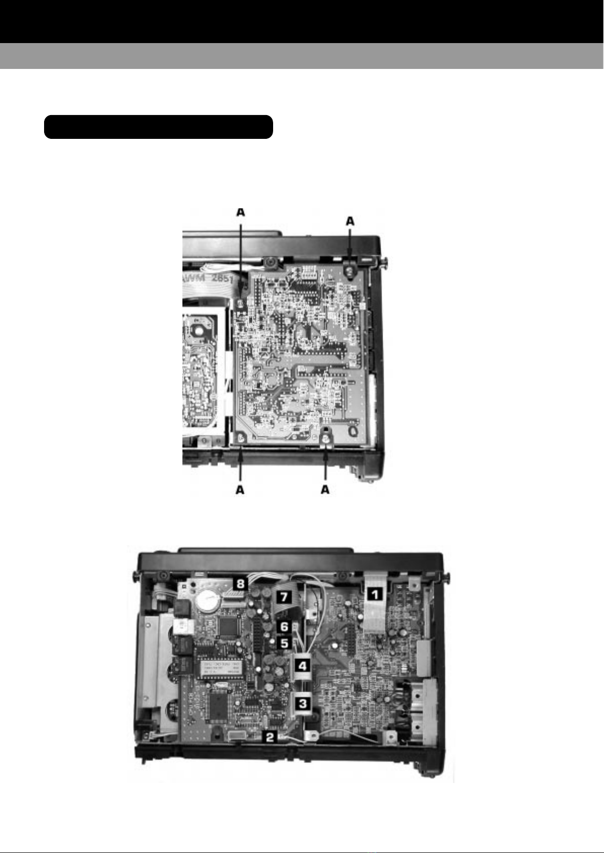
Removing The Main CPU Circuit Board . . . . . . . . . . 9
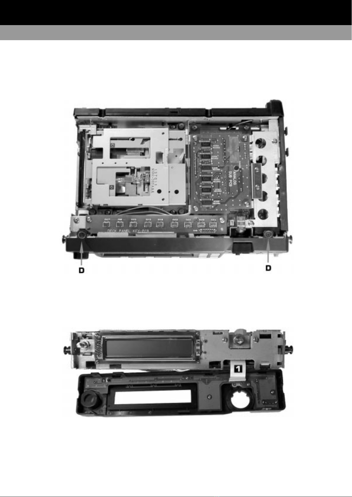
Removng The MD Mechanism . . . . . . . . . . . . . . 10
Removing The Analog Main & Sub Circuit Boards 11-12
2. BLOCK DIAGRAM . . . . . . . . . . . . . . . . . . . . 13
3. CIRCUIT DIAGRAMS . . . . . . . . . . . . . . . . 15-21
CPU . . . . . . . . . . . . . . . . . . . . . . . . . . . . . . . . 15
Power Supply CPU Board . . . . . . . . . . . . . . . . . . 17
Analog Inputs . . . . . . . . . . . . . . . . . . . . . . . . . . 19
Analog Output & Digital Coax I/O . . . . . . . . . . . . . 21
4. PCB LAYOUTS . . . . . . . . . . . . . . . . . . . . 24-33
CPU PCB Component Side . . . . . . . . . . . . . . . . . 24
CPU PCB Solder Side . . . . . . . . . . . . . . . . . . . . . 25
Analog Main Solder Side . . . . . . . . . . . . . . . . . . 28
Analog Main Component Side . . . . . . . . . . . . . . . 29
Analog Sub PCB Solder Side . . . . . . . . . . . . . . . . 32
Analog Sub PCB Component Side . . . . . . . . . . . . 33
Front Panel PCB Parts Side . . . . . . . . . . . . . . . . 35
Front Panel PCB Solder Side . . . . . . . . . . . . . . . . 35
Deck Panel PCB . . . . . . . . . . . . . . . . . . . . . . . . 37
5. RESET INFORMATION . . . . . . . . . . . . . . . . . 39
6. TEST MODE & ALIGNMENT . . . . . . . . . . 41-47
Entering Test Mode . . . . . . . . . . . . . . . . . . . . . . 41
Switch Test Mode . . . . . . . . . . . . . . . . . . . . . . . 41
Mechanism Alignment Test Mode . . . . . . . . . . . . 41
Tools For Alignment . . . . . . . . . . . . . . . . . . . . . . 42
Button Operation During Alignment Test Mode . . . 42
The Alignment Modes . . . . . . . . . . . . . . . . . . . . 42
Test Mode Displays . . . . . . . . . . . . . . . . . . . . . . 43
Temperature Compensation Offset Adjustment . . . 43
Laser Power Adjustment . . . . . . . . . . . . . . . . . . 44
Traverse Adjustment . . . . . . . . . . . . . . . . . . . 44-45
Focus Bias Adjustment . . . . . . . . . . . . . . . . . 45-46
Error Rate Confirmation . . . . . . . . . . . . . . . . . . . 46
Creating A Continuously Recorded Test Disc . . . . . 47
7. IC INFORMATION . . . . . . . . . . . . . . . . . . 49-50
8. PARTS LIST . . . . . . . . . . . . . . . . . . . . . . 51-53
Main Frame . . . . . . . . . . . . . . . . . . . . . . . . 51-52
CPU Unit . . . . . . . . . . . . . . . . . . . . . . . . . . . . . 52
Analog Main Unit . . . . . . . . . . . . . . . . . . . . . . . 53
Analog Sub Unit . . . . . . . . . . . . . . . . . . . . . . . . 53
9. IDENTIFICATION OF PARTS . . . . . . . . . . . 55-58
Top Panel . . . . . . . . . . . . . . . . . . . . . . . . . . . . . 55
Front Panel . . . . . . . . . . . . . . . . . . . . . . . . . . . 56
Side Panels . . . . . . . . . . . . . . . . . . . . . . . . . . . 57
LCD Display . . . . . . . . . . . . . . . . . . . . . . . . . . . . 58
10. TECHNICAL DATA . . . . . . . . . . . . . . . . . . . 59
CONTENTS