Hi-view Effio-E User manual

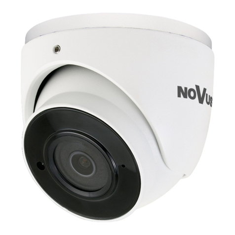
IR Dome Camera
Instruction Manual
Before operating the unit, please read this manual thoroughly
and retain it for future reference.

DO NOT ATTEMPT TO DISASSEMBLE THE
CAMERA.
Safety Precautions
Risk of Electric Shock, Do not Open
CAUTION: TO REDUCE THE RISK OF ELECTRIC
SHOCK, DO NOT REMOVE COVER NO USER-
SERVICEABLE PARTS INSIDE REFER SERVICING
TO QUALIFIED SERVICE PERSON
This symbol is intended to alert the user to the presence of
uninsulated dangerous voltage within the product's enclosure that
may be of sufficient magnitude to constitute a risk of electric shock
to persons.
This symbol is intended to alert the user to the presence of
important operation and maintenance instructions in the literature
accompanying the appliance.
Warning
1This product has patented for configuration and appearance
design, and copying is not permitted.
2If this product fails to operate normally, contact authorized distributor.
Never disassemble or modify the product in any way. Problem caused
by unauthorized user disassembly or repairs are out of warranty
scope.
3Electromagnetic fields in specific frequency may cause image
interference.
4Be sure to use only the standard adapter which is specified in the
specification sheet. Using other adapter could cause fire, electric
shock or damage to produce. 1

1Do not drop objects on the products or apply strong shock to it.
Keep it away from a location subject to excessive vibration or
magnetic-field interference.
2Do not install in a location subject to high temperature (over
122°F or +50℃ ), low temperature(below 14°F or -20℃), or
may cause fire.
3If want to relocate the installed products, be sure to turn off the
power before moving or reinstalling it.
4Remove the power plug from the outlet when there is a lightning
storm. Neglecting to do so may cause fire or damage to the
product.
5Avoid a location which is exposed to direct sunlight, or near heat
sources. Neglecting to do so may cause fire.
6Install in a well-ventilated location.
5Incorrectly connecting the power supply may result in fire,
electric shock or damage to produce as well.
6Do not connect multiple cameras to a single adapter. Exceeding
the capacity may cause abnormal heat generation or fire.
7Securely plug the power cord into power receptacle. A loose
connection may result in fire.
8When installing the camera on a wall or ceiling, fasten it safely
and securely. A falling camera may cause personal injury.
9Do not place conductive objects (e.g. screwdrivers, coins, metal
things, etc.) or containers filled with water on top of the camera.
10 Do not install the unit in humid, dusty, or sooty locations. Doing
so may cause personal injury.
11 If any unusual smell or smoke comes from the unit, please stop
using the product. In such case, please immediately disconnect
the power source and contact local authorized distributor.
12 Do not install the unit in humid, dusty, or sooty locations. Doing
so may cause personal injury.
Cautions
2

7Avoid aiming the camera directly towards extremely bright
objects such as the sun, as this may damage the CCD image
sensor.
Read these instructions
Keep these instructions for later use.
Pay attention that all warnings should be adhered to.
Follow all instruction.
Do not use this product near water.
Clean only with dry cloth.
Do not block any ventilation openings.
Do not install near any heat sources such as radiations, heat
registers, or other product (including amplifiers) that produce heat.
Protect the power cord from being walked on or pinched
particularly at plugs, convenience receptacles, and the point
where they exit from the apparatus.
Only use attachment/accessories specified by the manufacturer.
For added protection for this product during a lightning storm, or
when it is left unattended and unused for long periods of time,
unplug it from the wall outlet and disconnect the antenna or
cable system.
Refer all servicing to qualified service personnel. Servicing is
required when the product has been damaged in any way, such
as power-supply cord or plug is damaged, liquid has been spilled
or objects have fallen into the product has been exposed to rain
or moisture, does not operate normally, or has been dropped.
Do not operate the camera beyond its temperature, humidity or
power source ratings. Operating temperature: 14F-122F(-20℃-
50℃) ;Humidity﹤85%。
Do not point the camera towards the sun; do not operate camera
in a spotlight, highlight, or reflection environment.
Do not install or use the camera in the following places.
a) In excessive heat or cold locations
1
2
3
4
5
6
7
8
9
10
11
12
13
14
15
Important Safety Instructions
3

b) In damp or dusty locations
c) In a place exposed to rain
d) In a place subject to vibration
f) In a place exposed to fluorescent light
e) Near a source of electromagnetic radiation (wireless/radio
or television emission)
g) In a place under poor lighting condition
The laser beam may damage CCD. Do not project the laser
beam directly into the lens of the camera.
16
4

Chapter 1 Overview
Instruction
This is an IR dome camera. It saves costly installation time and provides
more convenience and functions.
Built-in 2.8-12mm IR 2.0 Megapixel Lens
Ceiling Mount and Wall mount Design
Built-in ICR
Separated IR LED for Heat Insulation
IR LED:¢3×42pcs, IR Range:20m/60ft
External OSD Setup
Video Out Port for CCTV Multi-Tester
Supported DC 12V/AC 24V (Optional)5
Table of Contents
Chapter 1 Overview 5-9
Instruction 5
Specification 6-8
Package 8
Product Parts
9
Connection 10
Chapter 2 Operation Instruction
10 12-
Installation
10 12-
Before Installation 10
Cautions for Installation 11
Chapter 3 Typical CCD Phenomena 13
Installing the Camera 11
Adjustment of Function 12
Adjustment of Monitoring Direction 12
Chapter 4 Common Troubleshooting 14
Chapter 5 Current Maintenance 14

Specification
6
Model No.
Effio-E
Effio-P
Camera
TV System
NTSC
PAL
NTSC
PAL
CCD Sensor
SONY 1/3” Super HAD Ⅱ CCD
SONY 1/3” EX-view HAD Ⅱ CCD
DSP
Effio-E
Effio-P
Effective Pixel
976(H)×494(V)
976 (H)×582 (V)
976(H)×494(V)
976 (H)×582 (V)
Scan
2:1 Interlace
SNYC System
Internal / External
Resolution
650TVL(Color)
700TVL(Black & White)
Video Output
BNC 1.0Vp-p75ohm
Burst Level
0.286Vp-p
Camera
S/N Ratio
>52dB
Minimum
Illumination
0.01Lux of F1.2(Color)
0.001Lux of F1.2(Black &
White)
0.01Lux of F1.2(Color)
0.0002Lux of F1.2(Black &
White)
Electronic
Shutter
Auto / Manual
1/50-1/100,000 sec
Slow Shutter (Sens-up), WDR
Menu
Expose Control
AES / DC Drive Auto Iris / Video Drive Auto Iris / Auto / Manual
/ AIS
White Balance
ATW / Push / USER1 / User2 /
Manual / Push Lock
ATW / Push / USER1 / User2 /
ANTI Color Rolling
/ Manual / Push Lock
Auto White
Balance Range
—
ATW pull-in Color Temperature
Range 3200 - 9500K
AGC
Auto / Manual
Off / Low / Middle / High
OSD
Yes ( Cover-Opened Adjustment )

7
Menu
D/N Switch
Auto / Color / Black & White / EXT1/ EXT2
IR
Smart IR
BLC
OFF / BLC / HLC
Usable While WDR OFF
HLC
—
OFF / ON
Image
Mirror/Lightness/Contrast/Sh
arpness/Color/Gain
—
E-zoom
—
OFF / ON (X1 - X256)
Digital Image
Stabilizer
—
OFF / ON
Digital WDR
OFF / ON 128×WDR(52dB)
—
WDR
—
OFF / ON
Flicker- Less
—
OFF / ON
(External Control, Optional)
ATR
—
OFF / ON
Menu
Motion Detection
OFF / ON
OFF / ON
Privacy Masking
OFF / ON
OFF / ON (15 Masks)
Mirror
ON / OFF (Left/Right)
ON / OFF (Left/Right/Up/Down)
NR
2D NR
2D / 3D NR
Sharpness
1 - 255 A djustable
Menu Language
Chinese / English / Japanese / German / French / Russian /
Portuguese / Spanish
Lens
Model
1/2.7” 2.8-12mm 2MP IR
Angle of View
92° ~ 27.2°
Vari-focal
Adjustment
Cover-Opened A djustment

8
Check the contents of package. The following items are included.
One User Manual
One dome camera
Three fixed screws
One L-type screw driver
Package
Lens
Lens Mount
φ14
Day & Night
IR Cut Filter with A uto Switch
Iris
Fixed
General
Power Supplyener
DC 12V 10%±, Support DC12V/AC24V Dual Voltage Power Supply
Power
Consumption
Max. 1W (Max. 7 W with IR Cut Filter ON)
Operating
Conditions
-20°C ~ 50°C
IR Light
¢3×42pcs IR LEDs
IR Range
20m/60ft 3m/10ft±
Bracket
3-AXIS Concealed Cable Bracket
Dimension
106.5mm×106.5mm×109.3mm
Weight
460g
*Design and Specifications are subject to change without notice.

Product Parts
9
1
Fixed Holder
Connerting Part
3
Bottom Cover Button
Fixed Holder — Fixing the camera to the ceiling or wall
Connecting part — Fixing the camera body to the connector and
fixing the monitoring direction
Bottom Cover Button — Opening the IR LED Shield
IR LED Shield — Sealing the IR LEDs
OSD Setup — Setting the functions
Video Out Port — Connecting the CCTV multi-tester to check the
image
Lens Focus Lever — Adjusting the focal length of lens
Lens Zoom Lever — Adjusting the focal length of lens
Function of product parts
5
4
OSD Setup
IR LED Shield
6Video Out Port
8Lens Zoom Lever
Lens Focus Lever
7
1
2
3
4
5
6
7
8
2

10
Chapter 2 Operating Instruction
Connection
1Connect one end of the BNC Cable to the terminals of the monitor.
2Connect the other end of the BNC Cable to the VIDEO OUT
3Then, plug in the power adapter into the power receptacle. The
screen will be displayed when the monitor is on.
1Make sure the installation location can support 5 times the total
weight of the bullet camera.
2Be careful not to let the cable be jammed in inappropriate places
or to let the insulation covering of the cable peel off during
installation. This may result in malfunction or a fire hazard.
3Make sure that nobody is beneath the installation location, and
remove the camera if anything urgent needs dealing there.
Read the cautions before installation:
Installation
Before Installation

Installation process is illustrated as below
Installing the Camera
11
Step2: Hold the connecting part, and put it upwards, rotate and mount
it to the hooks on the connector, Pay attention to those 4 bulges. They
match the hooks of the fixed holder.
*Pay attention to the cable trough. Put it in the direction of power
supply if cables exit there.
Step1: The side of the fixed holder facing up, to be mounted to the
ceiling or wall with 3 connector screws.
Cautions for Installation
1Allow the cable to pass through the hole in the middle
before mounting the camera to the fixed holder.
2If passing through the side, the cable must be put at the cable
trough first before the camera is mounted.
3Make sure that the camera has been well mounted to the hooks
after installation. Reverse rotation may help confirm it. It is
completely done when uneasy to release the camera.
Cable Trough

Adjustment of Monitoring Direction
1Manually hold the dome body, which can be rotated 355°in
horizontal direction, 60°in vertical direction.
2Rotate the dome body in one direction, then the other. (eg.
Rotate it in horizontal direction firstly, then in vertical direction).
This dome camera is with internal self-locking function. The
latching points can be found when the dome is rotated, and the
corresponding angle of each point is 2 degrees.
1
Use the video out port to connect the multi-tester with the camera,
and check the image on screen.
Press the bottom cover button. Pull it downwards to open bottom cover.
2Adjust the focal length with the lens zoom level and lens focus
level according to need. After you get the clear image, tighten
those two screws.
3Set the functions by OSD setup.
4Reassemble the bottom cover upwards.
Adjustment of Function
Note: After the adjustment of monitoring direction is done, fasten the
connecting part to fix the surveillance position.
3There are limitative block in both rotation directions.
4Be cautious that trying too hard may damage the block, and that
can consequently cause damage to the cables inside the dome.
355° 60°
12

Chapter 3 Typical CCD Phenomena
The following effects on the monitor screen are characteristic of
CCD cameras.
They do not indicate any fault with the camera.
This occurs when shooting a very bright object such as electric
lighting, the sun, or a strong reflection. This phenomenon is caused
by an electric charge induced by infrared radiation deep in the
photosensor. It appears as a vertical smear, since the CCD imaging
element uses an interline transfer system.
This is a phenomenon is which the light from very bright objects
appears to overflow into neighboring areas in an image.
If strong light enters a wide area of the screen, the screen may
become dark. This is not a malfunction. If this occurs, avoid strong
light or adjust the lens iris to reduce the light amount.
While CCD image pickup device is made by an accurate technique,
imperceptible speckles may rarely come up on the screen due to
cosmic rays and so on. This is connected to the principle of CCD
mage pickup device, not a malfunction. And the white speckles are
easy to come up in the following conditions.
Smear
When you shoot vertical stripes or lines, they may appear jagged.
Vertical aliasing
A CCD image sensor consists of an array of individual sensor
elements (Pixels), A malfunctioning sensor element will cause a
single pixel blemish in the picture. (This is generally not a problem.)
Blemishes
White speckles
Blooming
Note
Using the camera in high temperature
When turning up the gain
13

Chapter 4 Common Troubleshooting
If encounter troubles in use of the bullet camera, please refer to the
following instructions. For more information, please consult nearby
local authorized distributor.
Chapter 5 Current Maintenance
1In use of the camera, regularly clean the dust and dirt on the lens
surface of the camera to keep good clarity of image.
2Clean the camera with dry and soft cloth. For stubborn dirt,
please wipe it with a cloth dipped in a little neutral detergent,
and then dry the camera with cloth.
3Be careful not to use volatile impregnant like thinner, alcohol,
benzene or pesticide, etc. to clean the camera, for that can
damage the surface coating, and even weaken the function and
performance of the camera.
Troubles
Solution
No Video Output
Check the power supply, or the connection among the
cable, camera and monitor.
Malfunction
Check whether the camera is connected to the DC 12V
power supply.
Light Image
Adjust the display contrast of the monitor; Change the
location if the camera is exposed to intense light.
Dark Image
Adjust the Brightness.
The situations below are not malfunction of the camera.
Vertical Streak
It may appear when the camera is exposed to intense light.
Fixed Image
Clutter
When the camera is in high temperature environment, there
may be fixed image clutter on the entire monitor screen.
Jagged Image
When shooting at a ribbon-like object, a straight line or
something of similar patterns, the image displayed on the
monitor may be serrated.
14
This manual suits for next models
2
Table of contents
Other Hi-view Security Camera manuals

