Table of Content
Table of Content ...............................................................................................................2
Preface...............................................................................................................................3
Safety Warnings.................................................................................................................3
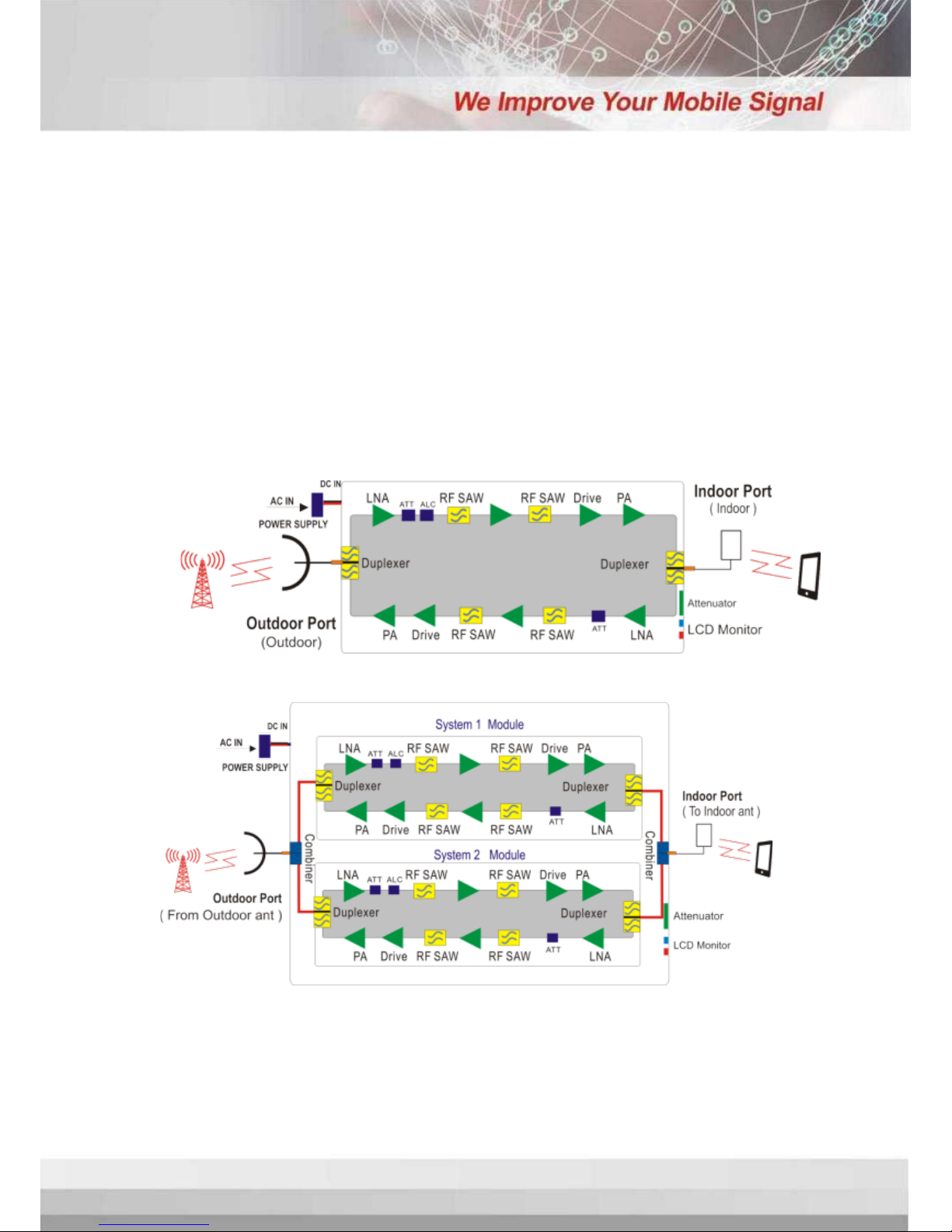
Overview ............................................................................................................................4
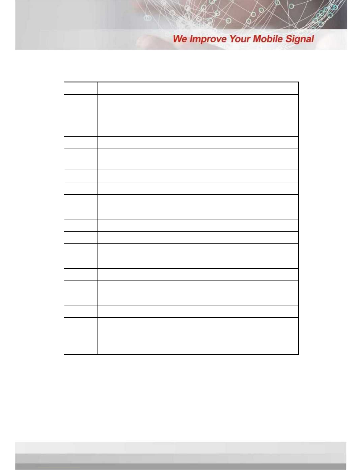
Glossary of Terms...............................................................................................................5
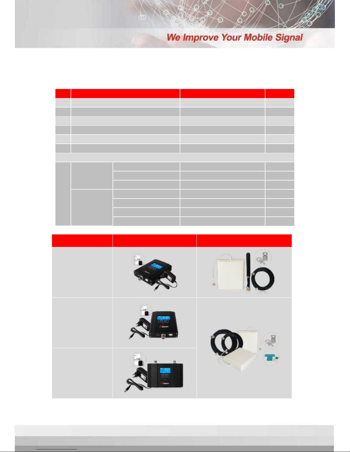
Package Contents............................................................................................................6
Features ..............................................................................................................................8
Booster’s Port Description.................................................................................................9
LCD Introduction ...............................................................................................................9
Control Button Operation...............................................................................................11
Manual Gain Control (MGC).........................................................................................11
InstallHiboost Booster System .........................................................................................12
Before You Install......................................................................................................12
Installation Overview ...............................................................................................12
Step 1. Install Outdoor Antenna......................................................................14
Step 2.Install Indoor Antenna..........................................................................17
Step 3.Install Signal Booster..............................................................................19
Step 4.Booster Commissioning........................................................................20
Main Specifications.........................................................................................................25
Troubleshooting...............................................................................................................26
Product Warranty............................................................................................................27
Huaptec Contact Details...............................................................................................27
2