Hickory Springs TRANSITIONAL TS150 User manual

TS150
TS250
TS300
Adjustable Base Owners Manual
HS Manufacturing, LLC, a subsidiary of Hickory Springs Manufacturing Company | P/N 303007002 REV. Sept 2018


ADVISORY
IMPORTANT INFORMATION
READ THE FOLLOWING INFORMATION CAREFULLY BEFORE USING THIS PRODUCT
ii
FOR OPTIMUM ADJUSTABLE BASE OPERATION, USE A GROUNDED ELECTRICAL SURGE
PROTECTION DEVICE (NOT INCLUDED). FAILURE TO USE A SURGE PROTECTION DEVICE
COULD COMPROMISE SAFETY OR CAUSE PRODUCT MALFUNCTION.
ELECTRICAL RATING
Electrical components are rated for 100-240V, 50-60Hz, 1.6 amp.
ELECTRICAL GROUNDING
This product is equipped with a polarized or grounded electrical power cord. The power cord will only fit into
a grounded electrical surge protection device (not included) or grounded electrical outlet.
WARRANTY WARNING
Do not open any control boxes, motors, or remote control devices (with the exception of the remote control
and power backup battery compartments). The product warranty will be void if these components are
tampered with. Do not attempt to alter component wiring or adjust or modify the structure of the product in
any way or the warranty will be void. Any repair or replacement of base parts must be done by authorized
personnel.
LUBRICATION
This product is designed to be maintenance free. The lift motors are permanently lubricated and sealed –
no additional lubrication is required. Do not apply lubricant to lift motor lead screws or any nylon nuts, as
the base may inadvertently creep downward from the elevated position.
PRODUCT RATINGS
The base lift motors are not designed for continuous use. Reliable operation and full life expectancy will be
realized as long as the lift motors do not operate any more than four (4) minutes over a forty (40) minute
period, or approximately 10% duty cycle. Note: massage equipped bases are not designed for
continuous massage operation. Massage systems are rated for a maximum of 2 hours use within a
6 hour period. Any attempt to circumvent or exceed product ratings will shorten the life expectancy of the
product and may void the warranty.
The rated weight restrictions for TransitionalTM adjustable bases are 600 lbs (281 kg) for TS150, 700 lbs
(317kg) for TS250, and 800 lbs (362 kg) for TS300. The base will structurally support the recommended weight
distributed evenly across the head and foot sections. This product is not designed to support or lift this
amount in the head or foot sections alone. Note: Exceeding the recommended weight restrictions
could damage the base and void the warranty.
For best performance, consumers should enter and exit the adjustable base with the base in the flat
(horizontal) position. DO NOT SIT ON THE HEAD OR FOOT SECTIONS WHILE IN THE RAISED
POSITION.
UL (Underwriters Laboratories) recognized components
CFR 1633 approved for use with most mattresses
Assembled in the USA


TABLE OF CONTENTS
Advisories ...............................................................................................................…
Included Parts ...................................................................................................….….
Leg Installation ...................................................................................................….…
Battery Backup & Power Connection .................................................................….…
Wireless Remote Setup.....................................................................................….….
Bluetooth Setup (TS300).........................................................................................…
Base Setup........................................................................................................….….
Mattress Retainer Installation............................................................................….….
Trim Board Installation (TS250 and TS300)................................................….…...…
Split Bed Setup....................................................................................................….
Headboard Installation….…………….…….…….….….…………….……….………..
TS150 Wireless Remote Overview.....................................................................…
TS250/TS300 Wireless Remote Overview................................................................14
Optional Accessories.............................................................................................…16
ii
4
5
6
7
8
9
9
10
11
12
13
INSTALLATION
4
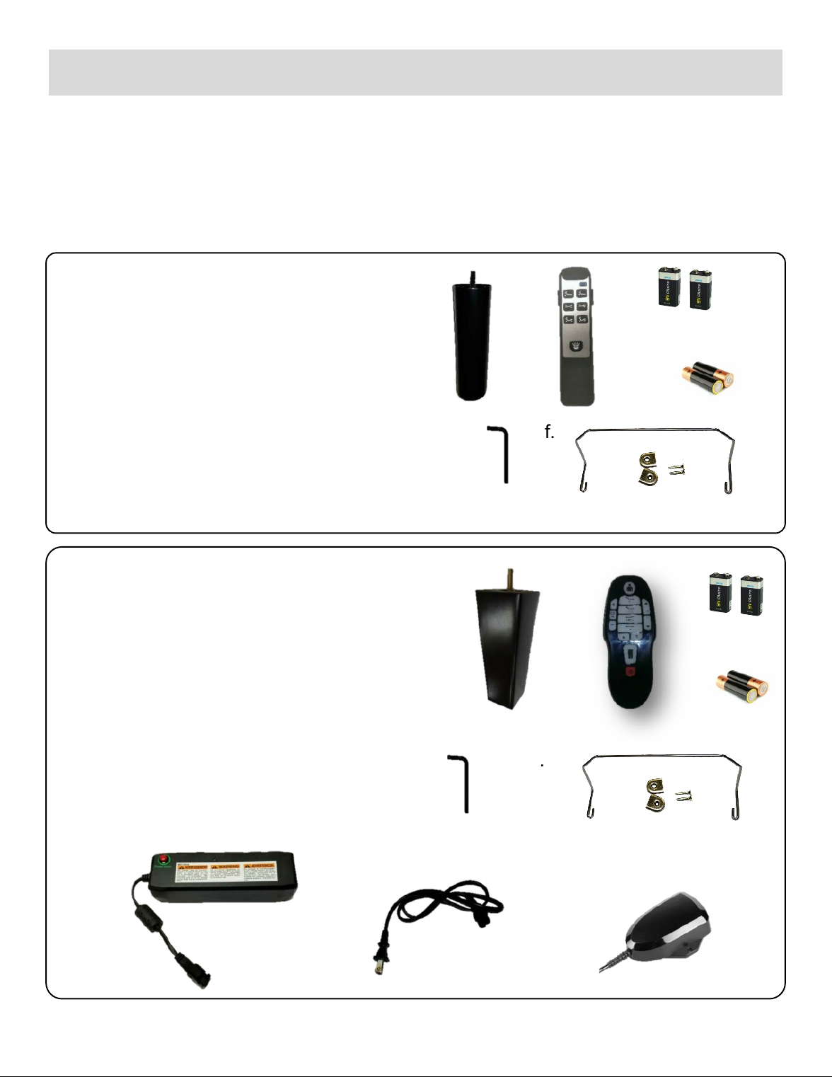
TS150:
a. Four (4) Metal Support Legs
b. One (1) Wireless Remote Control
c. Two (2) 9V Batteries
d. Two (2) AAA Batteries
e. One (1) Hex L-key
f. One (1) Mattress Retainer Bar
TS250 & TS300:
a. Four (4) Wood Support Legs
b. One (1) Wireless Remote Control
c. Two (2) 9V Batteries
d. Two (2) AAA Batteries
e. One (1) Hex L-key
f. Mattress Retainer Bar
(attached to base)
g. AC Adapter/Battery Backup
h. Power Cord
i. Bluetooth Receiver (TS300 only)
a.
e.
c.
d.
f.
b.
a. b. c.
d.
e. f.
g.
h.
i.
Before discarding any packing materials, verify the following items have been included:
To install and setup your Transitional Sleep Adjustable Base, complete the numbered procedure
indicated below and on the following pages.
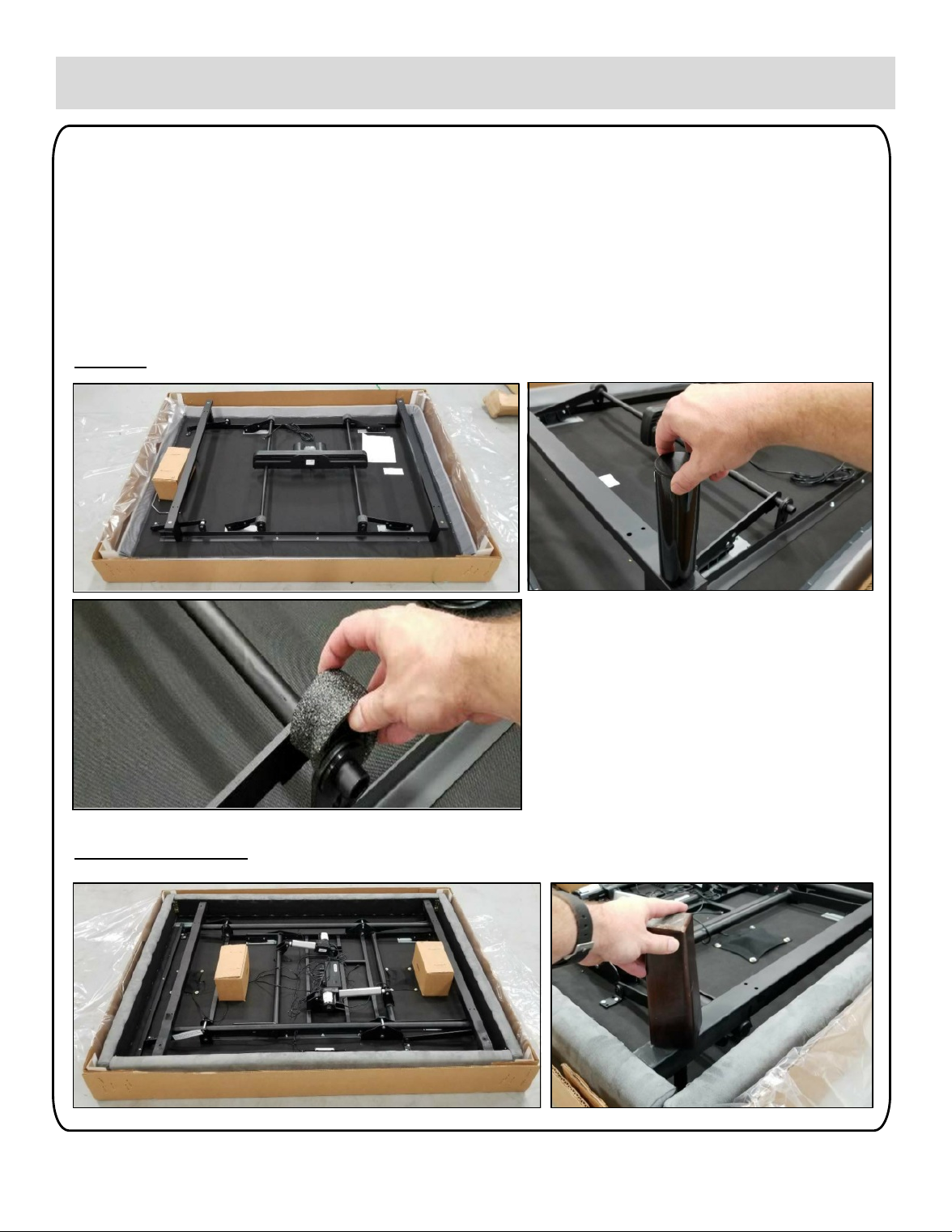
TS250 & TS300
Step 1: Unpackaging and Leg Installation
a. Lay shipping box flat on floor (top up) and open. Set all loose parts to the side.
Open smaller box and remove legs.
b. Install legs to base frame by screwing them into the threaded inserts in the frame.
Do not over-tighten.
NOTE: Remove foam packaging from the ends of the lift tubes (4 places)
5
INSTALLATION
TS150

BATTERY
COMPARTMENT
TS250 & TS300
Step 2: Battery Backup and Power Supply
a. Locate backup battery compartment and connect 9 volt batteries (included).
b. Connect control box cord and power cord to AC adapter (TS250 & TS300.)
c. Plug power cord into grounded electrical outlet. Use of a electrical surge
protector (not included) is recommended.
6
TS150
INSTALLATION
BATTERY BOX BATTERY
COMPARTMENT
CONNECT
PLUG HERE
CONNECTED MOTOR CORD
TO BATTERY BOX
PLUG BASE INTO POWER OUTLET
INSERT POWER
CORD HERE
PLUG BASE INTO POWER OUTLET

TS250 & TS300
Sync can be completed in one of two ways:
1. Press/hold TV and LOUNGE buttons at the same
time, then press/release
RESET button on control box
2. Within first 10 seconds of control box being plugged
into power supply,
press/hold TV and LOUNGE buttons at the same
time
NOTE: For remote to sync with base, it must be in the
Factory Preset mode. To confirm remote is in Factory
Preset mode, press/hold TV and LOUNGE buttons at
the same time. If TV and LOUNGE buttons are only
buttons illuminated (as shown in photo to right), then
remote is in correct mode. If all buttons on remote are
illuminated, the remote is in the incorrect mode and
needs to be reset to Factory Preset mode (see
instructions on page 15)
INSTALLATION
Step 3: Remote Setup
The wireless remote is synced to the electronics controller at the factory. If however, the remote is
not synced, or becomes unsynced, follow the steps below:
TS150
7
Press/hold HEAD DOWN and FOOT UP buttons at the same time, then
press/release CODING button on motor housing

INSTALLATION
8
Step 4: Bluetooth Setup (TS300)
To Set Up Bluetooth Control
a. Plug Bluetooth Module into slot in Control Box
b. Sync Bluetooth Module to Wireless Remote :
Press/hold TV and LOUNGE buttons on remote at the
same time, then press/release RESET button on front
of Bluetooth module.
c. Bluetooth app for iPhone and iPad can be
downloaded from Apple Store, under TSS
Remote. For iOS 8.1.2 and newer.
Bluetooth app for Android can be downloaded
from Google Play Store, under TSS Remote.
NOTE: For remote to sync with base, it must be in the Factory Preset mode. To confirm
remote is in Factory Preset mode, press/hold TV and LOUNGE buttons at the same time.
If TV and LOUNGE buttons are only buttons illuminated (as shown in photo above), then
remote is in correct mode. If all buttons on remote are illuminated, the remote is in the
incorrect mode and needs to be reset to Factory Preset mode (see instructions on page
15)
INSTALLATION
Step 5: Base Setup
a. Inspect underside of base and confirm all cables are secured and connections are tight.
b. Confirm that lift motors are working properly and that all other applicable functions (massage,
LED lights, and/or Bluetooth) are operational.
c. Unplug power cord from outlet.
d. Lift base out of box by metal frame and set on legs. **Always use 2 people to lift base.**
9
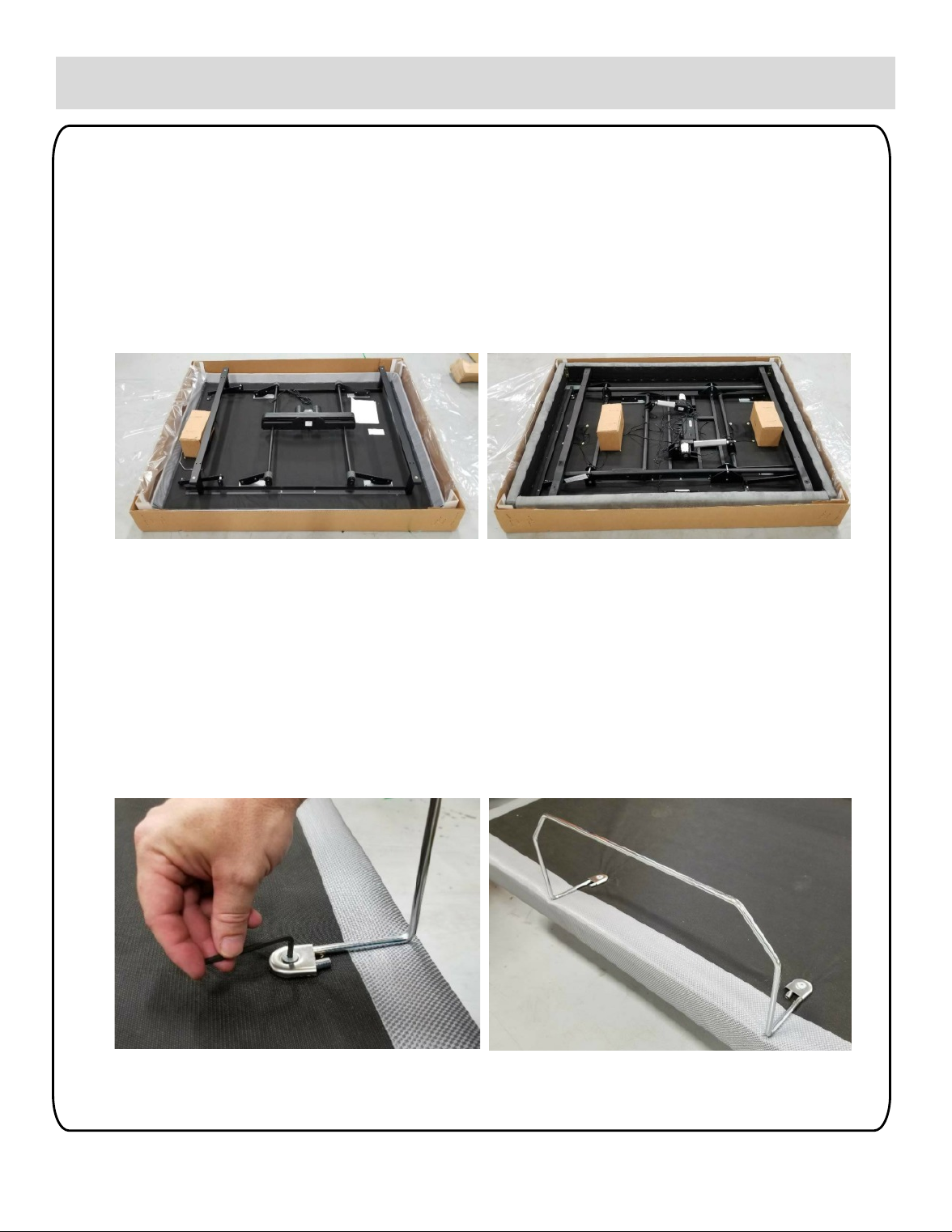
Step 6: Mattress Retainer Installation
The mattress retainer is shipped loose on the TS150 and attached to the base, upside down, on the
TS250 & TS300. To assemble:
a. If mattress retainer attached to base, remove retainer by loosening screws and capture
washers with hex L-key.
b. Position retainer in correct location and install using capture washers and screws
c. Tighten screws and capture washers.
Note: The base comes standard with threaded inserts to add a second mattress retainer
at the head. See page 16 for information on ordering a second retainer.
INSTALLATION
10
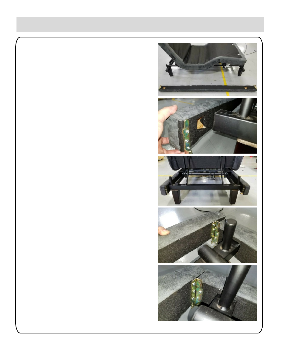
Step 7: Trim Boards (TS250 & TS300)
The trim boards are installed at the factory.
However, if the boards become loose or are
uninstalled, the following procedure should be
used to reinstall.
a. Raise head and foot section of base to
highest positions.
b. Attach side boards
a. Position board so that the shorter
overhand is at the head and metal
brackets are as shown in the photos to
the right.
b. Align square cutouts in board with
square tube of frame.
c. Push boards onto frame.
Note: Side boards will be secured once end
boards are installed.
c. Attach end boards
a. Position end board at head or foot
against side boards.
b. Slide end board down boards so that
metal fittings engage.
Trim board frame is now fully locked together
and securely mounted to the metal frame.

INSTALLATION
Step 8: Split Bed Setup
Two (2) Twin XL or Split California King bases can be set up next to one other to create a King or
California King adjustable unit. These bases can operate independently or be synced together to
operate as one unit.
To operate two bases simultaneously with one remote, sync wireless remote to
both bases (sync instructions shown on page 7).
On the TS250 and TS300, two remotes can be used interchangeably to operate synced bases.
This is done by matching two remotes together.
To Match Remotes
• Press/hold TV and LOUNGE on remote A at the same time , then press/release
RESET on control box A
• Press/hold TV and LOUNGE on remote A at the same time , then press/release
RESET on control box B
• Press/hold 0 GRAVITY and FLAT on remote B at the same time, then press
Press TV and LOUNGE on remote A at the same time
Note: remotes must be in Factory Preset Mode (see Memory Feature section on
page 15) to match.
To Unmatch Remotes
• Press INTENSITY DOWN (-) and POSITION DOWN ( POS ▼) on remote B at
the same time to separate.
NOTE: Remotes must be in Factory Preset mode to match.
To confirm remote is in Factory Preset mode, press/hold TV and LOUNGE buttons at
the same time. If TV and LOUNGE buttons are only buttons illuminated, then remote is
in correct mode. If all buttons on remote are illuminated, the remote is in the incorrect
mode and needs to be reset to Factory Preset mode (see instructions on page 15)
The bases can also be connected using the optional connection bars (sold separately).See page
16 for more information.
11

INSTALLATION
Step 9: Headboard and Footboard Bracket (Optional)
To attach a headboard and/or footboard to your adjustable base, the optional headboard and/or
footboard brackets must be purchased from the manufacturer. See page 16 for more information.
Parts:
•(1) RH Mounting Bracket
•(1) LH Mounting Bracket
•(2) Support Brackets
•(4) 4-1/2” Hex Bolts
•(4) 1-1/2” Hex Bolts
•(4) Spacers
•(8) Flat Washers
•(8) Hex Nuts
Tools Required:
•(2) 7/16” Open End Wrenches or (1) Wrench
and (1) 7/16” Socket
•Attach support brackets to base frame using (4)
4-1/2” bolts, (4) spacers, (4) flat washers, and
(4) nuts. Spacers should be installed between
underside of chassis frame and top of support
bracket. Washers are to be used against slot
on underside of support bracket. Do not fully
tighten, to allow bracket to slide along slot.
•Attach mounting brackets to support brackets
using (4) 1-1/2” bolts, (4) flat washers, and (4)
nuts. Washers are to be used at slot on front
side of mounting bracket. Do not fully tighten,
to allow mounting bracket to slide along slots.
•Match mounting plate to headboard/footboard,
sliding mounting brackets and support brackets
as needed.
•Once brackets are aligned with
headboard/footboard, tighten all hardware.
12

REMOTE FUNCTIONS – TS150
13
HEAD UP
FOOT UP
HEAD &
FOOT UP
POWER
INDICATOR
HEAD
DOWN
FOOT DOWN
HEAD &
FOOT DOWN
FLASHLIGHT
(Off & On)
BUTTON FUNCTION
POWER Turns remote power on
HEAD UP Raises Head section of base
HEAD DOWN Lowers Head section of base
FOOT UP Raises Foot section of base
FOOT DOWN Lowers Foot section of base
HEAD & FOOT UP Raises Head & Foot section at the same time
HEAD & FOOT DOWN Lowers Head & Foot section at the same time
FLASHLIGHT ON/OFF Turns Remote Control flashlight on/off
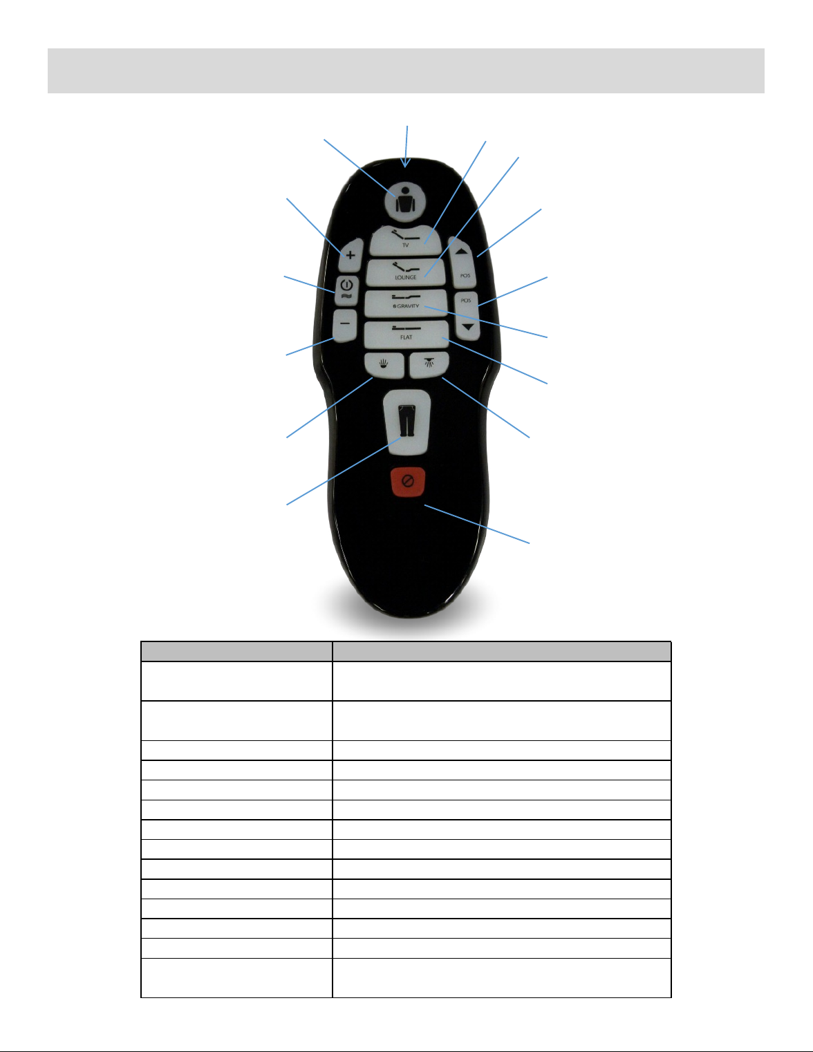
REMOTE FUNCTIONS – TS250 & TS300
14
BUTTON FUNCTION
HEAD Puts remote into Head mode, where massage and
position buttons will control head portion of base
FOOT Puts remote into Foot mode, where massage and
position buttons will control foot portion of base
POSITION UP Raises Head or Foot section of base
POSITION DOWN Lowers Head or Foot section of base
TV Pre-set TV Position
LOUNGE Pre-set Lounge Position
ZERO GRAVITY Pre-set Zero Gravity Position
FLAT One-touch Flat
MASSAGE ON/OFF Turn head/foot Massage on/off
INTENSITY UP Increases intensity of head or foot massage
INTENSITY DOWN Decreases intensity of head or foot massage
FLASHLIGHT ON/OFF Turns Remote Control flashlight on/off
UNDER BED LIGHTS ON/OFF Turns underbred lights on/off
STOP One-touch Stop will turn off massage motors and
under bed lights, as well as lower base to flat position
HEAD TV
INTENSITY
UP
MASSAGE
ON/OFF
FLASHLIGHT
ON/OFF
FOOT
LOUNGE
POSITION
UP
UNDER
BED
LIGHTS
ON/OFF
POSITION
DOWN
ZERO
GRAVITY
FLAT
FLASHLIGHT
INTENSITY
DOWN

REMOTE FUNCTIONS – TS250 & TS300
15
MEMORY FEATURE
To Enter Memory Mode
• Press/hold INTENSITY UP (+) and
POSITION UP (POS ▲) buttons at the same
time until
flashlight blinks.
• To set favorite position, adjust base to
desired position, then press/hold TV button
for 5
seconds. Position is now saved and can be
retrieved by pressing and releasing the TV
button.
To Enter Factory Preset Mode
• Press/hold INTENSITY UP (+) and
POSITION UP (POS ▲) buttons at the same
time until
flashlight blinks.
NOTES:
• TV button has different functionality
depending on what mode remote is in.
In factory
mode (no programmable memory), the
TV button moves base to the factory
preset
position. When in Memory mode, TV
button will move base to customer
programmed
position.
• Remote will retain customer
programmed position when remote
taken out of Memory
Mode.
•Remote mode can be checked by
pressing TV and LOUNGE buttons at
same time. If TV and LOUNGE
buttons are only buttons illuminated,
the remote is in Factory Preset mode.
If all buttons are illuminated, the
remote is in Memory mode.
BASIC OPERATION
To Sync to Control Box
• Press/hold TV and LOUNGE buttons at the
same time, then press/release RESET
button on
control box. Note: remote must be in
Factory Preset Mode (see Memory Feature
section below)
to sync to control box.
To Match Remotes (for synced split bed
operation from two remotes )
• Press/hold TV and LOUNGE on HJH29-A
at the same time , then press/release
RESET on
control box.
• Press/hold 0 GRAVITY and FLAT on
HJH29-B at the same time, then press
Press TV and
LOUNGE on HJH29-A at the same time
Note: remotes must be in Factory Preset
Mode (see
Memory Feature section below) to match.
To Unmatch Remotes
• Press INTENSITY DOWN (-) and
POSITION DOWN ( POS ▼) on HJH29-B
at the same time
to separate
To Operate Remote
• Press either HEAD or FOOT
• Press desired command (POS ▲/▼,
MASSAGE ON/OFF, INTENSITY +/-)
• NOTES:
• When any command button is
pressed, the HEAD or FOOT button
will light up to let
customer know what mode the
remote is in.
• The remote will stay in the most
recently used mode. For example, a
customer adjusts the head position.
After a period of time, customer
wants to adjust head. They do not
need to press HEAD button, as the
remote is still in that mode.
Customer can go directly to pressing
POS ▲/▼
16
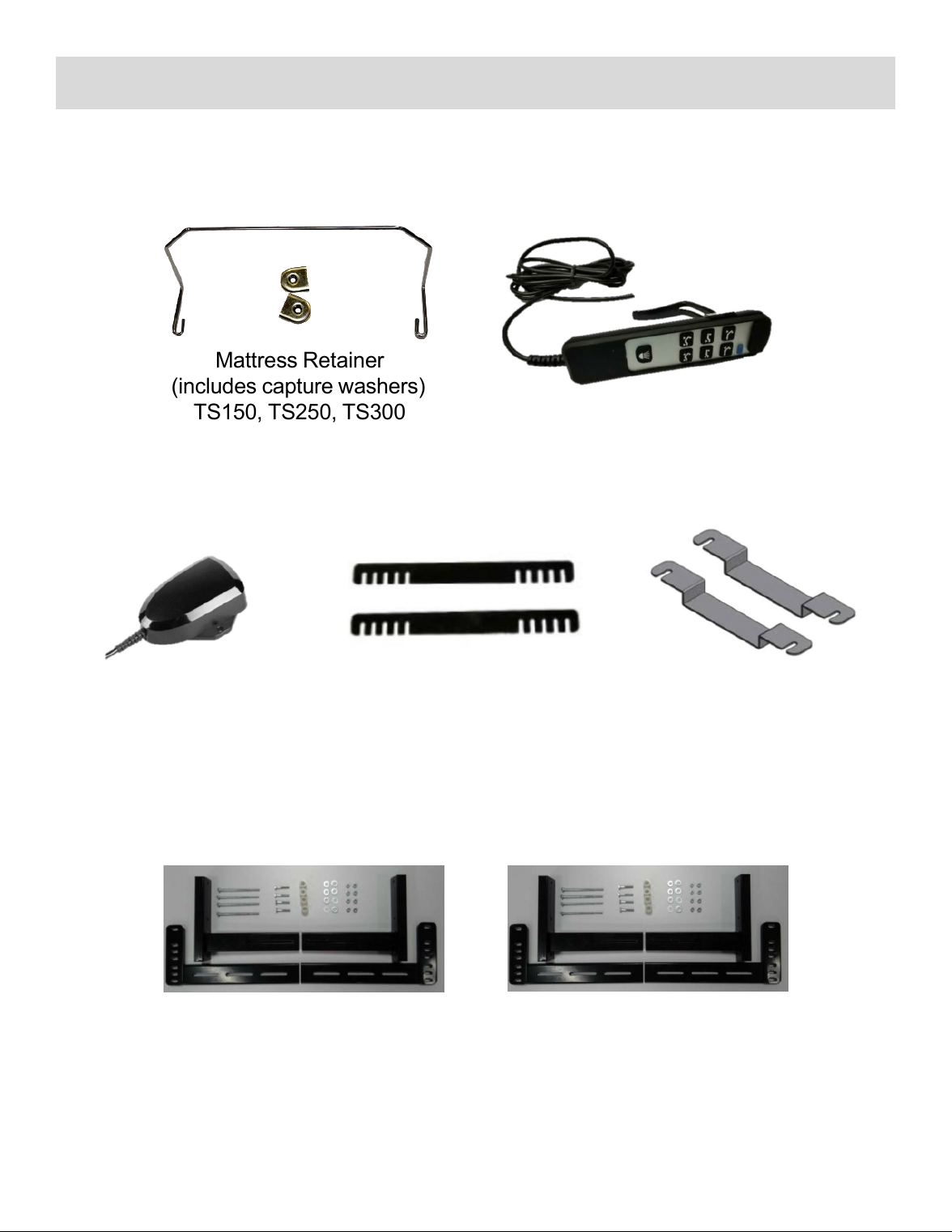
OPTIONAL ACCESSORIES
For additional information or to order, please call Customer Service at
844-433-2435 or email inquiries to info@transitionalsleep.com
Footboard Brackets –
TS150, TS250, TS300
Headboard Brackets
TS150, TS250, TS300
Split Bed
Connector
TS150
Split Bed
Connectors
TS250, TS300
Bluetooth
Receiver
TS250
Mattress Retainer
(includes capture washers)
TS150, TS250, TS300 Wired Remote
TS150

TROUBLESHOOTING
17
If your Transitional Sleep Adjustable Bed fails to operate, please review the problem you are having
and look for a solution below.
SYMPTOM SOLUTION
1. Check to make sure that your adjustable bed is plugged
into the wall outlet.
2. Your remote control may be un-synced from your
controller. Please use sync instructions on page 7 to re-sync
controller.
3. Check motor connections at controller. If loose, reattach.
Wireless remote control lights up, but is not operating
the base.
Wireless remote control does not light up. 1. Check batteries in remote to make sure that they are
installed properly.
2. Replace batteries in remote.
Massage motor noise seems excessively loud. 1. Check to make sure base is not contacting walls,
furniture, etc. that would cause noise or vibration.
2. If base is sitting on hard flooring (wood, tile, etc.), place
pieces of carpet or furniture pads under each leg.
3. If headboard bracket was installed, check to make sure
that hardware has been firmly tightened.
LED lights are not working (TS250 & TS300 only)
Bluetooth receiver is lit up but not operating the
base (TS300 only) 1. Check cable connections on Bluetooth receiver and
control box (under the base.) If loose, re-attach.
2. Re-sync Bluetooth receiver to wireless remote (page 8
in manual.)
1. Check cable connections at LED lights and controller. If
loose, re-attach.

LIMITED WARRANTY
18
HS Manufacturing, LLC (”Hickory Springs”)
ADJUSTABLE BED BASE
WARRANTY TERMS & CONDITIONS
Full 1-Year Warranty
Your adjustable bed base is warranted against defects in materials or workmanship for a period
of one year from the date of purchase by the original purchaser. This warranty is not
transferable. During this period Hickory Springs will repair or replace, at no cost to the original
purchaser, any defective part or workmanship. During this one year period Hickory Springs will bear
full responsibility for all authorized warranty related costs, including labor and transportation costs
incurred in connection with the repair or replacement of any part found to be defective.
Limited 3 Year Warranty
Beginning one year from the date of original purchase through 36 months, from said date, Hickory
Springs will replace any part on the adjustable bed base found to be defective. Note: This limited
warranty specifically excludes labor, shipping and transportation costs which will be charged to
the purchaser. This warranty is limited to the replacement of the defective electrical/mechanical
part(s).
20-Year Pro-Rated Limited Warranty
Beginning 37 months from the original purchase date through year 20 (month 240), HSM will
replace, consistent with the terms and conditions set forth herein, the adjustable base steel frame
component(s) found to be defective as follows: Purchaser shall pay 1/17 of the current
replacement cost of the defective part multiplied by the number of years after the third year from
the original purchase date. This warranty applies only to the replacement of defective frame
components. Purchaser will be responsible for labor, transportation, shipping costs, and any
installation/service fees/expenses. All warranty claims are subject to verification by HSM. This
warranty will be null and void if the product is subject to abuse, misuse, or is otherwise operated in
a manner not consistent with proper use as described in HSM’s User Manual.
Limitation of Liability
Under no circumstances shall Hickory Springs liability exceed the purchase price
paid by the original purchaser. Under no circumstances shall Hickory Springs be liable or
responsible for claims seeking special, indirect or consequential damages.
2-Year Floor Model Warranty
Your adjustable bed base floor model is warranted against defects in the electronic parts for a
period of two years from the date of purchase by the original purchaser. Subject to the limitations set
forth below, during this period Hickory Springs will replace at no cost to the original purchaser, any
defective electronic part(s). Liability is limited to the replacement of the defective electronic
part(s) ONLY, with the purchaser responsible for all service, installation and transportation costs
associated with any warranty repair.
This manual suits for next models
2
Table of contents
Popular Indoor Furnishing manuals by other brands

Politorno
Politorno Atlanta 2482 Assembly instructions

OSP Home Furnishings
OSP Home Furnishings OSP Designs BNN25 Assembly instructions

Otto
Otto LKZ 75008 Assembly instructions

highmore
highmore Raid HM-GD005-001 Assembly instructions

Whittier Wood
Whittier Wood 2072AEGSP Assembly instructions

Cooper Lighting
Cooper Lighting 605 Series Specification sheet


