Hidea EF20 User manual

EF30
EF20

The EF20 EF30 and the standard accessonries
Table
of
contents
General
information
.....
.........…
.........1
Identificatio
门
numbers
record...........1
Outboard motor serial number...
....…
1
Safety
information ............................ 1
Important
labels................................2
Warning labels .............….................2
Caution labels
.....川
........
..
.....
.
............3
Fueling instructions
......…
.........
.......3
Gasoline..
……·………..…
3
Engine oil.
………………
..
.
....3
Propeller
selection......................
......4
Sta
同斗
n-gear
protection ..............
......5
Basic
components
............................6
Main
components
…-………...............6
Fuel tank
.....…
…
……
.
,……
.6
Fuel joint .............
..
.....
..
.........… ........7
Fuel gauge.........
…..............…………
.7
Fuel tankcap
..
....... .......................... 7
Air vent screw
..
......................
....
.......7
Tiller handle .......
..
..
........................... 7
Gear shift lever.........
..
.....
......
............ 7
Throttle grip..……...….........…...........7
Throttle indicator….................…........8
Throttle friction adjuste
r..
...........
.....…
8
Enginestop lanyard switch ...............8
Engine stop button...........
....
............. 9
Manual starter handle ..............
..
....
...
9
Steering Iriction adjuster
..
................. 9
Trim tab....
..
.......................................9
Trim
rod
(tilt pin)..............................10
Tilt lock mechanism......................... 10
Tilt support bar
..
...............
....
........
...
10
Top cowling lock lever(s)
(turn type)
..
..........川…….."..…‘
....
.
.11
Warning indicator.................
....……
.11
Warning
system
.............................11
Overheat warning.....…....…..........
11
Lowoil pressure warning
….........
12
Operation
....
..
.........……
....................13
Installation ......……..…………..........13
Mounting the outboard motor........
..
13
Clamping the outboard motor….....14
Breaking
in
engine
...............口
......15
Procedure for 4-stroke models........15
Preoperation
checks
...........……
..15
Fuel
……·…
..................................15
Controls....................
………
…
………
15
Engine............
……
..................16
Checking the engine oil level
..
........16
Filling
fue
l..............................………
16
Operating
engine
....……....…
.....17
Feeding fuel (portable tank) .
...…
..17
Sta
同
ing
engine.............................
...
18
Warming
up
engine..
…........………
..19
Manual startand electric
sta
内
models .........….......... ................19
Shifting
......................……
...............19
Forward (tiller handle and remote
control models)
...……
............20
Reverse (manual tilt and hydro tilt
models).............
………
...................20
Stopping
e
门
gine.....................
.
.......21
Procedure........................................
21
Trimming
outboard
motor..
…..........
21
Adjusting trim angle
lor
manual tilt
models ..........................................22
Adjusting boat trim ..........................22
Tilting
Up
and
down
…-…-…
..........23
Procedure for tilting up
(manual tilt models)..
……
.............24
Procedure for tilting down
(manual tilt models).......................25
Cruising
in
shallow
water
...............25
Cruising in shallow waler
(manual tiltmodels).........
……
........25
Cruìsing in
other
conditions............
26
Maintenance
.................圃..............…
.27
Specificatiorls..........................
……
.27
Transpo
同
ing
and
storing
outboard
motor
............................
28
Clamp screw mounting models.......28
Storing outboard motor
..
.................28
Procedure........................... ......…..29
Lubrication
(except oil
inj~ction
models)..........30
Cleaning the outboard motor...........30
Checking painted surface
01
motor.........….................................30
Periodic
maintenance
............…
....30
Replacement parts..........................30
Maintenance chart
....…....………
.31
Maintenance chart (addilional)........32
Greasing ..............................… ...33
Cleaning and adjusting spark
plug..............
……...牛
.33
Checking fuel system.........
..
........... 34
Inspecting fuel filter
...............叫
...:....35
Cleaning fuel filter ..............
..
.…
....35
Inspecting idling speed ...................36
Changing engine oil
.….....…
........36
Checking wiring and
connecto
邸
....38
Exhaust leakage ..........
..
.................38
Water leakage.....................
..
..
........39
Engine oilleakage.
…...
….....‘
...39
Checking propeller........….........…… 39
Removing the propeller...................40
Installing the Propeller ........
..
..........40
Changing gear oil............................40
Cleaning fuel tank
..
...........…
..
.........41
Inspecting and replacing
anode(s)........ …
..
.......................42
Checking top cowling
………….4
2
Coating the boat bottom... …...........42
Trouble
Recovery
............................
44
Troubleshooting ........…..................44
Temporary
action
in
emergency
...................................47
Impact damage
.…
........................47
Starter will not operate....... ............ 47
Emergency starting engine .............48
Treatment
of
submerged
motor......
49
Procedure .......................................49
Table
of
contents

General
information
Identification
numbers
record
Outboard
motor
serial
number
The
outboard motor
ser
ial
number
is
stamped
on
the
label attached
to th
e port
side
of
the cl
amp
bracket or
the
upper
part
of
the
sw
i
ve
l bracket
Record
your
outboard motorserial
number
in
the
spaces
provided to assist you in ordering
spare
pa
川
s
from
your
dealer
or
for
reference in case your
outboa
rd
motoris sto-
len.
ZMU02638
1.
Outboard
motor
ser
ial
number
loc
ation
& Safety
information
• Beforemounting or operating the outboard
motor, read this entire manua
l.
Reading it
should give you an understanding of the
motor and its operation.
• Before operating the boat, read any own-
er's or operator's manuals supp
li
ed with it
and all labels. Be sure you understand
each item before operating
•
00
not overpower the boat with this out-
board moto
r.
Overpowering the boatcould
result
in
loss ofcontrol. The rated powerof
the outboard should be equal to or less
than the rated horsepower capacity of the
boa
t.
If the rated horsepower capacity
of
the boat is unknown, consult the dealer
or
boat manufacturer.
•
00
not modify the outboard. Modifications
could make the motor unfit
or
unsafe to
use
• Incorrect propeller selection and incorrect
use may not only cause engine damage,
but al
so
adversely affectfuel consumption.
Consult your dealer for correct use.
• Neveroperate afterdrinking alcohol
or
tak-
ing drugs. About 50% of a
ll
boating fatali-
ties involve intoxication
• Have an approved personal flotation de-
vice (
PF
O)
on board for every occupan
t.
It
is a good idea to wear a
PFO
whenever
boating. At a minimum, childr
en
and non-
sw
immers should always wear PFOs, and
everyone should wear PFOs when there
are potentially hazardous boating condi-
tions
• Gasoline is highly flammable, and its va-
pors are flammable and explosive. Handle
and store gasoline carefull
y.
Make sure
there are no gas fumes
or
leaking fuel be-
fore
s
t
a
同
in
g
the engine
• This product
em
its exhaust gases
wh
i
ch
contain carbon monoxide, a colorless,
。
dorless
gaswhich may cause brain dam-
age
or
death when inhaled. Symptoms in-
clude nausea, dizziness, and drowsiness
Keep cockpit and cabin areas well ventilat-
ed.
Avoid blocking exhaust outlets
• Check throttle, shift, and steering for prop
er operation before starting the engine.
• Atlach the engine stop switch lanyard to a
secure place
on
your clothing, or your arm
or leg while operating. If you accidentally
leave the helm, the lanyard will pull from
Ihe swilch, stopping the engine.
• Know Ihe marine laws and regulations
where you will beboating -and obey them
• Stay informed aboul the wealhe
r.
Check
wealher forecasts before boating. Avoid
boating in hazardous weather.
• Tell someone where you are going: leave
a Float Plan with a responsible person. Be
sure
10
cancellhe Float Plan when you re-
turn
• Use common sense and good judgment
when boating. Know your abililies, and be
sure you understand how your boat han-
dles lindérthe different boating conditions
you may encounte
r.
Operate within your
limits, and the limils
ofyour
boa
t.
Always
operate at safe speeds,and keep a careful
watch for obslacles and olherIraffic.
• Always watch carefuUy for swimmers dur-
ing the engine operation.
• Slay away from swimming areas.
• When a swimmer is in the water near you
shift inlo neulral and shut offIhe engine.
•
00
not iIIegally discard empty containers
used
10
replace or replenish
oi
l.
For the
correct processing
of
empty
containe
邸,
consult the dealer where.you purchased
the oil.
• When replacing oils used to lubricate the
product (engine
or
gear oil), be sure
t
口
wipe away anyspilt
oi
l.
Neverpouroil wilh-
out using a funnel
or
similardevice. If nec-
essary, verify Ihe necessary replacemenl
General information
procedure with the dealer.
• Neverillegallydiscard (dump) the product
re
∞
mmends
∞
nsulting
the dealer
on discarding the produc
t.
Important
labels
Warning
labels
Label
,?‘
'1"!':I~II~[
e'I
•
Be
sure
shift
control
is
in
neutral before
starting
engine. (except 2HP)
• Do
not
touch
or
remove electrical
pa
叫
S
when
starting
or
during
operation.
• Keep hands,
hair
,
and
clothes
away
from
flywheel
and
other
rotating parts
while
engine
is
running_
Label
,【帽
•
This
engine
is
equipped
with
a neutral
starting
device.
• The
engine
will
not
start
unless
the
shift
control
is
in
neutral
position.
2

General
information
Caution
labels
Label
腾腾腾;
Transport
and
store
the
engine
only
as
shown.
Otherwise
,
engine
damage
could
result
from
Leaking oil.
Fueling
instructions
,
1
‘
,
'I'/!':I~
11
H
帽
GASO
Ll
NE
AND ITS VAPORS ARE HIGH-
LY FLAMMABLE AND EXPLOSIVE!
•
Do
not
smoke
when
refueling,and keep
away
from
sparks
,
Ilames
,
or
other
sources
of
ignition.
•
Stop
engine
before
refueling.
• Refuel
in
a well-ventilated area. Refuel
portablefuel
tanks
ofl
the
boat.
• Take care
not
to
spill
gasoline.
If
gaso-
line
spills
,
wipe
it
up
immediately
with
dry
rags.
• Do
not
overfill
the
fuel
tank
,
• Tighten
the
filler
cap
securely
after re-
fueling.
•
If
you
should
swallow
some
gasoline,
inhale a
lot
of
gasoline
vapor
,
or
get
gasoline
in
your
eyes,
get
immediate
3
medical attention,
•
11
any
gasoline
spills
onto
your
skin
,
im-
mediately wash
with
soap
and
water.
Change
clothing
if
gasoline
spills
on
i
t.
•
Touch
the
fuel
nozzle
to
the
filler
open-
i
ng
or
funnel
to
help prevent
electro
圃
static
sparks.
装翩翩
Use
only
new
clean
gasoline
which
has
been
stored
in
clean
conlainers
and
is
not
contaminated
with
water
or
foreign
mat-
ter.
Gasoline
Recommended gasoline
Regular unleaded gasoline
1I
knocking
or
pinging occurs, use a
di
仔
erenl
brand
01
gasoline or premium unleaded fuel
1I
unleaded gasoline is not available, then
premium gasoline can be used, If leaded
gasoline is usually used, engine valves and
related partsshould
be
inspected aflerevery
300 hours
01
operation.
Engine
oil
Recommended engine oil:
4-stroke moloroil wilh a combination
01
lhe
following SAE and API oilclassi-
lications
Engine oil type SAE:
1
OW-30
or
10W-40
Engine oil grade API
SE,SF,
SG
,SH,SJ,SL
Engine oil quantity (excluding oil lilter):
1.7 L (1.80 US qt) (1.50 Imp.qt)
NOTE:
1I
Ihe recommended engine oil grades are
not available, select
an
alternalive Irom
Ihe
lollowing chart according to the average
temperalures in your area,
SAE
API
-4
14
32
50
68
86
104
122'F
-20 -10
D
10
20
30
40
511ß
K
10W-30
卫
SE
SF
:
ISG
仆
<:
10W
-4
0
:::>
:
ISH
: ISJ
k'
50
30
~
: : ISL
I
15W
-
40
二辛:
SH
:匾匣巫二丰
SJ
SL
翩翩
;
AII 4-stroke enginesare
shipped
from
the
factory
without
engine oi
l.
Propeller
selection
The performance
01
youroulboard motor will
be
criticallyaffected by your choice
01
propel-
ler, as
an
incorrect choice could
adversely
affect performance and could also seriously
damage the moto
r.
Engine speed depends
on
the propeUer size and boat load.
1I
engine
General
information
speed is
100
high or
100
low for good engine
perlormance, this
wiU
have
an
adverse effect
on
the engine
These outboard molors are litted with pro-
pellers chosen
10
pe
斤。rm
well over a range
01
applications,butthere may be uses where
a propeller with a different pitch would be
more appropriate. For a greater operating
load, a smaller-pitch propeller is more suit-
able as it enables the correct engine speed
to be maintained. Conversely, a larger-pitch
propeller is more suitable
lor
a smaller oper-
ating load.
The dealers stock a range ofpropellers,
and can advise you and install a propelleron
your outboard that is besl suiled to your ap-
plication.
1.
Propeller
diameter
in
inches
2.
Pr
o
peller
pitch
in
inches
3.
Type
01
p
盯
p
e
ller
(propeller
mark)
NOTE:
Selecta propellerwhich will allow the
e门
glne
to reach the middle
or
upper half
01
the oper-
ating range at lull throttle with the maximum
boat load. If operating conditions such as
lightboat loadsthen allow the engine r/min to
ris
e above the maximum
recommEmded
range, reduce the throttle setting to maintain
the engine
in
the properoperating range.
4
EF20
EF30

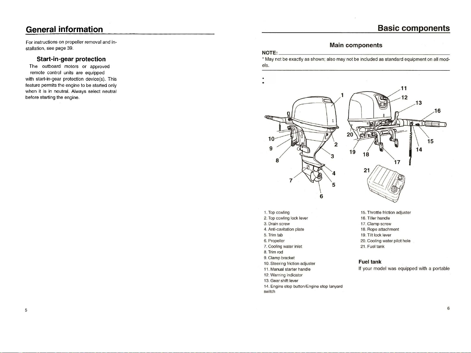
Basiccomponents
fuel tank, its funclion
is
as follows.
r
,,,,
"'il~
,,
~[1
幅
The1uel tank supplied
with
th
ls engine Is
its dedicated fuel reservoir and
must
not
be
usedasa fuel storage container. Com-
merclal usersshould
conform
to
relevant
IIcensing
or
approval
authority
reguia-
tions.
1.
Fuel
join
t
2.Fu
el
g
auge
3.
Fue
lla
nk
cap
4.
Air
v
ent
screw
Fuel
joint
了
his
joint
is
used to connecl Ihe
fu
e
llin
e
Fuel
gaug
.e
This gauge islocated on either the fuel tank
cap oron the fuel
jo
intbase. 1I shows the ap-
proximale amount
01
fuel remaining in the
tank
Fueltank
cap
This cap seals the
lu
el tank.When removed,
Ihetankcanbelilledwi
lh
lue
l.
To removethe
cap, turn it
co
unterciockwise
Air
vent
screw
This screw is on the luel tank cap. To loosen
the screw, turn it counterclockwise.
7
Tiller
handle
Tochange direction, mo
ve
the tiller handle to
the left or right as necessary
到
U
Throttle
indicator
The luel consumption curve
on
the throttle
indicator shows the relative amount
01
luel
consumed
lor
each Ihrottle posilion. Choose
the setting that olfers Ihe best performance
and luel economy
lor
the desired operation.
Gear
shift
lever
Pulling the gear shift lev
er
to
wa
rds you puts
the engine in lorward gear so that Ihe boat
mo
ves ahead. Pushing the lever away Irom
you puts the engine in reverse gear so th
al
the boal moves aslern. 1
1.
Thr
o
ttle
indi
ca
tor
1.
Forw
ard
宇
"
2.
Neut
ral"N"
3.R
ev
erse
"R"
Throttle
friction
adjuster
A Iriction device provides adjustable resis-
tance to movement
01
the throttle grip
or
the
remote controllever, and can be set accord-
ing to operatorprelerence.
To increase resistance, turn the adjuster
clockwise. To decrease resistance, turn the
adjuster counlerclockwise
Throtlle
grip
The throlt
le
grip is on the liller handle. Turn
the grip counle
rcl
ockwise
10
increase speed
and clockw
is
e 10 decrease speed
,
1
‘
""!':I~II~r
e'l
Do
not
overtighten
the
friction
adjuster
.
If
Basic
components
there
is
too
much
resistance,
it
could
be
difficult
to
move
throttle
lever
or
grip
,
which
could
result
in
an
acciden
t.
When constant speed is desired, lighten the
adjuster to maintain the desired throttle set-
ting
Engine
stop
lanyard
switch
The lock plate must be attached
10
the en-
gine stop switch
lor
the engine to
run
. The
lanyard should be attached to asecure place
on the operator's clothing, or arm
or
¥
leg
Should the operator lall overboard or leave
the helm, the lanyard will pull out the lock
plate, stopping ignition to the engine. This
will prevent the boat Irom running away un-
derpower
,?‘
.""!':I~II~
【帽
• Attach the
engine
stop
switch
lanyard
to
a secure place
on
your
clothing
,
or
your
arm
or
leg
while
operating.
• Do
not
attach
the lanyard
to
clothing
that
could
tear
loose.
00
not
route
the
lanyard where
it
could
become entan-
gled,
preventing
it
from
functioning.
•
Avoid
accidentally
pulling
the la,nyard
during
normal
operation.
Loss
of
en-
gine
power
means
the
loss
01
most
steering
contro
l.
Also
,
without
engine
power
,
the
boat
could
slow
rapidly.This
8

Basic components
could
cause people and objects
in
the
boat
to
be thrown forward.
NOTE
:
The engine ca
nn
ot be started with t
he
lock
plate
re
moved.
1.
Lanyard
2.L
∞
k
pl
ate
Engine
stop
button
To open the ignition
ci
rcuit a
nd
stop the en-
gine, push this button.
Manual
starter
handle
To
sta
rt
the engine, first gently pull the h
an
-
dle out until resistance is fel
t.
Fromthat posi-
ti
on, then pull
th
e handle straig
ht
out quic
kl
y
tocrank t
he
engine.
9
St
回
ring
friction
adjuster
A friction device provides adjusta
bl
e resis-
tance tothesteering mechanism, and can be
set according to operatorpreference. An ad-
justing screw orbolt is located on the swivel
bracke
t.
,
1
‘
,
'I'I
!
1:mm
帽
00
not
overt
ightenthe
friction
adjuster.
If
ther
e is t
oo
much
resistance,
it
could
be
dif
f
icult
to
steer
,
which
could
result
in
an
accident.
Trim
tab
The trim tab should be
a
啕
us
t
ed
so that t
he
steering control can be
tu
med to either the
right or left by applying the same amount 01
lorce.
,?‘,
'1"
!1:1~
1I~【帽
An
improperly
adj
uste
d
trim
tab could
cause
difficult
st
e
ering
. A
lw
ays
tes
t run
aft
er
the
trim
tab
has
been
ins
talled
or
re-
placed
to
be sure steering
is
correc
t.
Be
sure
yo
u have tightened
the
bolt
a
ft
er
ad-
iusting
the
trim
tab.
1I
th
e boat tends to veer the left
(po
叫
s
i
de
)
,
tum the trim tab rear end to the port side "
A"
in the ligure.
1I the boat tends
to
veer the right (starboard
side), tum the trim tab end to the starboard
side"8" in the figure
1.
T
ri
mt
ab
2. 8olt
Tr
im
r
od
(til
t pi
n)
T
he
posi
ti
on
of the trim rod determines the
minimum trim angle ofthe outboard motor in
re
lat
ion
to the transom.
Basic components
1.
Tilt
lock
l
ever
To lockit,set the tilt lock leverin the lock
po
胃
sition. To
re
lease, push the tilt lock lever in
the
re
lease position
Ti
lt
support
bar
Thetiltsupportbarkeepsthe outboard
mo
to
r
in
the tilted
up
position.
10
Basic
components
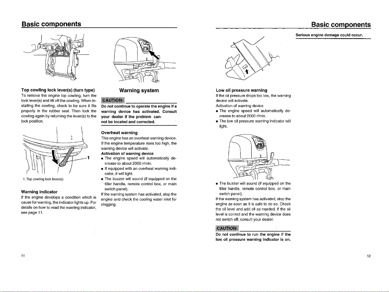
Top
cowling
lock
lever(s)
(turn
type)
To remove the engine top cowling, turn the
locklever(s) and liftoffthe cowling. When in-
st
剖
ling
the cowling, check to be sure it fits
properly in the rubber sea
l.
Then lock the
cowling again
by
returning the lever(s) to the
lockposition.
1.
Top
cowling
lock
l
ever(s)
Warning
indicator
If the engine develops a condition which is
causeforwarning,the indicatorlights up.For
detailson how to read the warning indicator,
see page
11.
11
Warning
system
Low
oil
pressure
warning
1I
the oil pressure drops too low, the warning
device will activale.
Activation
01
warning device
• The engine speed will automatically de-
crease to aboul
2000
旷
mm.
• The low oil pressure warning indicalor will
lighl.
嫌腾
腾
接
00
not
continue
to
operate
the
engine
if
a
warning
device
has
activated.
Consult
your
dealer
if
the
problem
can-
not
be
located
and
corrected.
Overheat
warning
Thisengine has an overheatwarning device.
1I
the engine temperalure rises too high, Ihe
warning device will aclivale.
Activation
of
warning
device
1 • The engine speed will automalically de-
crease
10
aboul2000 r/min.
• If equipped wilh an overheal warning indi-
calor, it willligh
l.
• The buzzer will sound (if equipped on the
till
er
hand
怡,
remote control box,
or
main
switch panel).
1I
the warning system has activated, stop the
engine and check the cooling water inlel for
clogging.
• The buzzer will sound (il equipped on the
tiller handle, remote control box, or main
switch panel)
1I
the warning system has activated,stop the
engine as soon as it
is
safe to do so. Check
the oil level and add oil as needed.
1I
the oil
level is correct and Ihe warning device does
nol swilch
011
, consult your deale
r.
e
1n
uO
Hs
a-VE
no
--E&E
‘-
qHa
nc
ed
awnH
hi
---nB
n-m
un
,
-VE
bm
ee
』
r
mu
;15
谧黯叫地
挡回慰。阿
摇撼
cp
it-
;;
倘…附
mo
m
蛐翩翩
DW
淄燃
nub
Basic
components
Serious
engine
damage
could
occur.
12
Operation
Installation
Incorrect
engine
height
or
obstructions
to
smooth
water
flow
(such
as
the
design
or
condition
of
the
boat
,
or
accessories
such
as
transo
l'!l ladders
or
depth
finder
transducers)
can create
airborne
water
spray while the
boat
is
cruising.
Severe
engine damage
may
result
if
the
motor
is
operated
continuously
in
the
presence
of
airborne
water spray.
NOTE
:
During water testing check the buoyancy
01
the boat, at rest, with
it
s ma
xi
mum load.
Check that the static wat
er
level on the ex-
haust housing is low enough to prevent wa-
ter entry into the powerhead, when
wa
ter
rises due to waves when the outboard is not
runnlng.
Mounting
the
outboard
motor
,
1
‘ljlI!,
mll~
【帽
• Overpowering a
boat
could
cause se-
vere Instabliity.
00
not
install an
out-
board
motor
with
more
horsepower
than
the
maximum
rating
on
the
capac-
ity
plate
of
the
boat.
If
the
boat
does
not
have a capacity plate,
consult
the
boat
manufacturer
.
• The
information
presented
in
this
sec-
tion
is
intended
as
reference only.
It
is
not
possible
to
provide
complete
in-
structions
for
every
possible
boat
and
motor
combination. Proper
mounting
depends
in
part
on
experience
and
the
13
specific
boat
and
motor
combination.
,
"5'jjjij~
lI~【帽
Improper
mounting
of
the
outboard
mo-
tor
could
result
ín hazardous
conditions
such
as
poor
handling
,
loss
of
cont
r
ol
,
or
fire
hazards. Observe
the
following
:
• Forpermanently
mounted
models
,
your
dealer
or
other
person
experienced
in
proper
rigging
should
mount
the
motor
.
if
you
are
mounting
the
motor
yourself
,
you
should
be
trained
by
an experi-
enced
person
.
• For
portable
models
,
your
dealer
or
oth-
er
person
experienced
in
pr
oper
out-
board
motor
mounting
should
show
you
how
to
mount
your
motor.
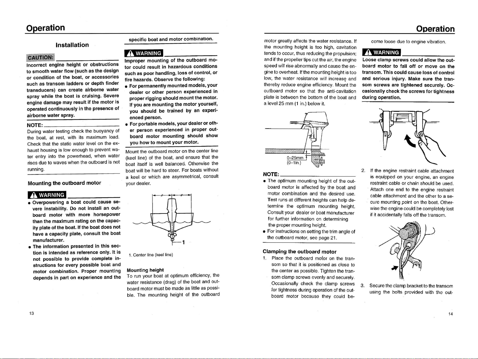
Mounl
lhe
outboard mot
or
on the center line
(keel line)
01
the boat, and
e
n5U
陀
t
ha
t
lhe
boat itself is well balanced. Otherwise the
boal
wi
ll
be
hard to steer. For boats without
a keel
or
which are asymmetrical, con
su
lt
your deal
er
1.
Cen
terl
ine
(keel
Un
e)
Mountlng
height
To run your boat at optimum efficiency, the
water resislance (drag) 01the boat and out-
board motormustbe made às little as
poss卜
bl
e.
The mounting height
01
the outboa
rd
motor
gr
eatly affects the water resistance. If
the mounting height is too high, cavitalion
tends
10
occur, Ihus reducing
lhe
propulsion;
and ifthe propellerlips cutIheair,the engine
speed will rise abnormally and cause the en-
gine to overhea
t.
1I the mounting heightis100
low, the waler resistance will inc
re
as!?
and
Ihereby reduce engine efficien
cy
. Mount the
oulboard motor
50
lha
t lhe anti-cavilalion
plale is belween the
bo
ttom
01
Ihe boat and
a le
ve
l 25 mm (1 in.) below i
t.
NOTE:
• The optimum mounting height 01the oul-
board molor is affected by Ihe boal and
motor combination and the desired'
U5
e
Test runs at different heights can help de-
termine Ihe optimum mounling height
Consult your dealeror boat manulacturer
for lurther inlormation on determining
the p
ro
per mounting height.
• F
or
instructio
ns
on setting IheIrim angle
01
the outboard mot
or
, see page 21.
Clamping
the
outboard
motor
1. Place the outboard molor on the tran-
som so that it is positioned as close to
the center as possible. Tighlen the tran-
som clamp screws evenly and securely.
Occasiona
ll
y check the clamp screws
lo
r tightness
du
ri
ng operation 01the oul-
boa
rd
motor because Ihey could be-
Qperation
come loose dueto engine vibration.
,?‘,
""~':J~lhH
帽
Loose
clamp
screws
could
allow
the
out-
board
motor
to
fall
oft
or
move
on
the
transom.
This
could
cause
loss
01
control
and
serious
injury. Make
sure
the tran-
som
screws
are ti
ghtened
securely. Oc-
caslonally
check
the
screws
for
tightness
during
operation.
2. 1I Ihe engine restra
int
cable attachment
is equipped on your engine, an engine
re5traint cable
or
chain should
be
use
d.
Attach one end
10
the engine restrai
nl
cable attachment and Ihe other
10
a
se-
cure mounting point on lhe boa
t.
Other-
wisethe engine could be complelely lost
il
it
a
∞
i
de
ntally
falls off the transom.
3. Securethe clampbrackeltoIhe
tr
ansom
using the bolts
pr
ov
ided wi
lh
the out-
14
QPeration
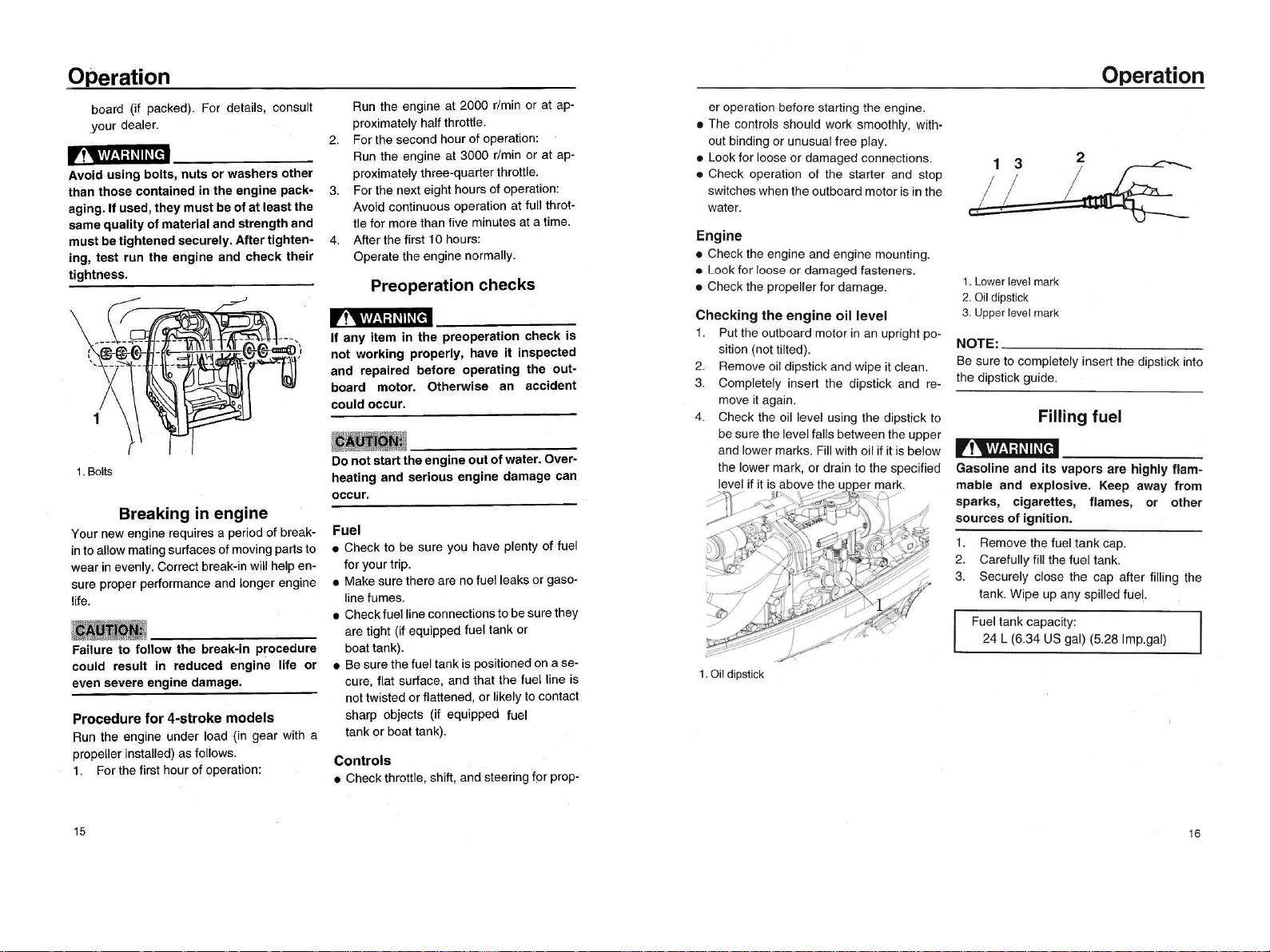
board (il packed). For details, consult
your dealer
,?‘
.'1'
1!
1
剖
~lhH
帽
Avoid
using
bolts
,
nuts
or
washers other
than
those
contained
in
the
engine pack-
aging.11 used,
they
must
be
01
at
leastthe
same
quality
01
material and strengthand
must
betightened securely.After tighten-
ing
,
test
run
the engine and
check
their
tightness.
1.
Bolts
Breaking
in
engine
Your 门
ew
engine requires a period
01
break.
in to allowmating surfaces
01
moving
pa
民
sto
wear
in
evenly. Correct break-in will help en-
sure proper
pe
斤。
rmance
and longer engine
lile.
翻腾腾意
Failure
to
follow
the
break-in procedure
could
result
in
reduced engine
lile
or
even severe engine damage.
Procedure
for
4-stroke
models
Run
the engine under load (in gear with a
propeller installed)
as
lollows
1.
For the lirst hour
01
operation:
15
Run
the engine at 2000 r/min or at ap-
proximately hallthrottle.
2.
For the second hour
of
operation:
Run
the engine at 3000 r/min or at ap-
proximately three-quarterthrottle.
3. For the next eight hours of operation:
Avoid continuous operation at luli throt-
tle for more than five minutes at a time.
4.
After the first 10 hours:
Operate the engine normaliy.
Preoperation
checks
,!'-'i!l唱
I~II~[
帽
1I
any
item
in
the
preoperation
check
is
not
working
properly
, have
it
inspected
and repaired
belore
operating
the
out-
board motor. Otherwise an accident
could
occur.
楼翻数通意
00
notsta
民
the
engine
out
01
water. Over-
heating and
serious
engine damage can
occur.
Fuel
• Check to be sure you have plenty
01
luel
lor
your trip.
• Make sure there are noluelleaks or gaso-
linelumes
• Checkluellineconnectionsto be sure they
are tight (il equipped fuel tank or
boat tank).
•
Be
sure the fuel tank is positioned on a se-
cure, Ilat surface, and that the luel line is
not twisted orIlattened, orlikely to contact
sharp objects (if equipped luel
tank orboat tank).
Controls
• Check throttle, shift, andsteering
lor
prop-
er
operation before starting the engine
• The conlrols should work Smoolhly, wilh-
out binding orunusual free play
• Look for loose or damaged connections.
• Check operation
01
the starter and stop
switcheswhen the outboard motoris in the
wa
ter.
Engine
• Check the engine and engine mounting.
• Look for loose
or
damaged fasteners.
• Checkthe propellerfor damage.
Checking
the
engine
oil
level
1. Put the outboard motor
in
an upright po-
sition (nol tilted).
2.
Remove oil dipstick and wipe it clean.
3. Completely insert the dipstick
and
re-
move
it
again
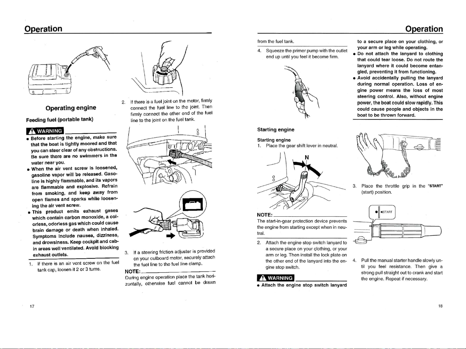
4. Check the oil level using the dipstick to
besure the level falls between the upper
and
l
ower
marks. Fill with o
il
if it is below
the lower
mark
,
or
drain
10
Ihe specified
level if
it
is
above
the upper mark
y
号
---
II
'
~
‘--
---
~
-.
'
/
1.
Oil
dipstick
Operation
1.
Lower
lev
el
mark
2.
Oil
dipstick
3.
Upper
level
mark
NOTE:
Be
sure to completely insert the dipstick into
the dipstick guide.
Filling
fuel
,帽
Gasoline
and
its
vapors are
highly
flam-
mable and explosive. Keep away
Irom
sparks
, cigarettes, flames,
or
other
sources
01
ignition.
1.
Remove the luel tankcap
2. Carelully lill the
lu
el tank.
3.
Securely close the cap after lilling Ihe
tank. Wipe up any spilied lue!
Fuel tank capacity:
24 L (6.34
US
gal) (5.28 Imp.gal)
16
Operation
Operatingengine
Feeding
fuel
(portable
tank)
,?‘
~"'~1:1"
1I1H帽
•
Before
starting
the
engine
,
make
sure
1hat 1he
boat
is
tightly
moored
and
怡、
at
you
can
steer
clear
of
any
obstruct
i
ons.
Be
sure
there
are no
s
硝
immers
in
the
water
near
you.
• When
the
air
vent
screw
is
loosened,
g8soline
vapor
will
be released. Gaso-
line
is
highly
flamm
自
ble
,
and
its
vapors
are flammable
and
explosive
. Refrain
from
smoking
,
and
keep
away
from
open
flames
and
sparks
while
1005en-
ing
the
alr
vent
screw
.
•
This
product
emits
exhau5t
gases
which
contain
carbon
monoxide
,a
col-
orless
,
odorl
e
ss
gas
which
could
cause
brain
damage
or
death
when inhaled.
Symptoms
include
nausea, dizzi
ness
,
and
dro
峭
Iness.
K
锦
P
cockpit
and
cab-
in
areas well ventilated.
Avold
blocking
exhaust
outlets.
1.
1I
there
恪
an
air vent scr
ew
on the fuel
tank cap, loosen it 2 or 3tu
rn
s.
17
2.
1I
Ihere is a luel joint on Ihe molor,lirmly
connect lhe
lu
el line 10 Ihe join
t.
Then
lirmiy
co
们
necl
the olher end 01Ihe luel
line 10 the joinl on Ihe
fu
eltank.
3.
lf
a steering
Iri
ctio
r、
adjuste
r
is provided
on your o
ulb
oard molor,securely a
ll
ach
the fue
llin
e to
Ih
e fuel iine clamp.
NOTE:
During engine operalion place
th
e tank hori-
zonlally, olherwi
se
fu
el cannol be drawn
from the fuel tank
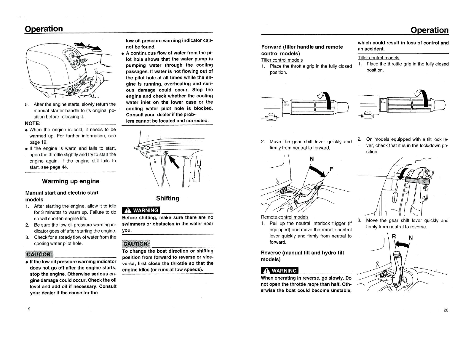
4. Squeeze the primerpump withthe outlet
end up untii you feel
it
become lirm.
Starting
engine
Starting
engine
1. Place Ihe gear s
hilll
ever
in
neulral.
NOTE:
The
sla
rt-in-gear proleclion device prevenls
Ihe engine from slarting excepl when in neu-
Ira
l.
2. Attach
lhe
engine slop swilch lanyard 10
a secure piace on your çlothing. or your
arm
or
leg. Then inslalllhe lock plale on
Ihe o
lh
er end
01
the lanyard inlo the en-
gine slop sw
il
ch.
,
1
‘币,主,
':I~II~[
帽
• Attach the engine
stop
switch
lanyard
Operation
to
a
secure
place
on
your
clothing
,
or
your
arm
or
leg
while
operating.
•
00
n01 attach
the
lanyard
to
clothing
that
could
tear
loose.
00
not
route the
lanyard
where
it
could
become entan-
gled
,
preventing
it
from
functioning.
•
Avoid
accidentally
puliing
the lanyard
during
normal
operation.
Loss
of
en-
gine
power
means
the
loss
of
most
steering
contro
l.
Also
,
without
engine
power
,the
boat
could
slow
rapidly. This
could
cause
people
and
objects
in
the
boat
to
be
thrown
forward.
3. Place Ihe Ihrottle grip in Ihe "
START
"
(s
t
a叫
)
position.
4. Pull the manualslarter handleslowly un-
lil you leel resislance. Then
ωve
a
slrong pull straight ou
ll
o crank and slart
Ihe eng
in
e. Repeal if necessary
18
Operél
tion
5.
A
ft
er Ihe engine slarts, slowly relu
rn
Ih
e
manual slarler handle 10
il
s
or
iginal po-
silion belore releasing
il
NOTE:
•
Wh
en
Ih
e engine is cold,
il
n
ee
ds 10 be
warmed up. For lurth
er
inlorma
li
on, see
page 1
9.
• If Ihe engine is wa
rm
and lails
10
slart,
open
Ih
eIhrottle slightly andI
ry
10 sla
rt
Ihe
engine again. If Ihe engine slill lails 10
s
l
a
川
,
see
page 44
Warming Up engine
Manual
start
and
electric
start
models
1. Aft
er
sla
rti
ng
Ih
e engine, allow il 10 idle
lor 3 minules 10 warm up. Failure 10 do
sowill sho
rt
en engine lil
e.
2. Be sure Ihe low
oi
l pressure
wa
rning in-
dicalor goes 0
11
afterslartingIhe eng
in
e
3. Checkl
or
a
sl
eady
fl
ow 01walerIromIhe
cooling waler pilol hol
e.
激鳞
剿
罢
•
If
the
low
oil
pressure
warning
indicator
does
not
go
off
after
the
engine
starts
,
stop
the
engine
.
Otherwise
serious
en-
gine
damage
could
occur.
Checkthe
oil
level
and
add
oil
if
necessary.
Consult
your
dealer
if
the cause
for
the
19
low
oil
pressure
warning
ind
icator can-
not
be
found.
• A
continuous
flow
of
water
from
the
pi-
lot
hole
shows
that
the
water
pump
is
pumping
water
through
the
cooling
passages.
If
water
is
not
flowing
out
of
the
pilot
hole
at
all
times
while
the
en-
gine
is
running
,
overheating
and
seri-
ous
damage
could
occur
.
Stop
the
engine
and
check
whether
the
cool
i
ng
water
inlet
on
the
lower
case
or
the
cooling
water
pilot
hole
is
blocked
.
Consult
your
dealer
if
the
prob-
lem
cannot
be
located
and
corrected.
Forward
(tiller
handle
and
remote
control
models)
Tiller conlrol models
1.
Pl
ace Ihe Ihrottle grip in Ihe lully closed
P
臼
Ili
o n
Operation
which
could
result
in
loss
of
control
and
an accident.
Tiller conlrol models
1.
Pl
ace
th
e throttle grip in
Ih
e fully closed
position
2.
Move Ihe gear shill lever quickly and
2.
On
m
od
e.
I
S.
.
e
~ui
pp
e
d
w
it~
a
:i
.
lI.
lock le-
lirmly
Ir
om neutral 10 lorwa
rd.
v
凹,
check Ihat it is in Ihe
10
c
kJ
down po-
sition
Shifting
,,
V/
!1
ilm~
【帽
Remote control models
1. Pull up the ne
ul
r
al
inlerlock Irigger (il
eq
ui
pped) and move Ihe remole control
lev
er
quic
kl
y and lirmly Irom ne
ulr
al 10
lorward
oW
nE
。
5
en
vE
a
创
咀
@ν
刽
创
w
山山川
e
41
』
H
et
W.m
怠-
s
ee
b
民UA
啤卸
mu
·
冒‘
『
S
'
hu
go
n
ι.
,,.
"uo
u
m
宫
S
创
em
创
mL
fiu
ewα
BSY
嫌翻腾
To
change
the
boat
direction
or
shifting
position
from
forward
to
reverse
or
vice-
versa,
first
close
the
throttle
so
that
the
engine
idles
(or
runs
at
low
speeds).
Reverse
(manual
tilt
an~
hydro
tilt
models)
,?‘
'1'1
!
1:1~
1I~[帽
When operating
in
reverse,
go
slowly
.
00
not
open
the
throttle
more
than
half
.
Oth-
erwise
the
boat
could
become
unstable
,
3. Move Ihe gear shift lever quickly and
lirmly Irom neulral
10
reverse.
20

Operation
Remote control models
1. Checkthat the tilt lock leveris in the lock
positíon.
2.
Pull up the neutral inte
rl
ock trigger (if
equipped) and move the remote control
lever quickly and firmly
fr
om neutral to
reverse.
Stopping engine
Before stopping
th
e engine, first let it cool oft
for a few minutes at idle or low speed. Stop-
3.
Disconnect the
fu
el line if you are using
pi
ng the engine immediately after operating an external
fu
el tank.
at high speed is not recommended.
Procedure
1. Push and hold the engine st
op
button
until the engine comes to a complete
stop
2.
After stopping the engine,tighten the aír
vent screw on the fuel tank cap and set
the fuel cock lever or
kn
ob to the closed
position, ife
qu
ipped.
21
NOTE
:
If the outboard motor is equipped with anen-
ginestop switch lanya
rd
, theengine can also
be
stopped bypulling the lanyard and remov-
ing the lock plate from the eng
in
e stop
switch
Trimming
outboard
motor
The trim angle of the outboard motor helps
determine the position of the bowof the boat
in the wate
r.
Correct t
ri
m angle will help im-
prove
pe
斤
。rm
a
n
ce
and fuel economy while
r
ed
ucing strain on the eng
in
e. Correct trim
an
gle depends upon the combina
ti
on of
boat, engine, and propelle
r.
Correct t
rim
is
also affected by variables such asthe load in
the boat, sea conditions, and running speed
,,
..
协
1:1~
1I~【帽
Excessive
trim
for
the
operating
condi-
tions
(either
trim
up
or
trim
down)
can
cause
boat
instability
and
can make
steering the
boat
more
difficul
t.
This
in-
creases
the
possibility
of
an accideh
t.
If
the
boat
begins
to
feel unstable
or
is
hard
to
steer,
slow
down
and/or
readjust
the
trim
angle.
」
γ
二
1.T
ri
m
ope
ra
tin
g
angle
Adjusting
trim
angle
for
manual
tilt
models
There a
re
4 or 5 holes pro
vi
ded
in
the ciamp
bracket to adjust the outboard motortrim an-
gl
e.
1.
Stop
th
e engine.
2.
Remove the trim
rod
from the clamp
Operation
br
acket while slightly tilting the outboa
rd
motor up.
1. Trim
rod
3.
Reposition the rod
in
the desired hol
e.
To ra
is
e
th
e b
ow
("trim-ou
t"
),
move the
ro
d
away from the transom
To lowerthe bow ("trim-in"), move the rodto-
wa
rd the tran
so
m.
Make test
run
s with the trim set to different
angles to find
tn
e p
os
ition that wo
rk
s best for
yo
urboat and operating conditions
,?‘
.'I'H:I~II~
【帽
•
Stop
the
engine
before
adjusting
the
trim
angle.
• Use care
to
avoid
being pinched when
removing
or
installing
the rod.
• Use
caution
when
trying
a
tr
im
position
for
the
first
time. Increasespeed gradu-
ally
and
watch
for
any
signs
of
instabil-
ity
or
control
problems.
Improper
trim
angle can cause
loss
of
cont
rol.
NOTE
:
The outboard motor trim angle can be
changed approximately 4degrees by shifting
the trim
rod
one hole.
Adjusting
boat
trim
Wh
en theboat is on plane, a bo
w-
upattitude
22

Operation
resulls in less drag, grealer
sla
bilily and
eff
卜
ciency. Thisis generally whenIhe kee
lline
01
Ihe boal isup aboul 3
10
5 degrees. With
Ih
e
bow up,theboalmay have a greaterlenden-
cy
10
sleer
10
oneside or the olhe
r.
Compen-
sa
le
lor
this as you s
le
e
r.
The trim tab can
also be ad
ju
s
led
10
help offset this ellec
l.
When
Ih
e bow
01
Ihe boatis down, ilis easier
10
accelerale Irom a standing start onto
plane.
们C:>
7
BowUp
Too much Irim-oul puts the bow
01
Ihe boat
100high inIhewate
r.
Performance
an
d econ-
omy are decreased because the hull
01
Ihe
boat is pushing the wa
ler
and there is more
air drag. Excessive Irim-out can also cause
Ihepropeller
10
venlilate, which reduces per-
lormance lurther, and the boat
may
平时
,
poise" (hop in Ihe water), which could throw
Ihe operator arid passengers overboard.
23
O~
~\一一一
Bow
Oown
Too much trim-in causes Ihe
boallo
"plow"
through Ihe water, decreasing luel economy
and making
il
hard
10
increase speed. Oper-
ating wilh excessive
Ir
im-in
al
higherspeeds
also makes
Ih
e boal unstable. Resistance at
the bowisgreatiyincreased, heightening Ihe
danger 01"bow sleering" and making opera-
tion dillicull and dange
rou
s.
白人/
~~
NOTE
:
Depending
on
the Iype
01
boat, Ihe ou
lb
oa
rd
molorIrim angle mayhave little e
ll
ect on Ihe
trim
01
Ihe boal wh
en
operaling.
Tilting
Up and
down
1I
Iheengine wi
ll
be stopped
lor
somelime
or
il
Ihe boat is moored
in
shallows, Ihe out-
board motorshould be tilted up
to
prolectIhe
propeller and casing Irom damage by colli-
sion with obstruclion5, and also
10
reduce
5altcorrosion
r
,~
Be
sure
all people are
clear
of
the
out-
board
motor
when
tilting
up
and
down
,
also
be
careful
not
to
pinch
any
body
parts
between the
drive
unit
and
engine
bracke
t.
,,,
'n!'
;I
~II~[1
帽
Leaking fuel
is
a
fire
hazard.
If
there
is
a
fuel
joint
on
the
outboard
motor
,
discon-
nect
the fuel line
or
close
the fuel
cock
if
the
engine
will
be
tilted
for
more
than
a
few minutes. Otherwise fuel
may
leak.
销黯翻
这
• Before
tilting
the
outboard
motor
,
stop
the
engine
by
following
the
procedure
on
page 21. Never tilt
the
outboard
mo-
tor
while
the engine
is
running.
Severe
damage
from
overheating
can result.
•
00
not
tilt
up
the
engine
by
pushing
the
tiller
handle
(if
equipped)
because
this
could
break
the
handle.
Procedure
for
tilting
Up
(manual
tilt
models)
1. Place the gear shift lever
in
neu
lr
a
l.
J
2. Disconnecl the luel line Irom the oul-
board moto
r.
Operation
3.
Place the tilt lock lever
(i
l equipped) in
Ihe release/up posilion
4.
Pull up Ihe shallow wal
er
lever (il
equip
pe
d)
5. Hold Ihe rear
01
Ihe lop cowling with
one
hand and liltthe engine up lull
y.
6.
Push the lilt support
kn
ob in
lo
the clamp
brackel. OrtheliIIsupportbarw
illlurn
to
Ihe lock posilion automalically.
24
Oper
a_
tion
Procedure
for
tilting
down
(manual
tilt
models)
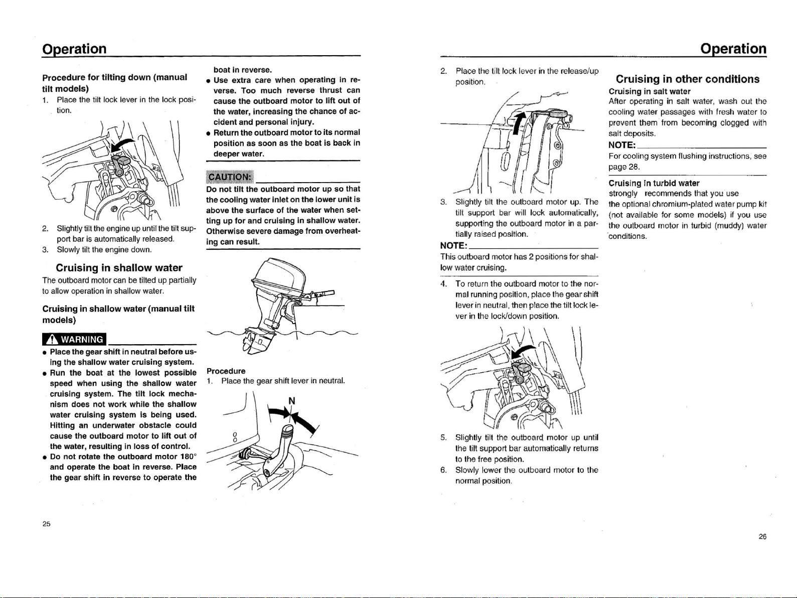
1. Pl
ace
the tilt lock lever
in
the lock posi-
tíon.
2.
Slightlyti
lt
the
engineupuntílthe tilt sup-
port bar is automatically released
3.
Slowly tilt the
engíne
down.
Cruising
in
shallow
water
The outboard motor can
be
tilted up partially
to allow operation
in
shallow water.
Cruising
in
shallow
water
(manual
tilt
models)
,
1
‘
,
'I'I!
1:
lm~[
帽
• Placethegearshiftin neutral before
us-
ingthe shallow water cruising system.
• Run the boat at the lowest possible
speed when using the shallow water
cruising system. The
tilt
lock
mecha-
nism does
not
work
while the shallow
water cruising system
is
being used.
Hitting an underwater obstacle
could
cause the outboard
motor
to
11ft
out
of
the water,resulting
in
loss
of
contro
l.
•
00
not
rotate the outboard
motor
180
。
and operate the boat
in
reverse. Place
the gear
shift
in
reverse
to
operate the
25
boat
in
reverse.
• Use extra care when operating
in
re-
verse. Too much reverse thrust can
cause the outboard
motor
to
lift
out
of
the water, increasing the chance
of
ac-
cident and personal injury.
• Returntheoutboard
motor
to
its
normal
position as soon
as
the boat
is
back
in
deeperwater.
翻黯翻
露
00
not
tilt
the outboard
motor
up
so that
thecoolingwater inleton the lower
unit
is
above the surface
of
the water when set-
ting
up
for
and cruising
in
shallow water.
。
therwise
severe damagefrom overheat-
ing can resul
t.
Procedure
1. Place the gear shift leverin neutral
2.
Place the ti
lt
lock lever
in
the release/up
position.
3.
Slightly tilt the outboard motor up. The
tilt support bar will lock automatically,
suppo
同
i
ng
the outboard motor
in
a par-
tially
ra
ised position.
NOTE:
Thisoutboard motor has 2 positions for shal-
low
wa
ter cruising.
4.
To return the outboard motor to the nor-
mal running position, place the gearshift
leverin neutral,
th
en place the tiltlock le-
ver in Ihe
lo
ckldown
posi
甘
on
.
5.
Slighlly lilt Ihe oulboard motor up until
Ihe till support bar automalically returns
10
Ihe free position.
6.
Sl
ow
ly lower Ihe outboa
rd
motor to the
normal position.
Operation
Cruising
in
other
condltlons
Cruising
in
salt
water
After operating in salt water, wash out the
cooling water passages with fresh water
10
prevent them from becoming clogged with
saltdeposits.
NOTE:
Forcooling system flushing instructions, see
page 28.
Cruising in
turbid
water
strongly recommends Ihat you use
the optional chromium-plaled waterpump kit
(not availa
ble
for some models)
if
yo
u
use
Ihe outboa
rd
molor in turbid
(m
uddy) water
co
nditions.
26

EF20:14.7kW@5000-5500r/min
EF30: 22kW@5000-5500r/min
EF20 :1000 / EF30: 1118
EF20:427 / EF30: 430
EF20:(S)1080 (L)1207 / EF30: (S)1155(L)1282
EF2 0:(S)381(L)508 / EF30: (S)431(L)558
EF20:(S)58kg (L) 60kg / EF30:(S)84kg(L)89kg
1050
EF20:323.0cm³ EF30:498cm³
or atomizer
Maintenance
lowing procedures.
剧目黯""警句盹掌重哩
Q
宝宝晒
撞
到国画姐随
袭
瓷将
强~
'!i.扁.......如硝烟盹
•
To
prevent problems
which
can be
caused
by
oil
enteringthe
cylinder
from
the
sump
, keep the outboard
motor
in
the attltude
shown
when
transpo
此
ing
and
storing
It.
If
storing
or
transp
。此
ing
the
outboard
motor
on
its
side
(not
up-
rlght),
put
It
on a
cushion
afterdraining
the
englne
oi
l.
•
00
not
place
the
outboard
motor
on
its
slde before
the
cooling water
has
dralned
from
It
comptetely, otherwlse
water
may
enter the
cylinder
through
theexhaust
port
andcauseengine
trou-
ble
.
• Store
the
outboard
motor
in
a
d町,
well
ventilated place,
not
in
direct
sunligh
t.
Procedure
Flushlng
in
a
test
tank
翻
翻
眼镇
建
00
not
run
the
englne
without
supplying
it
wlth
cooling
water. Either the engine
water
pump
will
be damaged
or
the
en-
glne
will
be damaged
from
overheating.
Before
starting the engine,
be
sure
to
supply
water
to
the
cooling
water
passag-
es
.
1. Wash the outboard motor body using
fresh water. For further information, see
page 30.
2. Disconnect the fuel line Irom the motor
or shut offthe luel cock,
il
equipped.
3.
Remove the engine top cowling and si-
lencer cover. Remove the propeller
4.
In
stall the outboard motor on the test
tank. Fill the tank with fresh water
10
29
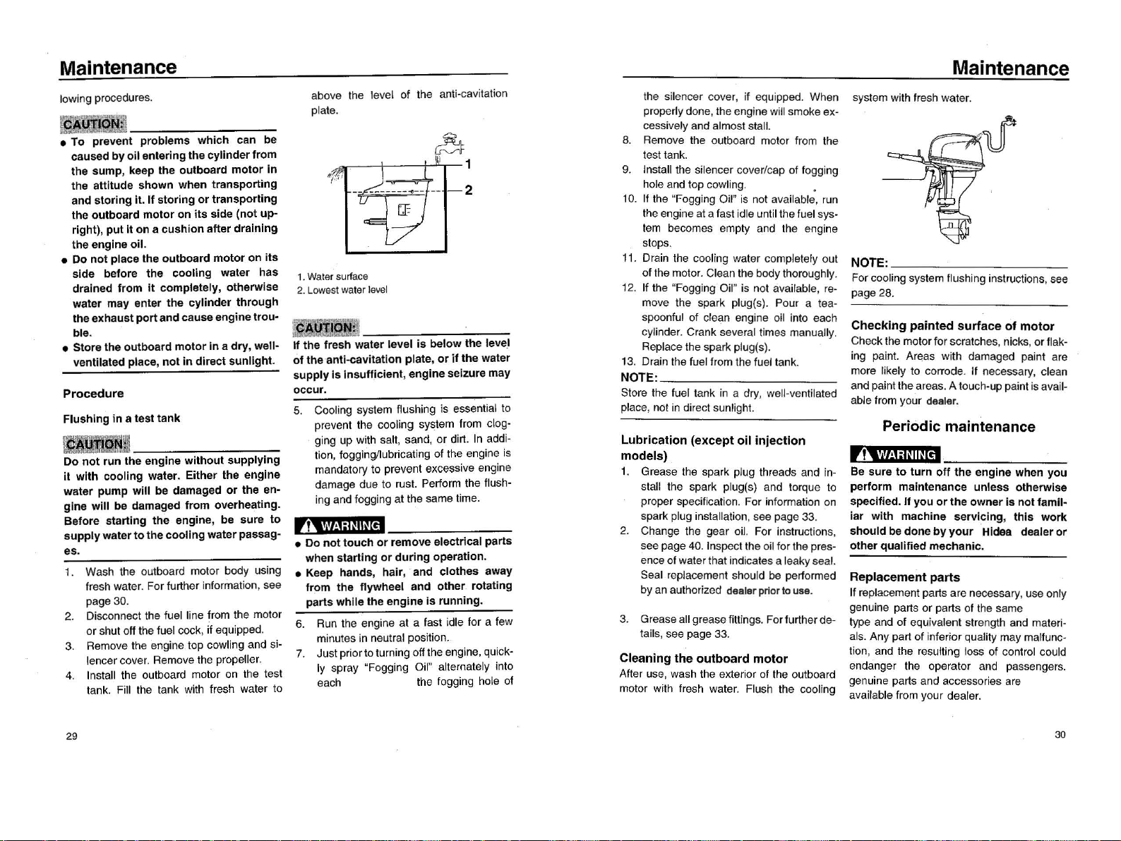
Maintenance
above the level of the anti-cavitation
plate. system with Iresh water
Ihe silencer cover,
il
equipped. When
prope
叫y
done,theengine will smoke ex-
cessively and almost stall.
8.
Remove the o
ut
board motor Irom the
aρ
test tank
9.
Install the silencer cover/cap
01
logging
hole and top cow
li
ng.
•
10.
1I
the "Fogging Oil" is not
ava
il
ab
怡,
run
the engine at a fast idle until the fuel sys-
tem
becomes empty and the engine
stops.
11.
Drain the cooling water completely out
ofthe moto
r.
Clean the body thoroughly
1
2.
1I the "Fogging Oil" is not àvailable,
re
-
move the spark plug(s). Pour a tea-
spoon
fu
l
01
clean eng
in
e
oil
into each
cylinde
r.
Crank seve
ra
l times manually
Replace the spark plug(s).
1
3.
Drain the luel lrom the luel tank
NOTE:
Store the luel tank
in
a dry, well-venlilated
place, not
in
direct sunl
igh
t.
1.
Water
surface
2.
Lowest
wa
t
er
level
翻
翻
翻
意
11
the
Iresh
water
level
is
below
the
level
01
the
anti
心
avitatlon
plate,
or
if
the
water
supply
Is
insufficient
,
engine
seizure may
occur
.
5. Cooling system Ilushing is essential to
prevent the cooling system Irom clog-
ging up with salt, sand, or dirt.
In
addi-
tion, fogging
/l
ubricating of the engine is
mandalory
10
prevent excesslve englne
damage due 10 rus
t.
Perform the flush-
ing and fogging at the sa
me
time.
Lubrication
(except
oil
injectlon
models)
1.
Grease the spark plug threads and in-
stall the spark plug(s) and torque to
proper specilication. For information
on
spark plug installation, see page 33
2.
Change the gear oi
l.
For instnuctions,
see page 40. Inspect the oil
lo
rthe pres-
ence
01
water that indicates a leakyseal.
Seal repiacement should be performed
byan authorized dealerprlor
to
use
.
r
,,
~l
h1
iWI~
[êJ
•
00
not
touch
or
remove electrical
pa
同
S
when
starting
or
during
operation.
• Keep hands,
hair
, and
clothes
away
from
the
flywheel and
other
. rotating
parts
whlle
the
engine
is
running.
6.
Run
the engine at a last idle
lor
a few
minutes in neutral position.
7. Justpriortoturning offthe engine, quick-
Iy
spray "Fogging Oil"
allern
啤
tely
into
each the logging hole 01
3.
Grease allgrease littings. Forfurtherde-
lails, see page 33
Cleaning
the
outboard
motor
After use, wash the exterior
01
the outboard
motor with Iresh water. Flu
sh
the cooling
NOTE:
Forcooling system flushing instructions,see
page 28.
Checking
painted
surface
of
motor
Checklhe motorfor scratches,nicks,
or
flak-
i
ng
pain
t.
Areas with damaged paint are
more li
ke
ly
10
corrode. If necessary, cl
ean
and paintthe areas. A touch-up paint is avail-
able from your dealer.
Periodic
maintenance
,帽
Be sure
to
turn
off
the
engine when
you
per
form
maintenance
unless
otherwlse
specified.
If
you
or
the
owner
is
not
famil-
iar
with
machine
servicing
,
this
work
should
be
done
by
your
Hidea dealer
or
other qualified mechanic.
Replacement
parts
If replacement parts
ar
e necessary,use only
genume
pa
川
s
or
parts
01
t
he
same
type and
01
equivalent strength and
mater
卜
als. Any part
01
inferiorquality may malfunc-
tion, and the resulting loss
01
contr
ol
could
endanger
th
e operator and passengers.
genuine parts and accessories are
available fr
om
your dealer.
30
Maintenance Maintenance
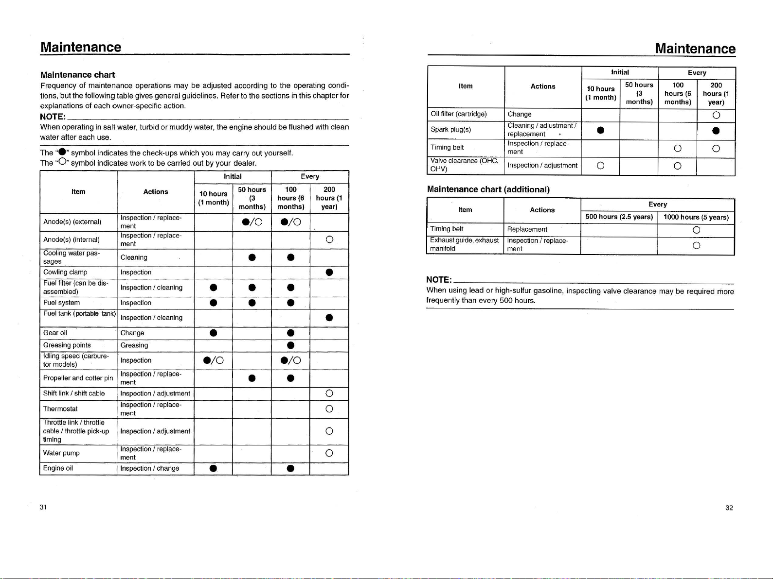
Maintenance
chart
Frequency
of
maintenance
operations
may
be
adjusted
according
to
the
operatiilg
condi-
tions
,
but
the
following
table
gives
general
guidelines.
Refer
to
the
sections
in
this
chapter
for
explanations
of
each
owner-specific
action.
NOTE:
When
operating
in
salt
water
,
turbid
or
muddy
water
,
the
engine
should
be
flushed
with
clean
water
after
each
use.
The
"."
symbol
indicates
the
check-ups
which
you
may
carry
out
yourself
The
"0"
symbol
indicates
work
to
be
carried
out
问
your
deale
r.
Initial
Every
Item
Actions
10
hours
50
hours
100 200
(1
month)
(3
hours
(6 hours
(1
months)
months)
year)
Oil filter (cartridge) Change
。
Spark
plug(S)
Clear
刊
ng
/ adjustment/ • •
replacement
Timing belt Inspection / replace-
。
。
门、
ent
Valve
clearance (OHC, Inspection / adjustment
。
。
OHV)
Initial Every
Item
Actions
10
hours
50
hours
100 200
(1
month)
(3
hours
(6
hours
(1
months) months)
year)
Anode(s) (external) Inspection I replace-
./0
./0
阿
lent
Anode(s) (internal) InspectionI replace-
。
町、
ent
Cooling water pas- Cleaning • •
sages
Cowling clamp Inspection •
Fuel filter (can be dis- Inspection/ cleaning • • •
assembled)
Fuel system Inspection • • •
Fuel tank
(阴阳
ble
恒
nk)
InspectionI cleaning •
Gearoil Change • •
Greasing points Greasing •
Idling speed (carbure- Inspection
./0 ./0
tormodels)
Propellerand cotter pin Inspection I replace- • •
阿
lent
ShiftlinkI shift cable Inspection / adjustment
。
Thermostat Inspection / replace-
。
πlent
Throttle link/ throttle
cableI throttle pick-up Inspection / adjustment
。
timing
Waterpump Inspection I replace-
。
ment
Engine oil Inspection I change • •
Maintenance
chart
(additional)
Item
Actions
e-
vs-
EJv-
m-o-0
。-
nu-
us-4·-
v--
仨』
-4"-
-s-
e-
v'-
FO-
。
hH-
RdF
T
币
Ir
阿
mln
Exhau
晦
t
guide, exhaust Ilnspection I
repla
巳
e-
man
叫
lÎ
训
i
川
10
口
Id
I
men
川
t
NOTE:
When
using
lead
or
high-sulfur
gasoline
,
inspecting
valve
clearance
may
be
required
more
frequently
than
every
500
hours.
31
32

F20EI F25EI F30EI
Maintenance
Greasing
grease A (water resistant grease)
grease D (corrosion resistant grease;
lor
propellershaft)
Cleaning
and
adjusting
spark
plug
,
1
‘
'1'1
啊
I~II~
【帽
When
removing
or
installing
a
spark
plug
,
be careful
not
to
damage
the
insulator. A
33
damaged
insulator
could
allow
external
sparks
,
which
could
lead
to
explosion
or
fire.
The spark plug is an important engine com-
ponent and is easy to inspec
t.
The condition
01
the spark plug can indicate something
about the condition
01
the engine. For exam-
ple,
il
the center electrode porcelain is very
white,this could indicate
an
intake airleak
or
carburetion problem in that cylinde
r.
Do not
attempt to diagnose any problems yoursell
Instead, take the outboard motor to a
dealer. You should periodically re
move and inspect the spark plug because
heat and deposits will cause the spark plug
to slowly break down and erode.
1I
electrode
erosion becomes excessive,
or
ifcarbon and
other deposits are excessive, you should re-
place the spark plug with another
01
the cor-
rect type.
I Standard spark plug:
DPR6EB-9
Before litting the spark plug, measure the
electrode gap with a wire thickness gauge;
adjust the gap
to
specilication if necessary.
2 1
j.
Spark
plug
gap
2.
Spark
plug
1.
0.
mark
(NGK)
Spark plug gap:
08-0.9
mm (0.031
-0
.035 in)
When litting the plug, always clean the gas-
ket surface and use a new gaske
t.
Wipe off
any dirt from the threads and screw in the
Maintenance
spark plug to the correct torque.
Spark plug torque:
18.0 Nm (13.3 ft-Ib) (1.84 kgf-m)
NOTE:
1I
a torque-wrench
is
not available when
you
are filting a spark plug, a good estimate
01
the correct torque is 1/4to 1/2 a turn pastlin-
ger-tigh
t.
Havethe spark plug adjusted tothe
correct torque as soon as possible with a
torque-wrench
Checking
fuel
system
,?‘
.'I'I~l:I~IIN
帽
Gaso
Ji
ne
and
its
vapors
are
highly
flam-
mable
and
explosive. Keep away
from
sparks
, cigarettes,
flames
,
or
other
sources
of
ignition.
,?‘四土,
1:1~
1I~['帽
Leaking fuel can
result
in
fire
or
explo-
sion.
• Check
for
fuel leakage regularly.
•
If
any
fuel leakage
is
found
,
the
fuel
system
must
be
repaired
by
a qualified
mechanic.
Improper
repairs can make
the
outboard
unsafe
to
operate.
Check the fuel lines for leaks, crack,
or
mal-
lunction.
1I
a problem is lound, your
dealer
or
otherqualilied mechanic should
r
白,
pair it immediately.
34
This manual suits for next models
1
Table of contents
Other Hidea Outboard Motor manuals


