High Voltage Audio VMC-76 User manual
VMC-76
VINTAGE MODERN COMPRESSOR
USER GUIDE
HIGHgVOLTAGE
A U D I O
WWW.HIGHVOLTAGEAUDIO.NET

!
FCAUTION: HIGHgVOLTAGE !
RISK OF ELECTRIC SHOCK
!! WARNING !!
SET AC VOLTAGE SELECTION INSIDE BEFORE USE
HEALTH AND SAFETY
- Always read these complete instructions before operating the equipment.
- Always use a properly grounded IEC cable with this equipment and never defeat the
grounding pin as this provides not only a safety ground but is required for low noise
operation.
- Avoid using this equipment around stray magnetic fields. The enclosure is designed to
shield the circuits from magnetic fields and radio interference and so during racking of
the equipment it’s important to ensure typical grounding procedures are followed.
- Avoid the use of the equipment in high temperature environments as this can degrade
the performance and reduce the lifetime of the internal components.
- There are some internally accessible adjustments in this equipment. If there is a
requirement to perform internal adjustments, please ensure one is comfortable with
opening the equipment and performing said adjustments. Please seek qualified
assistance if unsure.
- If adjustments are to be made to this equipment, please disconnect the equipment from
mains power prior to opening the equipment and performing the adjustment. While we
understand that some adjustments are to be made with the equipment live, any damage
to the equipment as a result of dropped metal objects or liquid damage will not be covered
by the warranty.
HIGH VOLTAGE AUDIO reserves the right to change the specifications or modify the designs of
its equipment. Company contact information is on the last page of this manual.
VOLTAGE SELECTION AND FUSE
This equipment is capable of operating over a range of mains voltages to cater for various
regions. Please ensure the correct mains voltage setting and correct fuse are used prior to
connecting the equipment to mains. To avoid the risk of fire, replace the mains fuse only with
the correct value.
For mains voltages from 100-120 VAC, use a T500mAL (M205 SLO-BLO only) and configure the
internal mains voltage selector to display 115V. For mains voltages from 200-240 VAC, use a
T250mAL (M205 SLO-BLO only) and configure the internal mains voltage selector to display
230V.

| 3
THANK YOU FOR CHOOSING
HIGHgVOLTAGE
A U D I O
Thank you for choosing products from HIGH VOLTAGE AUDIO. We expect you will be satisfied
with the quality, performance and value of our products, which are made possible through careful
design and construction choices.
ABOUT HIGH VOLTAGE AUDIO
HIGH VOLTAGE AUDIO is a manufacturer of boutique audio electronics based in Australia. We
go to every effort to accurately create the tone, feel and functionality of great outboard gear. Our
work is the culmination of years of experience in sound production and electronics. Our products
are built here in Australia, so our customers can have the confidence that they will purchase a
product that not only sounds great, but is dependable, reliable and easy to use.

!
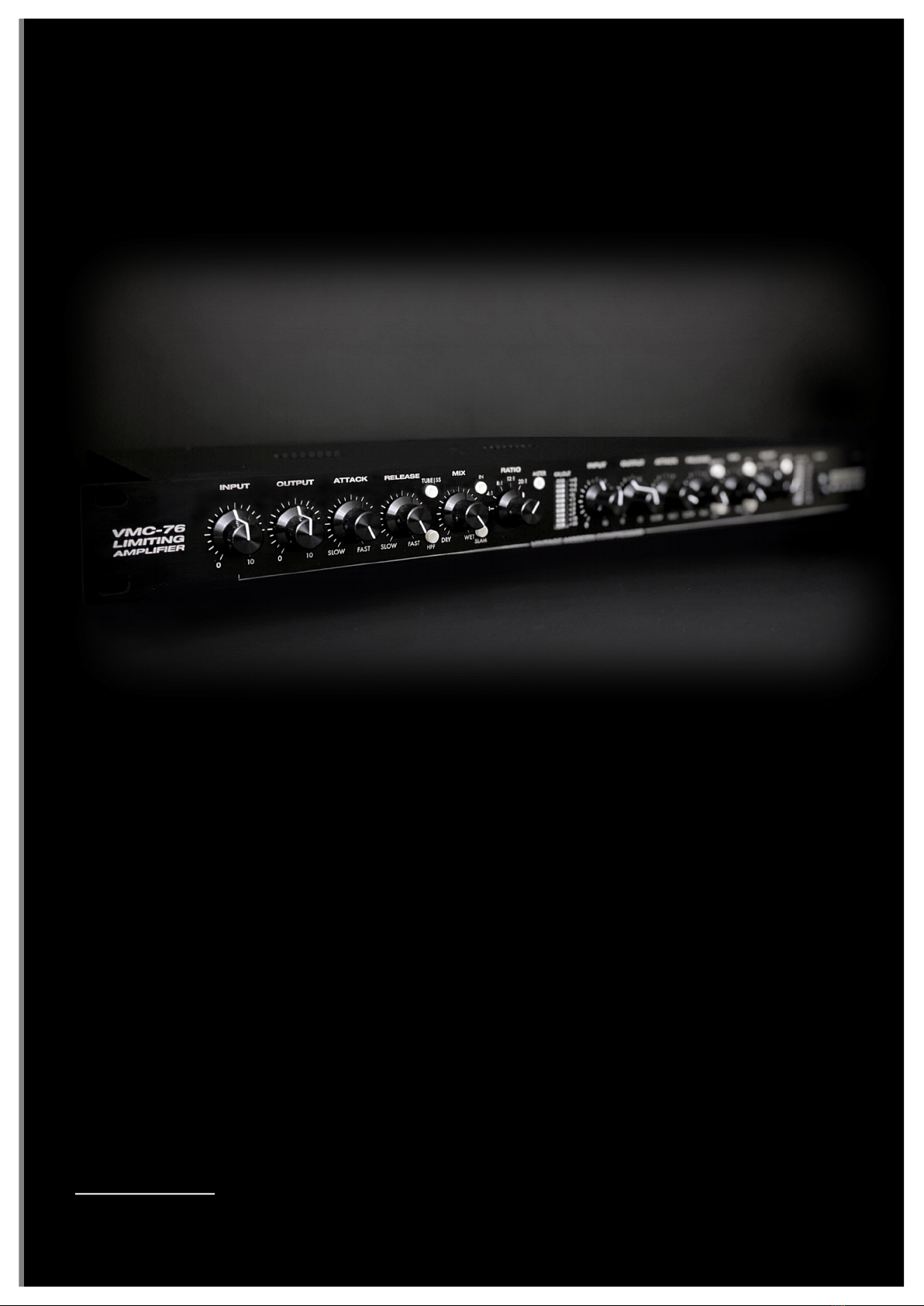
OVERVIEW
The VMC-76 is our modern take on a vintage classic - the venerable FET compressor! Instead of
reinventing the wheel, our approach was to ambitiously reimagine this iconic design. In a sea of
clones, our aim was to bring something truly unique to the table. The only thing better than one
FET compressor is two! From a form factor perspective, we have taken what is traditionally a
single channel, 2RU beast and halved the size to 1RU whilst doubling the channel count. If that
wasn't enough, there are two switchable output stages, each with a different voicing: a modern,
transparent solid state output stage and a true (not starved plate!) high voltage, colored tube
output stage.
As a dual mono/stereo unit, we have succeeded where traditional FET compressors have failed.
The FET compressors of old are notoriously difficult to use in stereo operation due to the
dependency on matched FETs across both units/channels. The unmatched FETs across separate
units and wide parts tolerances makes traditional stereo operation very problematic. To remedy
this, our units feature quad matched FETs which are painstakingly matched by hand. The use of
high tolerance components across both channels ensures accurate metering and stereo
operation where controls are set identically on both channels.
Whilst excelling on the typical sources - drums, vocals and bass, the VMC-76 also lends itself to
a typically uncommon application for FET compressors: mix bus compression. Key features
which make the VMC-76 capable of very transparent mix bus compression include: a subtle 2:1
ratio, a switchable fixed side chain high pass filter (which prevents heavy low-end content
causing over compression), a mix control, which allows you to dial in the ideal wet/dry mix ratio,
as well as enabling the quick and easy use of hardware based parallel compression. Where
transparency is not the objective, we have included the beloved "all-buttons-in" (SLAM) mode
which is a timeless favorite for squashing drums and bringing out larger than life room ambience.

| 5
front PANEL CONTROLS
The front panel features INPUT, OUTPUT, ATTACK (SLOW-FAST), RELEASE (SLOW-FAST), MIX
(DRY-WET) potentiometers and a RATIO stepped control. Push button controls consist of
TUBE|SS, HPF (@ 100Hz), SLAM, METER (GR|VU modes) and IN to engage the channel through
true bypass.
A single POWER rocker switch, when toggled, will power the unit ready for use with a red LED
indicator directly above the switch.
INPUT
The VMC-76 input control sets the level of compression, similar to the "Threshold" control of
other compressors. The higher the input level, the more the signal will cross the selected
ratio’s threshold, which in turn increases the amount of compression.
OUTPUT
The output control sets the make-up gain level of the compressor once compression has been
applied. The output control can be used to compensate for changes in gain as a result of
driving the input control to induce compression. Whilst the input control acts as a compression
‘threshold’, it also increases the overall level of the output signal. The output control can be
used to deal with this.
RATIO
The VMC-76 is equipped with 5 ratios, which range from a transparent 2:1 (soft knee) to a 20:1
(limiting). As a starting point, the 2:1 ratio is ideal for transparent, mix or stereo bus
applications. The 4:1 ratio is a good starting point ratio for general compression duties.
ATTACK and RELEASE
The “ATTACK” and “RELEASE” controls dictate how quickly the compression circuit
commences and ceases gain reduction. These two controls are key in dialing the unit’s
compression behavior on the source material. The attack is adjustable from 20 to 800
microseconds. The release control is adjustable from 50 milliseconds to 1.1. As a point of
difference to most compressors, the attack and release times get faster as the controls are
turned clockwise. This is the reverse to most typical compressors.
OUTPUT
ATTACK
RELEASE
VMC-76
LIMITING
AMPLIFIER
VINTAGE MODERN COMPRESSOR
HIGH
g
VOLTAGE
A U D I O
INPUT
RATIO
12: 1
2:1
4:1
8:1
20:1
MIX
IN
OUTPUT
ATTACK
RELEASE
INPUT
POWER
METER
TUBE|SS
HPF
SLAM
RATIO
MIX
IN
METER
TUBE|SS
HPF
SLAM
0
10
0
10
SLOW
FAST
SLOW
FAST
DRY
WET
0
10
0
10
SLOW
FAST
SLOW
FAST
DRY
WET
GR|OUT
+3
+2
+1
0
-1
-3
-5
-7
-10
-20
12: 1
2:1
4:1
8:1
20:1
+3
+2
+1
0
-1
-3
-5
-7
-10
-20
GR|OUT

!
MIX
One of the most distinctive features of the VMC-76 is its ability to mix the compressed or “wet”
signal with the dry signal using the “MIX” control. By using this control, you can create unique
effects that are typically unachievable within a standalone compressor. For instance, you can
compress a drum bus with a large amount of gain reduction, and then use the MIX control to
mix the compressed signal with the dry signal. This allows you to create a more ‘in your face’
drum sound without leaving the drums sounding lifeless and over-compressed. The MIX
control is very useful on a variety of sources including vocals, drums, guitars, sub-mixes, and
entire mixes.
TUBE|SS
This button toggles the unit between the two selectable output stages. When the button is IN,
the transformer balanced TUBE output stage is selected. When the button is OUT, the SOLID-
STATE output stage is selected. Each of the output stages lends itself to a different sonic flavor.
The TUBE output stage is more colored, whereas the SOLID-STATE, electronically balanced
output stage provides a clean and flat frequency response with very little distortion. Generally
speaking, the SOLID-STATE output stage is better suited to applications where sonic
transparency is key. The TUBE output stage on the other hand has a more obviously colored
sonic footprint.
IN
This toggle switch engages the unit’s relay switched bypass circuit. When the button is IN, the
unit is in compression mode. With the button OUT, bypass is active. The VMC-76 employs a
"true bypass", where no audio traverses the compressor signal path where the bypass is
engaged. The unit also passes audio when the unit is not powered on.
METER
This button toggles the unit between VU and GR (Gain Reduction) metering modes. When the
button is IN the meter will display the amount of gain reduction occurring. With the button
OUT, the meter will show the VU output level on the meter.
HPF
Pushing the "HPF" button IN toggles a fixed 100Hz high pass filter into the compressors side
chain circuit. This feature prevents the compressor 'over compressing' as a response to
excessive low-end frequencies. This makes the compression behavior smoother and more
transparent, which makes this mode very useful in mix bus applications where a more
transparent compression behavior is desired.
SLAM
With the selection of the 20:1 ratio and then engaging of the “SLAM” push button, the VMC-76
goes into the classic "all-buttons-in" compression mode, which is an iconic feature of FET style
compressors. This setting can be pleasing on any source that calls for heightened
saturation/excitement. It is typically used on drum room mics or as an "in your face" vocal
effect.

| 7
STEREO OPERATION
The VMC-76 is equipped with quad matched FETs. The “FET” controls the compression
behavior and metering responses. Matched FET’s across both channels ensures accurate
metering and compression behavior when using the VMC-76 across a stereo source, where the
controls are set identically on both channels. The precision matched FET's eliminate imaging
drift and ensure that both channels track accurately on stereo sub mixes and full mixes. With
the use of precision matched FETs, there is no need for a 'Stereo Link'. There are no 'master'
controls and all control knob settings must be duplicated manually on both channels. Also
ensure that the push buttons engaged are the same on both channels.
If required, the accuracy of stereo operation can be verified using a sine wave input signal.
Leaving all controls at the desired positions, feed a sine wave signal to both channels from
your DAW (the level and frequency are not important). Observe the gain reduction meters on
both channels. If one channel is displaying a differing level of gain reduction, adjust the input
control on one channel until both meters show the same level of gain reduction.
Now observe the output level in your DAW and if there is a difference in output between both
channels, simply adjust the output control of one channel until both channels show the
identical output level in your DAW. This process is a 'sanity check' and is not required in
ordinary operation, however it is helpful as a quick quality check to ensure that your stereo mix
is being processed evenly across both channels.
REAR PANEL CONNECTIONS
The rear panel features XLR INPUT and OUTPUT connectors for the LEFT and RIGHT channels.
These connections have been wired PIN 2 HOT to conform with AES standards.
NOTE: To run in unbalanced mode, ensure your unbalanced cable ties pin 3 to pin 1 at the cable.
The AC INPUT connection is a typical 3 pin IEC power cable. You must use the correct fuse value
and ensure the internal voltage selector meets the requirements for your region.
PLEASE REFER TO THE VOLTAGE SELECTION AND FUSE SECTION ON PAGE 2 PRIOR TO
POWERING YOUR UNIT.
LEFT CHANNEL
OUTPUT
INPUT
AC INPUT
F
CAUTION: HIGH
g
VOLTAGE
!
RISK OF ELECTRIC SHOCK. DO NOT OPEN.
REFER TO USER MANUAL BEFORE SERVICING.
!! WARNING !!
SET AC VOLTAGE SELECTION INSIDE BEFORE USE.
RIGHT CHANNEL
OUTPUT
INPUT
!
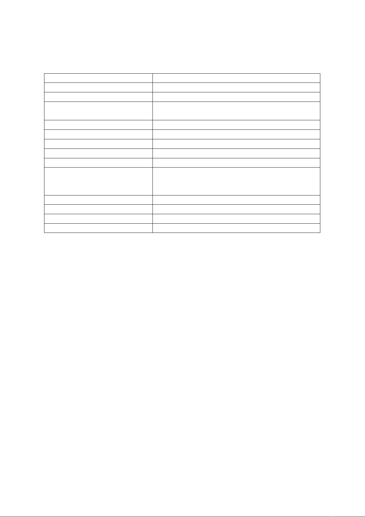
SPECIFICATIONS
Compressor Type
Field-Effect Transistor (FET)
Channels
Two (2) channel, dual mono
Rack space
19” 1RU
Controls
INPUT, OUTPUT, ATTACK, RELEASE, RATIO (stepped),
MIX
Ratios (5 step rotary switch)
2:1, 4:1, 8:1, 12:1, 20:1
Attack (potentiometer)
SLOW - FAST
Release (potentiometer)
SLOW - FAST
Pushbuttons
TUBE/SS, HPF (@ 100Hz), IN, SLAM, METER
Inputs & Outputs
Balanced 3 pin XLR with relay bypass
Output Stages
(Switchable) between solid state electronically
balanced output and transformer balanced, tube gain
stage using 2 x ECC88 tubes
THD
0.5% or better
Noise Floor
-80dB or better
Replacement fuses (M205)
USA (100-120VAC) 500mA Slo-Blo
EU, AU (200-240VAC) 250mA Slo-Blo
*Specifications subject to change without notice.

| 9
WARRANTY & REPAIR
High Voltage Audio warrant our products with a standard warranty period of one (1) year from
the date of purchase for parts and labour, subject to inspection. Products will be free of
manufacturing defects. This warranty does not include damage incurred through shipment,
rough user operation of the product or modifications or attempted repair by unauthorized
personnel. This warranty is offered solely to the original purchaser of the product, directly from
High Voltage Audio and is not transferrable. This warranty does not include shipping charges to
and from High Voltage Audio.
In the event you require repair or warranty assistance with your unit, you should first initiate
contact through our contact page on our official website, outlining any issues in detail. The
information provided will be assessed to determine the best outcome for repair.
Any unit failures within a period of seven (7) days are liable for a direct replacement upon receipt
and assessment of the defective unit. The customer is responsible for immediately notifying High
Voltage Audio of defective units within this period.
Any unit failures outside of a period of seven (7) days will be covered under a full twelve (12)
month warranty period from the date of purchase, including parts and labour. The customer will
be responsible for return freight to High Voltage Audio. High Voltage Audio will cover freight
back to the customer for repaired or replaced units. No other shipping/taxes are included.
Exceptions to the above cases will be assessed on an individual basis with the customer to
determine a mutual agreement.
Warranty service communication must be conducted directly through High Voltage Audio.
High Voltage Audio reserves the right to alter the design of their products and specifications
without notice.
CONTACT
web: http://www.highvoltageaudio.net
facebook: http://www.facebook.com/hvaudio
instagram: http://www.instagram.com/hvaau
email: [email protected]

!
HIGHgVOLTAGE
A U D I O

| 11
!
COPYRIGHT © 2021 HIGH VOLTAGE AUDIO
!
Table of contents


