Metrohm 830 User manual
830 IC Interface
Instuctions for Use
8.830.1003
CH-9101 Herisau/Switzerland
E-Mail [email protected]
Internet www.metrohm.com


CH-9101 Herisau/Switzerland
E-Mail [email protected]
Internet www.metrohm.com
830 IC Interface
5.830.0020 Program
Instructions for Use
8.830.1003 07.2003 / pkl

Teachware
Metrohm AG
Oberdorfstrasse 68
CH-9101 Herisau
1st Edition 2003
These instructions are protected by copyright. All rights reserved.
Although all the information given in these instructions has been checked with great care, errors
cannot be entirely excluded. Should you notice any mistakes please inform the author at the
address given above.

Table of contents
830 IC Interface / 8.830.1003 Instructions for Use I
Table of contents
1Introduction.................................................... 1
1.1 Instrument description ............................................................. 1
1.2 Parts and controls..................................................................... 2
1.3 Information on the Instructions for Use................................... 4
1.3.1 Organization ..................................................................................4
1.3.2 Notation and pictograms ..............................................................5
1.4 Safety notes .............................................................................. 6
2Installation ..................................................... 7
2.1 Setting up the instrument ......................................................... 7
2.1.1 Packaging......................................................................................7
2.1.2 Check.............................................................................................7
2.1.3 Location .........................................................................................7
2.1.4 Arrangement of the instruments....................................................7
2.2 Mains connection...................................................................... 8
2.2.1 Mains voltage and fuses ...............................................................8
2.2.2 Mains cable ...................................................................................8
2.2.3 Switching the instrument on/off.....................................................8
2.3 Connection to the PC................................................................ 9
2.3.1 Connecting cable ..........................................................................9
2.3.2 Software installation ......................................................................9
2.4 Connection of external instruments....................................... 10
2.4.1 General information.....................................................................10
2.4.2 819 IC Detector, 820 IC Separation Center, 818 IC Pump .........12
2.4.3 833 IC Liquid Handling Pump Unit .............................................13
2.4.4 833 IC Liquid Handling Suppressor-Unit ....................................14
2.4.5 833 IC Liquid Handling Sample Prep Unit ..................................15
2.4.6 833 IC Liquid Handling Dialysis Unit...........................................16
2.4.7 833 IC Liquid Handling Ultra Filtration Unit.................................17
2.4.8 Triathlon Autosampler .................................................................18
2.4.9 766 IC Sample Processor ...........................................................19
2.4.10 791 IC VA Detector ......................................................................20
2.4.11 761 Compact IC ..........................................................................21
2.4.12 812 IC Valve Unit and 817 Bioscan.............................................22
2.4.13 816 IC Eluent Selector.................................................................23
2.4.14 828 IC Dual Suppressor ..............................................................24
2.4.15 837 IC Combi Degasser..............................................................25
3Operation...................................................... 26
3.1 Switch instrument on/off ........................................................ 26
3.2 Settings in the "830 IC Interface" window.............................. 27
3.2.1 Event output lines ........................................................................30
4Appendix ....................................................... 34
4.1 Technical data......................................................................... 34
4.2 Scope of delivery .................................................................... 38
4.3 Optional accessories .............................................................. 39
4.4 Validation / GLP ...................................................................... 40
4.5 Warranty and Conformity ....................................................... 41

Table of contents
830 IC Interface / 8.830.1003 Instructions for Use
II
4.5.1 Warranty ...................................................................................... 41
4.5.2 Declaration of Conformity ........................................................... 42
4.5.3 Quality Management Principles .................................................. 43
4.6 Index ........................................................................................ 44
List of illustrations
Fig. 1: Connection possibilities at 830 IC Interface .............................................. 1
Fig. 2: Front of 830 IC Interface............................................................................ 2
Fig. 3: Rear of 830 IC Interface............................................................................. 3
Fig. 4: Connection of 830 IC Interface to PC........................................................ 9
Fig. 5: Connection of 819, 820 and 818 (MIC 1) ................................................ 12
Fig. 6: Connection of 820, 819, 818 and 833(Pump Unit) (MIC 2) ..................... 13
Fig. 7: Connection of 2×819, 820, 2×818 and 833 (Suppressor Unit) (MIC 3).. 14
Fig. 8: Connection of 833 (Sample Prep Unit) to MIC 6 for Neutralization......... 15
Fig. 9: Connection of 819, 820, 818, 833 (Suppressor Unit)
and 833 (Dialysis Unit) ............................................................................ 16
Fig. 10: Connection of 819, 820, 818, 833 (Suppressor Unit)
and 833 (Ultra Filtration Unit)................................................................... 17
Fig. 11: Connection of 819, 820, 818 and Triathlon ............................................. 18
Fig. 12: Connection of 819, 820, 818 and 766 ..................................................... 19
Fig. 13: Connection of 819, 820, 818 and 791 ..................................................... 20
Fig. 14: Connection of 819, 820, 818 and 761 ..................................................... 21
Fig. 15: Connection of 817, 812 and 818 (MIC 8) ................................................ 22
Fig. 16: Connection to 819, 820, 818 and 816 ..................................................... 23
Fig. 17: Connection to 819, 820, 2x818 and 828 (MIC 10)................................... 24
Fig. 18: Connection to 819, 820, 818 and 837 ..................................................... 25
1.1 Instrument description
1 Introduction
1.1 Instrument description
The 830 IC Interface provides the connection between the PC and ex-
ternal IC or HPLC peripheral instruments. Up to 16 instruments includ-
ing 4 detectors can be connected to the 830 IC Interface and controlled
by means of the «IC Net»PC software. The 830 IC Interface can also
record and convert the analog signals from a maximum of 4 channels
(two at once) which are processed at very high resolution.
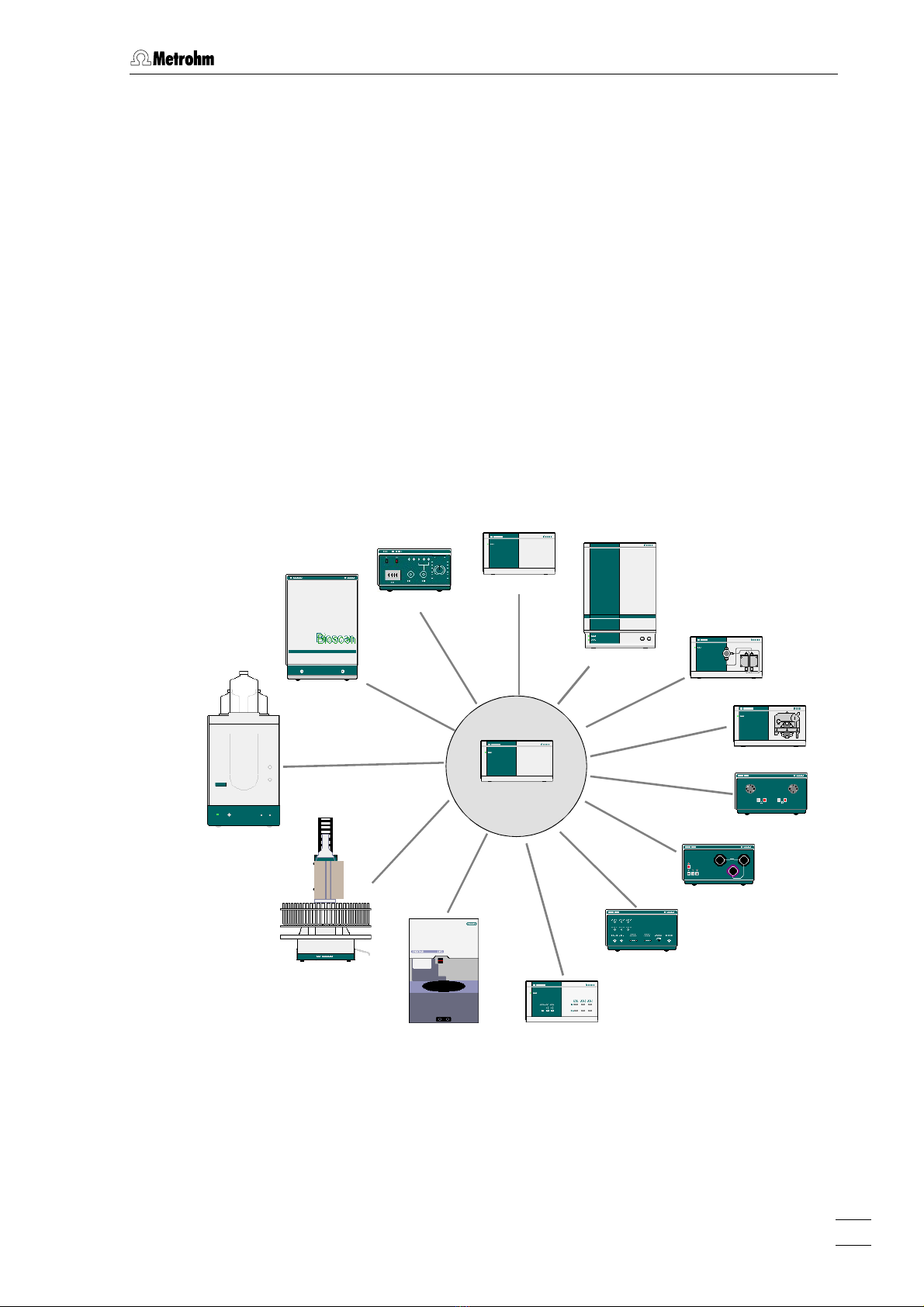
Fig. 1 shows an overview of all the Metrohm instruments which can be
connected to the 830 IC Interface and are described in these ‘Instruc-
tions for Use’. It is also possible to connect Bischoff instruments;
please refer to the «IC Net»on-line program help as well as the relevant
Bischoff instruction manuals.
830 IC Interface
819 IC Detector
820 IC Separation Center
818 IC Pump
833 IC Liquid Handling Unit
812 IC Valve Unit
816 IC Eluent Selector
817 Bioscan
761 Compact IC
791 IC VA Detector
766/788 IC Sample Processor
828 IC Dual Suppressor
837 IC Inline Degasser
Triathlon Autosampler
Fig. 1: Connection possibilities at 830 IC Interface
830 IC Interface / 8.830.1003 Instructions for Use 1

1 Introduction
1.2 Parts and controls
In this section you will find the numbers and designations of the parts
and controls of the 830 IC Interface. The numbering applies through-
out the instructions for use, i.e. bold numbers in the text (e.g.
5
) refer
to the parts and controls illustrated here.
1
Fig. 2: Front of 830 IC Interface
1Mains pilot lamp
Lights up when instrument is switched
on
830 IC Interface / 8.830.1003 Instructions for Use
2
1.2 Parts and controls
2 3
4 5
7 8 9 10 11 12 13 14
6
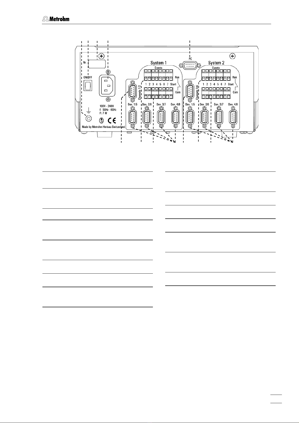
Fig. 3: Rear of 830 IC Interface
2
Earthing socket
3
Mains switch
For switching the instrument on/off.
4Serial number
5Mains connection plug
Mains connection see section 2.2
6PC connection
RS232 interface
System 1
7Analog signal connection
8Remote input/output lines connec-
tion (RUN)
9Remote input/output lines connec-
tion (COM)
10 RS232 interfaces
System 2
11 Analog signal connection
12 Remote input/output lines connec-
tion (RUN)
13 Remote input/output lines connec-
tion (COM)
14 RS232 interfaces
830 IC Interface / 8.830.1003 Instructions for Use 3

1 Introduction
1.3 Information on the Instructions for Use
Please read through these Instructions for Use carefully before you put
the 830 IC Interface into operation. The Instructions for Use contain
information and warnings to which the user must pay attention in order
to assure safe operation of the instrument.
1.3.1 Organization
These 8.830.1003 Instructions for Use for the 830 IC Interface pro-
vide a comprehensive overview of the installation, startup procedure,
operation and technical specifications of this instrument. The Instruc-
tions for Use are organized as follows:
Section 1 Introduction
General description of instrument, parts and con-
trols and safety notes
Section 2 Installation
Mains connection, connection to PC,
connection of external instruments
Section 3 Operation
Operation via «IC Net»
Section 4 Appendix
Technical data, standard equipment, options, war-
ranty, declarations of conformity, index
To find the required information on the instruments you will find it an
advantage to use either the Table of contents or the Index at the
back.
830 IC Interface / 8.830.1003 Instructions for Use
4
1.3 Information on the Instructions for Use
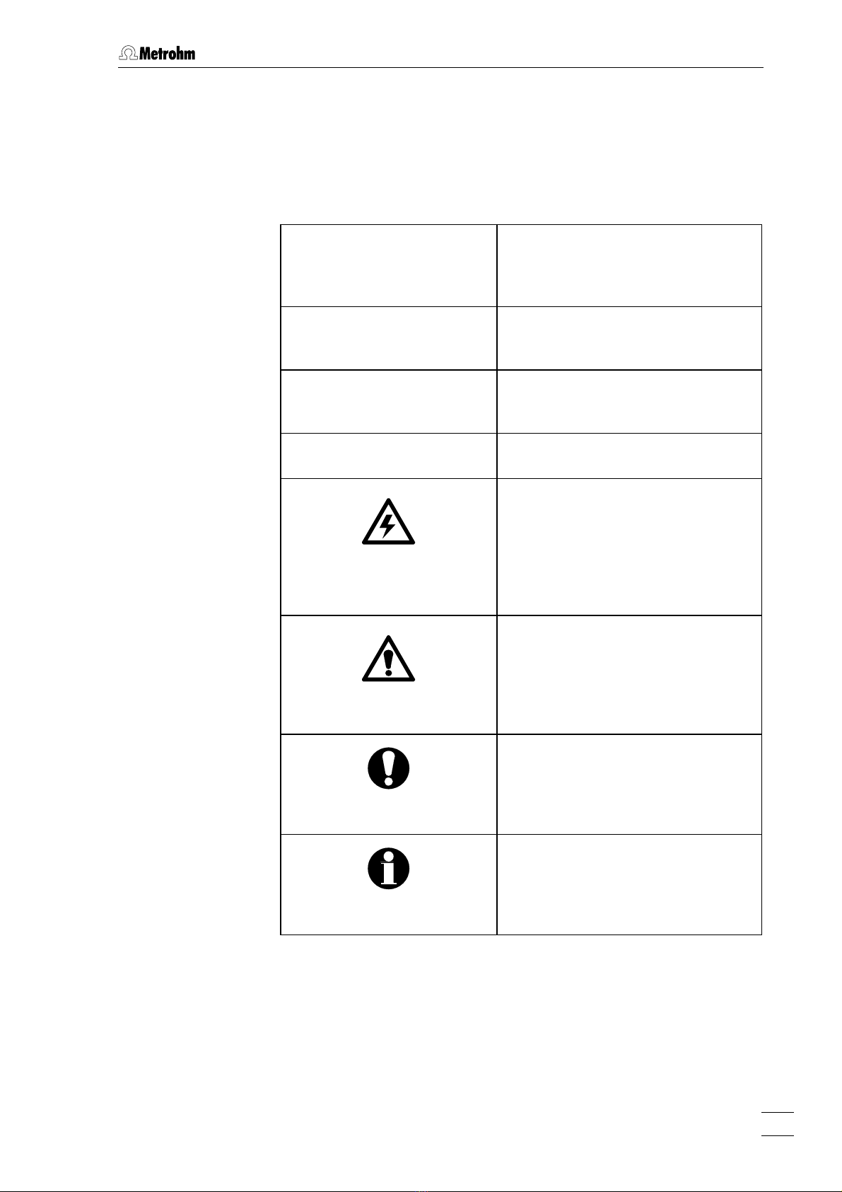
1.3.2 Notation and pictograms
The following notations and pictograms (symbols) are used in these In-
structions for Use:
Range Menu item, parameter or entry
value
in «IC Net» program
SYSTEM STATE Program window
in «IC Net» program
<OK> Button
in «IC Net» program
4 Part or control of 830
Danger/Warning
This symbol indicates a possible
risk of death or injury to the user
and possible damage to the
instrument or its components by
electricity.
Danger/Warning
This symbol indicates a possible
risk of death or injury to the user
and possible damage to the
instrument or its components.
Attention
This symbol indicates important
information that you should read
before continuing.
Information
This symbol indicates additional
information and tips which may be
of particular use to you.
830 IC Interface / 8.830.1003 Instructions for Use 5

1 Introduction
1.4 Safety notes
While electrical safety in the handling of the 830 IC Interface is assured
in the context of the specifications IEC 1010-1 (protection class 1, de-
gree of protection IP40), the following points should be noted:
• Mains connection
The mains connection must be effected in accordance with the
instructions in section 2.2.
• Opening the instrument
Inside the instrument there are no parts which must be set or adjusted
by the user.
If the 830 IC Interface is connected to the power supply, the instru-
ment must not be opened nor must parts be removed from it, other-
wise there is a danger of coming into contact with components which
are live. Hence, always disconnect the instrument from all voltage
sources before you open it and ensure that the mains cable is
disconnected from mains connection
5
!
• Protection against static charges
Electronic components are sensitive to static charging and can be
destroyed by discharges. Before you touch any of the components
inside the 830 IC Interface, you should earth yourself and any tools
you are using by touching an earthed object (e.g. housing of the
instrument or a radiator) to eliminate any static charges which exist.
830 IC Interface / 8.830.1003 Instructions for Use
6
2.1 Setting up the instrument
2 Installation
2.1 Setting up the instrument
2.1.1 Packaging
The 830 IC Interface is supplied together with the separately packed
accessories in special packagings containing shock-absorbing foam
linings designed to provide excellent protection. The instrument itself is
packed in an evacuated polyethylene bag to prevent the ingress of
dust. Please store all these special packagings as only they assure
transport of the instrument free from damage.
2.1.2 Check
After receipt, immediately check whether the shipment is complete and
has arrived without damage (compare with delivery note and list of
accessories in section 4.2). In the case of transport damage, see
instructions in section 4.5.1 "Warranty".
2.1.3 Location
Position the instrument in the laboratory at a location convenient for op-
eration, free from vibrations and protected against a corrosive atmos-
phere and contamination by chemicals.
2.1.4 Arrangement of the instruments
The modular IC instruments can be piled up in any order. The best
place for the 830 IC Interface is on top of a modular IC system.
The 830 IC Interface should always be placed above components
carrying liquids so that any leaks which may occur in the tubing or
connections cannot cause damage by leakage of liquids (e.g. acid).
830 IC Interface / 8.830.1003 Instructions for Use 7

2 Installation
2.2 Mains connection
2.2.1 Mains voltage and fuses
The 830 Interface has a power supply which automatically adjusts itself
to the existing mains voltage (100…240 V) and frequency (50…60 Hz).
It is equipped with an electronic overload protection device and also
has two fuses; however, these should only be exchanged by Metrohm
service technicians.
2.2.2 Mains cable
The instrument is supplied with one of three mains cables
• 6.2122.020 with plug SEV 12 (Switzerland, …)
• 6.2122.040 with plug CEE(7), VII (Germany, …)
• 6.2133.070 with plug NEMA 5-15 (USA, …)
which are three-cored and fitted with a plug with an earthing pin. If a dif-
ferent plug has to be fitted, the yellow/green lead (IEC standard) must
be connected to the earthing socket 2(protection class 1).
Any break in the earthing inside or outside the instrument can make it
a hazard!
Plug the mains cable into mains connection plug 5at the 830 IC Inter-
face (see Fig. 3).
2.2.3 Switching the instrument on/off
The 830 IC Interface is switched on and off using mains switch 3(see
Fig. 3). When the instrument is switched on a start-up check routine is
running the mains pilot lamp 1flashes twice slowly and remains on.
830 IC Interface / 8.830.1003 Instructions for Use
8

2.3 Connection to the PC
2.3 Connection to the PC
2.3.1 Connecting cable
Always switch off 830 IC Interface and PC before you connect the two
instruments with the 6.2134.100 Cable
Connect the PC connection 6at the 830 IC Interface to one of the serial
COM ports at the PC using the 6.2134.100 Cable (9 pin/9 pin). If only a
25-pin COM interface is available on the PC then the 6.2125.110
Adapter cable or a commercially available adapter must be used.
830
6.2134.100
Fig. 4: Connection of 830 IC Interface to PC
2.3.2 Software installation
The PC program «IC Net 2.3» is required for the operation of the 830 IC
Interface; this is contained on the 6.6034.033 CD included in the acces-
sories. This program runs under Windows 2000 and Windows XP oper-
ating systems and is installed according to section 1.4.2 of the «IC Net»
Instructions for Use.
830 IC Interface / 8.830.1003 Instructions for Use 9

2 Installation
2.4 Connection of external instruments
2.4.1 General information
Before an external instrument is connected to the 830 IC Interface, the
830 IC Interface must always be switched off using mains switch
3
!
Each system of the two versions of the 830 IC Interface has four RS232
interfaces 10 or 14 for connection of a maximum of 8 external instru-
ments, an 7 or 11 interface for analog signals from a maximum of 2 de-
tectors and 8 remote output lines 8/9 or 12/13 for controlling external
instruments by making contacts or impulses (see Fig. 3). Information
about the technical data of these interfaces is given in section 4.1.
For installation and startup of external instruments proceed as follows:
1 Switch off all instruments
• Switch off 830 IC Interface and all external instruments using
the mains switch.
2 Connect instruments
• Connect the instruments to the 830 IC Interface according to
the connection diagrams shown in sections 2.4.2 to 2.4.15 by
using the cables named in the diagrams. Other instrument
combinations can be set up by using these examples as a
guide.
3 Switch on all instruments
• Switch on 830 IC Interface and all external instruments using
the mains switch.
4 Instrument settings
Operation with the 830 IC Interface requires that the following
settings must be made:
• Advanced IC instruments:
818 IC Pump
819 IC Detector
820 IC Separation Center
833 IC Liquid Handling Unit
These instruments are already pre-configured, no additional
settings must be made.
Also all other Metrohm IC instruments can be operated with the
830 IC Interface, for the settings of the instruments please refer
to the respective instructions for use.
• 732 IC Detector:
>CONFIG/RS settings
handshake: SWchar
830 IC Interface / 8.830.1003 Instructions for Use
10
2.4 Connection of external instruments
>CONFIG/RS settings
RS control: on
• 709 IC Pump:
Switch on external control of the 709 IC Pump using the
[ EXT. ] key.
• 752 IC Pump Unit, 753 IC Suppressor Module,
754 IC Dialysis Unit:
Switch on external control via remote interface using the
[ Remote ] switch.
• 817 Bioscan:
This instrument is already pre-configured, no additional set-
tings must be made.
• 761 Compact IC:
This instrument is already pre-configured, no additional set-
tings must be made.
• 750 IC Autosampler:
Always switch on the 830 IC Interface first and then the 750
Autosampler.
• 766 IC Sample Processor:
>RS232 settings
handshake: SWchar
>RS232 settings
RS control: on
• Triathlon Autosampler:
This instrument is already pre-configured, no additional set-
tings must be made.
• 812 IC Valve Unit:
This instrument is already pre-configured, no additional set-
tings must be made.
• 816 IC Eluent Selector:
Switch on external control via RS232 interface using the
[ EXT ] switch..
• 828 IC Dual Suppresso:
Switch on external control via remote interface using the
[ Remote ] switch.
• 837 IC Degasser:
This instrument is already pre-configured, no additional set-
tings must be made.
5 Create new system in «IC Net»
• Start the «IC Net»program.
• Create a new system file with the selected instruments (de-
tails see IC Net Instructions for Use).
830 IC Interface / 8.830.1003 Instructions for Use 11

2 Installation
2.4.2 819 IC Detector, 820 IC Separation Center, 818 IC Pump
Example
Analysis of anions or cations on a modular system with electronic sup-
pression.
Instruments
The setup of the instruments corresponds to the Modular IC System 1
(MIC 1 Advanced).
• 2.830.0020 830 IC Interface
• 2.819.0110 819 IC Detector
• 2.820.0210 820 IC Separation Center with 1 injector and
column heater
• 2.818.0110 818 IC Pump
819
820
818830
PC
6.2134.100
6.2134.130
6.2115.070
6.2134.090
6.2125.090
6.2134.040
Interconncection
Fig. 5: Connection of 819, 820 and 818 (MIC 1)
830 IC Interface / 8.830.1003 Instructions for Use
12

2.4 Connection of external instruments
2.4.3 833 IC Liquid Handling Pump Unit
Example
Analysis of anions or cations on a modular system with chemical sup-
pression.
Instruments
The setup of the instruments corresponds to the Modular IC System 2
(MIC 2 Advanced).
• 2.830.0020 830 IC Interface
• 2.819.0110 819 IC Detector
• 2.820.0230 820 IC Separation Center with 1 injector,
suppressor module and column heater
• 2.818.0110 818 IC Pump
• 2.833.0010 833 IC Liquid Handling Pump Unit
833
819
820
818830
PC
6.2134.100
6.2134.130
6.2115.070
6.2134.090
6.2125.090
6.2128.180
6.2134.040
Interconnection
Fig. 6: Connection of 820, 819, 818 and 833(Pump Unit) (MIC 2)
830 IC Interface / 8.830.1003 Instructions for Use 13

2 Installation
2.4.4 833 IC Liquid Handling Suppressor-Unit
Example
Simultaneous analysis of cations and anions on a modular system with
two independent detectors.
Instruments
The setup of the instruments corresponds to the Modular IC System 3
(MIC 3 Advanced).
• 2.830.0020 830 IC Interface
• 2.819.0010 819 IC Detector for System 1 (cations)
• 2.819.0110 819IC Detector für System 2 (anions)
• 2.820.0220 820 IC Separation Center with 2 injectors and
column heater
• 2.818.0110 818 IC Pump, for System 1 (cations)
• 2.818.0110 818 IC Pumpe, for System 2 (anions)
• 2.833.0020 833 IC Liquid Handling Suppressor Unit,
for System 2 (anions)
Interconnection
819-2
819-1
820
818-1830
PC 6.2134.100
6.2115.070
6.2134.090
6.2125.090
6.2143.200
833
818-2
6.2125.090
6.2115.070
6.2134.090
6.2128.180
6.2134.130
6.2134.130
6.2134.040
Fig. 7: Connection of 2
×
819, 820, 2
×
818 and 833 (Suppressor Unit)
(MIC 3)
830 IC Interface / 8.830.1003 Instructions for Use
14
Table of contents
Popular Recording Equipment manuals by other brands


Solid State Logic
Solid State Logic SSL UC1 user guide

Gotharman
Gotharman Little deFormer Quick manual

Yamaha
Yamaha MDR-2 user guide

Doepke
Doepke Dupline DFA-DI operating instructions

PS Engineering
PS Engineering PMA4000 TSO Pilot's guide and operation manual

Worthington
Worthington DIATROL Installation & operation instructions


