HIKOKI CC 14ST User manual
中 文
English
高速切割机
Cut-OffMachine
CC 14ST
使用说明书
Handling instructions
保留备用
Keep for future reference
000BookCC14STChS.indb1000BookCC14STChS.indb1 2017/12/1211:33:502017/12/1211:33:50

2
中文
作业上的一般注意事项
警告!
当使用电动工具时,为了减少造成火灾、电击和人身伤害,必须时刻遵守基本
注意事项,以及下述操作注意事项。
在操作本机之前,请通读本说明书,并予以妥善保管。
安全操作注意事项∶
1. 工作埸所应打扫干净,清理妥当,杂乱无章将导致事故。
2. 确保妥适的作业环境。电动工具不可任其风吹雨打。不得在潮湿的地方作业。
工作埸所需保持充分的亮度。请勿在有可能造成火灾或爆炸的地方使用电动
工具。
3. 谨防触电事故。应避免身体同大地或接地表面不可让访客触摸电动工具或延
伸线缆接触(例如∶管道、散热器、炉灶、冰箱等)
4. 不可让孩童靠近工作埸所。与作业无关的访客也必须保持安全距离。
5. 不使用的电动工具应存放到干燥而孩童伸手不及的高处,并加锁保管。
6. 不得使劲用力推压。电动工具需按设计条件才能有效而安全地工作,绝不可
勉强。
7. 妥选使用工具。不可用小型工具或附件去干重活。不可用于规定外的作业。
举例说,用圆锯进持伐木打枝或原木锯切作业。
8. 工作时衣服穿戴要合适。不要让松散的衣角和宝石类卷入转动部份。屋外作
业时,最好手戴橡胶手套,脚穿防滑胶鞋。同时要戴上能够罩笼长发的工作帽。
9. 绝大多数的电动工具作业时,均需戴安全眼镜。进行粉尘飞扬的切削作业时,
需戴防尘面罩。
10. 连接除尘设备
如果提供连击除尘和集尘的设备,请确认是否已经连接好并且使用正常。
11. 不要拿电线提起电动工具,也不得拉扯电线从电源插座拆除插头。电线需从
热源和油液隔开,并避免与锐利的边缘接触。
目次
作业上的一般注意事项...............................2
使用高速切割机前的注意事项................3
符号.......................................................................4
部件名称.............................................................4
规格.......................................................................5
标准附件.............................................................5
用途.......................................................................5
作业之前.............................................................5
切割顺序.............................................................6
切割轮的装卸...................................................7
操作方法.............................................................8
维护和检查.....................................................10
维修零部件一览表......................................11
000BookCC14STChS.indb2000BookCC14STChS.indb2 2017/12/1211:33:512017/12/1211:33:51

3
中文
12. 作业以安全第一为原则。工件要用夹具或台钳卡紧。这样做,比用手按压更
为可靠,也能够让双手专心操作。
13. 作业时脚步要站稳,身体姿势要保持平衡。
14. 工具应维护妥善,经常保持锋利、清洁才能充分发挥性能,落实作业安全的
要求。应按规定加注润滑脂、更换附件。线缆应定期检查,如发现损伤应即
委托专业性的服务单位加以修复。延伸电缆如有损伤应予更换。手柄要保持
干燥,并防止沾附油脂类。
15. 不使用时,维修前以及更换附件(如∶刀具、钻头、锯具等)之前,都必须
拆卸电源插头才行。
16. 开动前务必把调整用键和扳手类拆除下来。这一点与安全有关。应养成习惯,
严格遵守。
17. 谨防误开动。插头一插上电源插座,指头就不可随便接触电源开关。插接电
源之前,应先确认∶开关是否切断。
18. 屋外延伸线缆的使用,屋外作业时,必须使用专用的延伸线缆。
19. 保持高度警觉,充分掌握情况,以正常的判断力从事作业。疲惫时切不可开
动电动工具。
20. 检查损坏部件。在继续使用电动工具之前,应详细检查各部零件以及防护装
置有无损坏,以便判断具能否正常工作,能否发挥正常效能。检查转动部份
的对准、空转、各零件有无异常,安装是否妥善以及其它足以给工作带来不
良影响的情况。如防护以及其它零件损伤了。除非本说明已有记载否则应即
委托服务中心进行妥善修理或更换。开关一发现缺陷,应即委托服务中心加
以更换。如开关不能正常地接通或切断,绝不可使用该电动工具。
21. 警告
使用非本说明书中的推荐的附件可能有发生人身损害的危险。
22. 本工具必须委托有资格的维修人员进行维修。本电动工具满足相关的安全要
求。维修必须由专业人员使用纯正配件来进行。否则有可能会给用户造人身
损害。
使用高速切割机前的注意事项
1. 使用前请检查切割轮,不要使用有缺口的或有缺陷的切割轮。使用前请始终
进行试运转以确认高速切割机无异常。
2. 请使用正常切割轮的正常工作面。
3. 请注意防护火花。
4. 请正确更换切割轮。
5. 请始终注意切割轮夹紧部件未出现破损。有缺陷的部件将导致切割轮破损。
6. 请确保工件不带钉子等异物。
7. 只使用厂家推荐的具有等于或大于本机标牌上标注的速度的切割轮。
8. 应按照厂家指示保管和操作研磨轮。
000BookCC14STChS.indb3000BookCC14STChS.indb3 2017/12/1211:33:512017/12/1211:33:51

4
中文
9. 切实按照厂家指示安装切割轮。
10. 切勿在没有防护的状态下使用本机。
11. 不要锯刀具。
12. 不要在爆炸性氛围和火花会引起火灾、爆炸等的氛围中使用本机。
符号
警告!
如下所示的符号用于本机。使用前请务必理解其含意。
为降低伤害风险,用户必须阅读使用说明书
部件名称
图 1
轮罩
下侧防护
装置 (A)
下侧防护
装置 (B)
把手
手提把手
火花档槽
六角条形扳手
接合器
螺丝柄
锁链 夹具 (A)底座 夹具 (B)
开关
把手
图 2
000BookCC14STChS.indb4000BookCC14STChS.indb4 2017/12/1211:33:512017/12/1211:33:51
5
中文
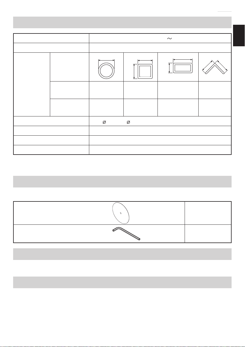
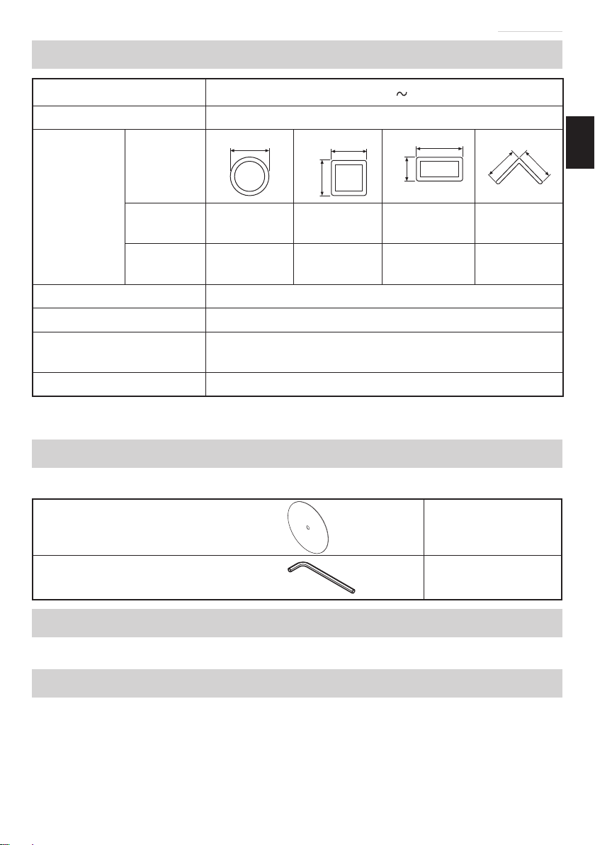
规格
电压 220 V
输入功率 2200 W
最大切割尺
寸*
高度×宽度
被切割材料
的形状
AA
A
B
A
A × B
A
A
切割角度 0°130 mm 120 mm 95 mm×
200 mm 137 mm
切割角度 45°115 mm 104 mm 115 mm×
104 mm 100 mm
切割轮 355 × 25.4 × 4 mm (增强树脂切割轮)
空载转速 3800 /min
最大圆周速度 4800 m /min
重量 (不含线缆) 17.0 kg
* 最大切割尺寸是指磨石在没有因切割材料而造成明显磨损的状态下所可能切
割的尺寸。
标准附件
除了主机 (1 台) 外,产品包中还包括表中所列的附件。
切割轮 1
六角条形扳手 1
用途
切割各种金属材料,诸如管子、圆棍和型钢。
作业之前
1. 电源
确认所使用的电源与工具铭牌上标示的规格是否相符。
2. 电源开关
确认电源开关是否切断。若电源开关接通,则插头插入电源插座时电动工具
将出其不意地立刻转动,从而招致严重事故。
000BookCC14STChS.indb5000BookCC14STChS.indb5 2017/12/1211:33:522017/12/1211:33:52

6
中文
3. 延伸线缆
若作业场所移到离开电源的地点,应使用容量足够、装合适的延伸线缆,并
且要尽可能地短些。
4. 必须将切割机安装在平坦的地方,并使其保持稳固状态。为防止在操作时发
生触电事故,出厂前已对切割机进行了严格检查。
5. 运输时,因本工具的可动部分被用锁链张力固定住,因此,请轻按开关柄,
从锁链钩上卸下锁链。
6. 必须确认所有切割轮都处于良好状态,必须无刮伤、无裂缝。
7. 虽然夹紧螺母在出厂前已被拧紧,但为了安全请重新将其拧紧。
8. 保护罩 (轮罩) 能预防事故发生,例如能防止破裂的切割轮飞散。虽然固定
螺丝在出厂前已被拧紧,但为了安全请重新将其拧紧。
9. 更换切割轮时,必须确认所更换的切割轮的设计圆周速度是否在 4800 m /min
以上。
10. 必须确认用于拧紧或拆卸切割轮的条形扳手确实没留在切割机上。
11. 检查工件是否被适当支撑住。
必须用夹具将材料固定住。否则,在作业期间材料松弛或切割轮破损的话会
引起严重事故。
12. 使用前应切实正确安装和紧固研磨轮,并在安全的场所在空载状态下运转本
机 30 秒钟,如果发现剧烈震动或其它问题请立即停下。在这种情况下,请
检查本机,确定原因。
13. 请旋转切割轮,检查其表面上的缺陷。缺陷严重时,会造成切割轮移位。
14. 在多尘环境中作业时请确保通风口清洁。如需清洁尘埃,请先将本机与主电
源断开。
切割顺序
注意!
在切割轮旋转时装卸工件是十分危险的。
1. 操作开关
拉开关后会接通电源 ;放开开关后会切断电源。
拉开关时按下开关锁后,即使放开开关后也能继续操作。
再次拉开关后放开开关可解除开关锁。
2. 切割
(1) 旋转切割轮,轻轻按下把手,使切割轮靠近要切割的材料。
(2) 切割轮碰到要切割的材料后,再进一步轻轻按下把手,开始切割。
(3) 完成切割 (或切进所设计的槽深) 后,提起把手,使其返回原来位置。
(4) 每次切割结束后,都必须关掉开关。等高速切割机完全停止转动后,才能进
行下一项切割作业。
000BookCC14STChS.indb6000BookCC14STChS.indb6 2017/12/1211:33:522017/12/1211:33:52

7
中文
注意!
用力按把手并不能加快切割速度。相反,过分用力按把手会给马达增加不必
要的负担并降低切割能力。完成作业后,必须关掉开关并将电源插头从插座
上拔出。
切割轮的装卸
1. 拆卸切割轮 (图 3 和 4)
(1) 提起下侧防护装置 (A) 和下侧防
护装置 (B)。按下止动销,使其与
箔垫圈相接触。转动砂轮,将止
动销穿过箔垫圈上的孔,然后用
附带的六角扳手拆下 M10 螺栓。
(2) 卸下螺栓、垫圈 (A) 和轮垫圈并
拆下切割轮。(图 4)
注意!
不要将 O 形环或套筒从砂轮主轴
上拆下。
2. 安装切割轮
将轮垫圈及螺栓上的灰尘完全擦
净,然后按与上述拆卸步骤相反
的顺序安装切割轮。将下侧防护
装置 (A) 和下侧防护装置 (B) 放
回原来位置。
注意!
请确认用于安装和拆卸切割轮的止动销已返回到缩回位置。
止动器 止动销 箔垫圈孔
10 mm 螺栓
六角条形扳手
轮垫圈 切割轮
图 3
套筒 砂轮主轴
止动销
轮垫圈
O形环
切割轮
垫圈 (A)
10 mm 螺栓
轮垫圈
图 4
000BookCC14STChS.indb7000BookCC14STChS.indb7 2017/12/1211:33:522017/12/1211:33:52

8
中文
操作方法
1. 固定切割材料的步骤 (图 5 和 6)
如图 5 所示,将工件材料置于夹具 (A)
和夹具 (B) 之间,拉起接合器并按螺丝
柄以使夹具 (A) 轻轻接触到工件材料。
然后将接合器转下,转动螺丝柄将工
件材料牢牢地固定在正确位置。当切
割作业完成时,请转动螺丝柄两三次
以松开夹具 (A),并卸下工件材料 (如
图 6 所示)。
注意!
为了避免受伤,在切割轮转动期间切
勿卸下或安装工件材料。
2. 角切割 (图 7)
(1) 本工具可以 0 度或 45 度的斜角进行
切割。
(2) 松开夹具 (B) 上的两个 M10 六角形套
筒扳手头螺栓,然后将夹具卡爪上的
工作表面设于 0 度、30 度或 45 度中
的任意一个角度。完成设定之后,拧
紧两个 M 10 六角形套筒扳手头螺栓。
3. 移动夹具的固定卡爪 (图 8)
本工具出厂时,夹具开口被设定为
最大 165 mm,需要使夹具开口大于
165 mm,请旋松两个螺栓后,将夹具
移到锁线所示的位置。最大张口可被
设为两档,即 200 mm 和 235 mm。当
切割材料太宽时,需要重新设定夹具
的卡爪后才能有效地发挥夹具的作用。
夹具 (B) 夹具 (A)
长工件材料
工件材料
底座 螺丝柄
图 5
夹具 (B) 夹具 (A)
接合器
螺丝柄
工件材料
底座
图 6
夹具 (B)
10 mm 螺栓
图 7
六角条形扳手
165 mm
200 mm
235 mm
夹具 (B)
10 mm 螺栓
夹具 (A)
图 8
000BookCC14STChS.indb8000BookCC14STChS.indb8 2017/12/1211:33:522017/12/1211:33:52

9
中文
4. 切割长工件材料 (图 9)
开始作业前务必将长工件材料的两端放在与
底座高度相同的块上,以将其固定住。
5. 如何使用方块 (图 10)
切割轮的外径减小时,可在夹具 (A) 和 (B)
之间插入比被切割工件的尺寸稍小一些的方
块,以便经济地使用切割轮。
6. 调节切割深度 (图 11)
切割轮的外径减小时,可改变止动螺栓的高
度,以调节切割深度。调节方法为松开锁定
螺母,并旋转止动螺栓。调节完后,请重新
拧紧锁定螺母以固定止动螺栓。
对有的材料可以去除碎片。
注意!
更换砂轮后务必重新调节止动螺栓的高度。
如果止动螺栓太低,砂轮可能会切割到底座。
7. 调节火花板 (图 12)
用菲利浦螺丝刀松开固定火花板的螺丝以调
节角度。
根据环境和所需作业改变角度,以调节火花
飞溅的方向。
8. 运送本工具 (图 13)
移动本工具时,请将锁链钩勾在锁链上,握
着手提把手移动。
螺丝
火花档槽
图 12 图 13
手提把手 锁链钩
锁链
长工件材料
块块
底座
图 9
夹具 (A)
被切割工
件的尺寸
夹具 (B)
块
方块的尺寸
图 10
止动螺栓
锁定螺母
图 11
000BookCC14STChS.indb9000BookCC14STChS.indb9 2017/12/1211:33:522017/12/1211:33:52
10
中文
维护和检查
注意!
在检查或维护之前,请务必关掉电源开关并从电源插座上拔下插头。
1. 更换切割轮
长时间使用后当切割轮变钝时,会给马达增加不必要的负担。因此,必须修整
切割轮或换上新的切割轮以保证切割效果。
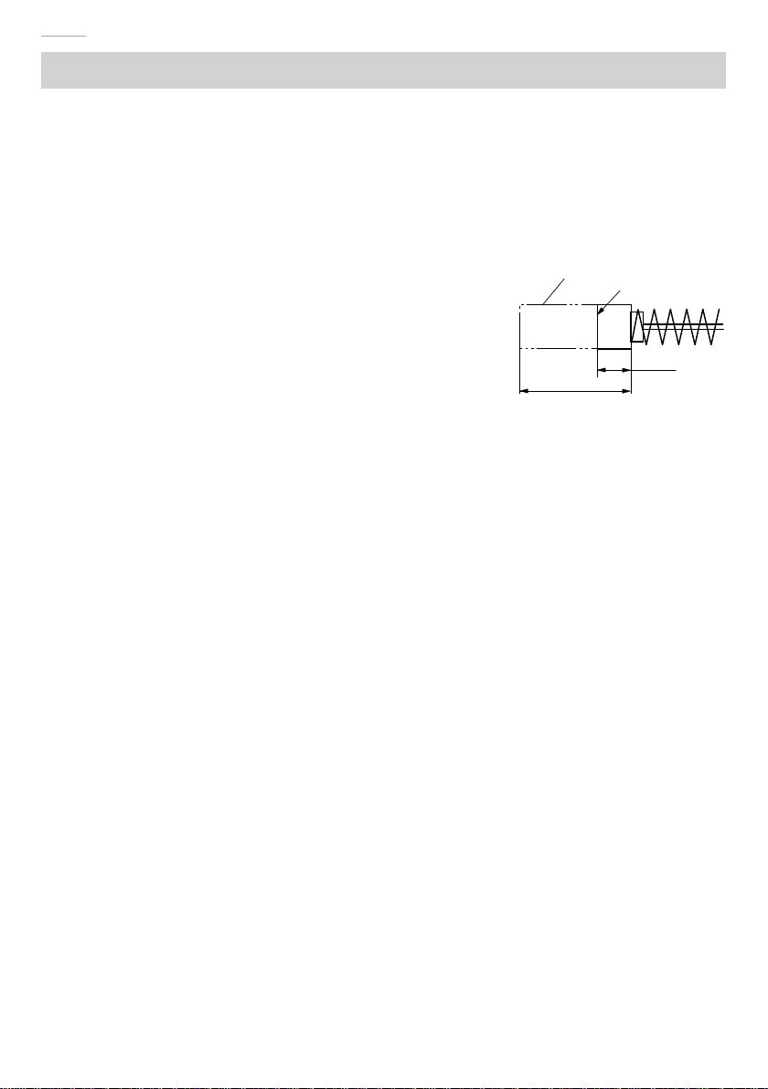
2. 检查炭刷 (图 14)
电动机上的炭刷是一种消耗品,其磨耗程度一旦超
出了“磨耗极限”,电动机将发生障碍。因此,磨耗
了的炭刷应即更换新件。此外,炭刷必需常保干净
状态,这样才能在刷握里自由滑动。
3. 检查安装螺钉
要经常检查安装螺钉是否紧固妥善。若发现螺钉松
了,应立即重新扭紧,否则会导致严重的事故。
4. 更换电源线
必须更换电源线时,应由HiKOKI公司授权的维修中心来更换,以避免安全危
险。
5. 润滑
请每月在下述润滑部添加一次机油,以延长切割机的使用寿命。
○ 轴承旋转部
○ 夹具旋转部
○ 夹具 (A) 的滑道
6. 清洗
必须经常用布将机身上的切屑和灰尘擦掉。请小心不要用机油或水弄湿马达
部分。
7. 维修零部件一览表
注意!
HiKOKI牌电动工具的维修、改造和检查须由经HiKOKI公司授权的维修中心
进行。
当要求维修或其他保养服务时,若将此零部件一览表与电动工具一起呈交给
经HiKOKI公司授权的维修中心,将有助于维修或保养工作。
在操作和维修电动工具时,必须遵守贵国制定的安全的有关规则和标准。
18 mm
6 mm
炭刷 磨损极限
图 14
000BookCC14STChS.indb10000BookCC14STChS.indb10 2017/12/1211:33:532017/12/1211:33:53
11
中文
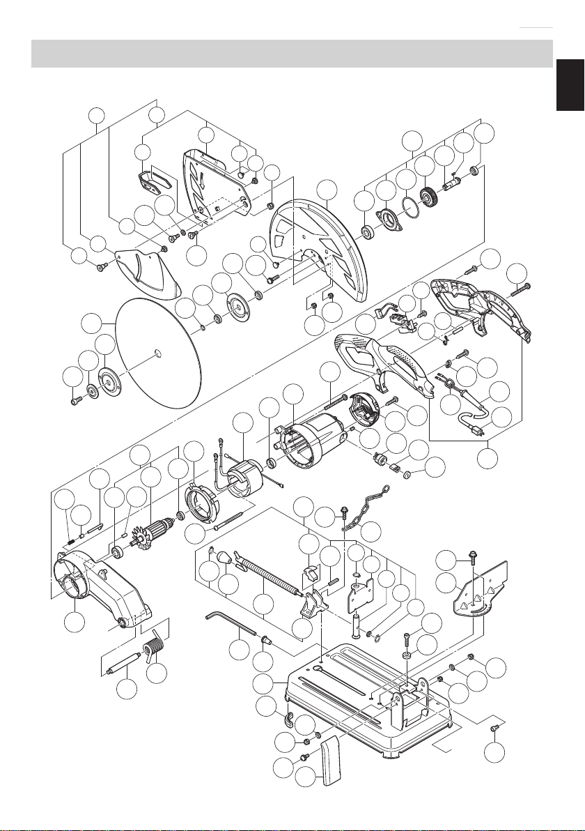
维修零部件一览表
45
53
A
A
82
2
1
3
4
556
78
910 11
12
13
14
15
16
1718 16
18 19
5
20
21
22 23 2425 26 27 28
2930
31
32
33
34
35 36
37 38
39
40
41 42
43
44
46
47 48
49
50
51 49
52 54
55
49
56
60 57 58
59
61
62
63
64
65 66
67
68
69 70
71
72
73
74
75 76
77 78
79
80 81
83
8485
65
86
87
88
89
3073 74
90
000BookCC14STChS.indb11000BookCC14STChS.indb11 2017/12/1211:33:532017/12/1211:33:53

12
中文
项目
号零件名称 数量
1 下侧防护装置 1
2 下侧防护装置 1
3 下侧防护衬垫 1
4 下侧防护 1
5 橡胶衬垫 4
6 M5螺母 1
7 M5×10法兰螺丝 1
8子罩 1
9 橡胶衬垫 1
10 M6×15法兰螺丝 1
11 板垫圈 1
12 M5×10法兰螺丝 1
13 砂轮 1
14 M10内六角螺栓 1
15 法兰垫圈 1
16 轮垫圈 2
17 O形环 1
18 轴套筒 2
19 M5×25螺丝 4
20 轮罩 1
21 齿轮组 1
22 滚珠轴承 1
23 轴承固定器 1
24 O形环 1
25 齿轮 1
26 主轴 1
27 键 1
28 滚珠轴承 1
29 M5螺母 1
30 M6螺母 2
31 弹簧 1
32 销套筒 1
33 止动销 1
34 电枢组件 1
35 滚珠轴承 1
36 橡胶销 1
项目
号零件名称 数量
37 电枢 1
38 滚珠轴承 1
39 风扇导架 1
40 定子 1
41 橡胶套筒 1
42 外罩 1
43 M5×55螺丝 4
44 噪声抑制器 1
45 开关 1
46 D4×10自攻螺丝 1
47 钩 1
48 针辊 1
49 D4×16自攻螺丝 10
50 M5×45螺丝 3
51 线夹 1
52 铁氧体环 1
53 线保护壳 1
54 电线 1
55 把手组 1
56 尾盖 1
57 刷握 2
58 炭刷 2
59 刷盖 2
60 M5×8内六角螺丝 2
61 齿轮箱 1
62 回转支架轴 1
63 扭力弹簧 1
64 D5×80自攻螺丝 2
65 D8扣环 2
66 夹具把手 1
67 夹具螺丝 1
68 螺丝固定器 1
69 六角条形扳手 1
70 扳手固定器 1
71 底座 1
72 底座橡胶 4
000BookCC14STChS.indb12000BookCC14STChS.indb12 2017/12/1211:33:542017/12/1211:33:54

13
中文
项目
号零件名称 数量
73 D10垫圈 2
74 M10螺母 2
75 M6×12螺丝 1
76 火花流道 1
77 夹具组 1
78 M8×30内六角螺栓 2
79 锁链 1
80 夹具螺母 1
81 滚销 1
82 D16扣环 1
83 可动夹具 1
84 夹具轴 1
85 D8垫圈 1
86 M10×20内六角螺栓 2
87 固定夹具 1
88 M10×45内六角螺栓 1
89 M10止动螺母 1
90 M6×12内六角螺栓 1
000BookCC14STChS.indb13000BookCC14STChS.indb13 2017/12/1211:33:552017/12/1211:33:55

English
14
GENERAL OPERATIONAL PRECAUTIONS
WARNING!
When using electric tools, basic safety precautions should always be followed to reduce
the risk of fire, electric shock and personal injury, including the following.
Read all these instructions before operating this product and save these instructions.
For safe operations:
1. Keep work area clean. Cluttered areas and benches invite injuries.
2. Consider work area environment. Do not expose power tools to rain. Do not use
power tools in damp or wet locations. Keep work area well lit.
Do not use power tools where there is risk to cause fire or explosion.
3. Guard against electric shock. Avoid body contact with earthed or grounded
surfaces. (e.g. pipes, radiators, ranges, refrigerators).
4. Keep children away. Do not let visitors touch the tool or extension cord. All visitors
should be kept away from work area.
5. Store idle tools. When not in use, tools should be stored in a dry, high or locked up
place, out of reach of children.
6. Do not force the tool. It will do the job better and safer at the rate for which it was
intended.
7. Use the right tool. Do not force small tools or attachments to do the job of a heavy
duty tool. Do not use tools for purposes not intended; for example, do not use
circular saw to cut tree limbs or logs.
8. Dress properly. Do not wear loose clothing or jewellery, they can be caught in
moving parts. Rubber gloves and non-skid footwear are recommended when
working outdoors. Wear protecting hair covering to contain long hair.
9. Use eye protection. Also use face or dust mask if the cutting operation is dusty.
10. Connect dust extraction equipment.
If devices are provided for the connection of dust extraction and collection
facilities ensure these are connected and properly used.
CONTENTS
GENERAL OPERATIONAL PRECAUTIONS................................................ 14
PRECAUTIONS ON USING CUT-OFF MACHINE .......................................15
SYMBOL.......................................................................................................16
NAME OF PARTS.........................................................................................16
SPECIFICATIONS........................................................................................ 17
STANDARD ACCESSORIES .......................................................................17
APPLICATIONS............................................................................................17
PRIOR TO OPERATION...............................................................................17
CUTTING PROCEDURES............................................................................18
MOUNTING AND DISMOUNTING THE CUT-OFF WHEEL.........................19
HOW TO OPERATE .....................................................................................20
MAINTENANCE AND INSPECTION ............................................................22
SERVICE PARTS LIST.................................................................................23
000BookCC14STChS.indb14000BookCC14STChS.indb14 2017/12/1211:33:552017/12/1211:33:55

English
15
11. Do not abuse the cord. Never carry the tool by the cord or yank it to disconnect it
from the receptacle. Keep the cord away from heat, oil and sharp edges.
12. Secure work. Use clamps or a vise to hold the work. It is safer than using your hand
and it frees both hands to operate tool.
13. Do not overreach. Keep proper footing and balance at all times.
14. Maintain tools with care. Keep cutting tools sharp and clean for better and safer
performance. Follow instructions for lubrication and changing accessories. Inspect
tool cords periodically and if damaged, have it repaired by authorized service
center. Inspect extension cords periodically and replace, if damaged. Keep handles
dry, clean, and free from oil and grease.
15. Disconnect tools. When not in use, before servicing, and when changing
accessories such as blades, bits and cutters.
16. Remove adjusting keys and wrenches. Form the habit of checking to see that keys
and adjusting wrenches are removed from the tool before turning it on.
17. Avoid unintentional starting. Do not carry a plugged-in tool with a finger on the
switch. Ensure switch is offwhen plugging in.
18. Use outdoor extension leads. When tool is used outdoors, use only extension
cords intended for outdoor use.
19. Stay alert. Watch what you are doing. Use common sense. Do not operate tool
when you are tired.
20. Check damaged parts. Before further use of the tool, a guard or other part that is
damaged should be carefully checked to determine that it will operate properly and
perform its intended function. Check for alignment of moving parts, free running
of moving parts, breakage of parts, mounting and any other conditions that may
affect its operation. A guard or other part that is damaged should be properly
repaired or replaced by an authorized service center unless otherwise indicated
in this handling instructions. Have defective switches replaced by an authorized
service center. Do not use the tool if the switch does not turn it on and off.
21. Warning
The use of any accessory or attachment, other than those recommended in this
handling instructions, may present a risk of personal injury.
22. Have your tool repaired by a qualified person.
This electric tool is in accordance with the relevant safety requirements. Repairs
should only be carried out by qualified persons using original spare parts.
Otherwise this may result in considerable danger to the user.
PRECAUTIONS ON USING CUT-OFF MACHINE
1. Inspect the cutting wheel before use, do not use chipped or otherwise defect
cutting wheels. Always make a trial run before use to confirm that the Cut-off
Machine does not involve abnormalities.
2. Use the normal cut-offwheel on its normal working surface.
3. Guard against cut-offsparks.
4. Properly replace the cut-offwheel.
5. Always pay attention that the cut-offwheel clamping parts are never impaired.
Defective parts will cause damage to the cut-offwheel.
000BookCC14STChS.indb15000BookCC14STChS.indb15 2017/12/1211:33:552017/12/1211:33:55

English
16
6. Ensure that the workpiece is free of foreign matter such as nails.
7. Use only cutting wheels recommended by the manufacturer which have a marked
speed equal to or greater than the speed marked on the nameplate of the machine.
8. Abrasive wheels shall be stored and handled with care in accordance with
manufacturer’s instructions.
9. Ensure that mounted wheel are fitted in accordance with the manufacture’s
instructions.
10. Do never use the machine without the guard in place.
11. Do not saw blade.
12. Do not use the machine in explosive atmospheres and environments where sparks
could fire, explosion etc.
SYMBOL
WARNING
The following show symbols used for the machine. Be sure that you understand their
meaning before use.
To reduce the risk of injury, user must read instruction manual.
NAME OF PARTS
Clutch Wheel cover
Lower
guard (A)
Lower
guard (B)
Handle
Carrying handle
Spark chute
Hex. bar wrench
Screw handle
Chain Vise (A) Base Vise (B)
Fig. 1 Switch
Handle
Fig. 2
000BookCC14STChS.indb16000BookCC14STChS.indb16 2017/12/1211:33:552017/12/1211:33:55
English
17
SPECIFICATIONS
Voltage 220 V
Power input 2200 W
Max. cutting
dimensions*
Height × width
Shape of
material to
be cut
AA
A
B
A
A × B
A
A
Cutting
angle 0° 130 mm 120 mm 95 mm ×
200 mm 137 mm
Cutting
angle 45° 115 mm 104 mm 115 mm ×
104 mm 100 mm
Cut-offwheel ø355 × ø25.4 × 4 mm (Reinforced resinoid cut-offwheel)
No-load speed 3800 /min
Max. working peripheral
speed 4800 m/min
Weight (without cord) 17.0 kg
* The maximum cutting dimensions are the permissible cutting dimensions when the grinding
stone is not remarkably worn by cutting material.
STANDARD ACCESSORIES
In addition to the main unit (1 unit), the package contains the accessories listed in the below.
Cut-offwheel 1
Hex. bar wrench 1
APPLICATIONS
Cutting of various metallic materials such as pipes, round bars and shaped steel.
PRIOR TO OPERATION
1. Power source
Ensure that the power source to be utilized conforms to the power requirements specified
on the product nameplate.
000BookCC14STChS.indb17000BookCC14STChS.indb17 2017/12/1211:33:562017/12/1211:33:56

English
18
2. Power switch
Ensure that the power switch is in the OFF position. If the plug is connected to a power
receptacle while the power switch is in the ON position, the power tool will start operating
immediately, which could cause a serious accident.
3. Extension cord
When the work area is removed from the power source, use an extension cord of sufficient
thickness and rated capacity. The extension cord should be kept as short as practicable.
4. Install the machine on a level flat place, and keep it in a stable condition. Prior to shipping,
the equipment is subjected to a rigid factory inspection to prevent electric shocks during
operation.
5. Since movable portions are secured by tension of a chain while in transit, remove the chain
from the chain hook by slightly depressing the switch handle.
6. Ascertain that all cut-offwheels are in perfect condition, and do not display scars and
cracks.
7. Although they have been fully clamped at the factory prior to delivery, reclamp the clamping
nuts securely for safety.
8. Possible accidents such as a cracked cut-offwheel is prevented by this protective cover
(wheel cover). Although it has been fully clamped at the factory prior to delivery, securely
reclamp the mounting screws for safety.
9. When replacing the cut-offwheel, ensure that the replacement cutting wheel has a
designed circumferential speed in excess of 4800 m/min.
10. Ensure that the bar spanner used for tightening or removing the cut-offwheel is not
attached to the machine.
11. Check that the work piece is properly supported.
Ensure that the material is securely fastened with the vise. If it is not, a serious accident
could be caused if the material comes loose or the cut-offwheel breaks during operation.
12. Ensure that the abrasive wheel is correctly fitted and tightened before use and run
the machine at no-load for 30 seconds in safe position, stop immediately if there is a
considerable vibration or if other defects are detected. If this condition occurs, check the
machine to determine the cause.
13. Rotate the cut-offwheel to inspect any facial deflection. A heavy deflection will cause the
cutoffwheel to shift.
14. Ensure that ventilation openings are kept clear when working in dusty conditions. If it
should become necessary to clear dust, first disconnect the machine from the mains
supply.
CUTTING PROCEDURES
CAUTION
It is dangerous to remove or install the workpiece while the cut-offwheel turning.
1. Operating the switch
Power will be turned on when the switch is pulled, and turned offwhen released.
Press the switch lock when the switch is being pulled to enable operations to be continued
ever after the switch is released.
Release the switch after it is pulled again to release the switch lock.
000BookCC14STChS.indb18000BookCC14STChS.indb18 2017/12/1211:33:562017/12/1211:33:56

English
19
2. Cutting
(1) Rotate the cut-offwheel, gently press down the handle, and bring the cut-offwheel close to
the cutting material.
(2) When the cut-offwheel contacts the cutting material, gently press down the handle further
and start cutting.
(3) When cutting (or designated slotting) is completed, raise the handle and restore it to its
original position.
(4) At the termination of each cutting process, turn OFF the switch to stop rotation and proceed
with the subsequent cutting job.
CAUTION
It does not necessarily cut rapidly when putting more force on the handle.
Too much force on the handle will put excessive pressure on the motor and reduce
its capacity.
Do not fail to switch OFF the switch after operation is completed and pull the plug
out.
MOUNTING AND DISMOUNTING THE CUT-OFF WHEEL
1 Dismounting the cut-offwheel (Fig. 3
and 4)
(1) Raise Lowergurd (A) and Lowergurd (B).
Press down on the stopper pin to bring it
into contact with the wheel washer.
Rotate the cut-offwheel, pass the
stopper pin through the hole on the
wheel washer, and then remove the
M10 bolt with the hexagonal spanner
supplied.
(2) Remove the bolt, washer (A), and the wheel
washer and detach the cut-offwheel. (Fig. 4)
CAUTION
Do not remove the O-ring or sleeve from
the cut-offwheel spindle.
2. Mounting the cut-offwheel
Throughly remove dust from the wheel
washers and bolt then mount the wheel by
following the dismounting procedures in
reverse order. Return Lowergurd (A) and
Lowergurd (B) to its original position.
CAUTION
Confirm that the stopper which was used for installation and removal of the cut-off
wheel has returned to the retract position.
Stopper Stopper pin Hole of wheel washer
10 mm bolt
Hex. bar wrench
Wheel washer
Cut-off
wheel
Fig. 3
Sleeve
Cut-off
wheel
spindle
Stopper pin
Wheel washer
O-ring
Cut-offwheel
Washer (A)
10 mm bolt
Wheel washer
Fig. 4
000BookCC14STChS.indb19000BookCC14STChS.indb19 2017/12/1211:33:562017/12/1211:33:56

English
20
HOW TO OPERATE
1. Procedure for fixing the cutting material
(Fig. 5 and 6)
Place the workpiece material between vise
(A) and vise (B), raise the clutch and push
the screw handle to bring vise (A) lightly
into contact with the workpiece material, as
shown in Fig. 5.
Then, turn the clutch down, and securely
fix the workpiece material in position by
turning the screw handle. When the cutting
job is completed, turn the screw handle
2 or 3 times to loosen the vise (A), and
remove the workpiece material, as shown
in Fig. 6.
CAUTION
Never remove or install a workpiece
material while the cut-offwheel is
rotating, to avoid personal injury.
2. Cutting at angles (Fig. 7)
(1) The machine permits cutting at angles of 0°
or 45°.
(2) Loosen the two M10 hexagon socket head
bolts on the vice (B), then set the working
surface on the vice-jaw at any angles of
0°, 30°, or 45°. Upon completion of setting,
securely tighten the two M10 hexagon socket
head bolts.
3. Moving the stationary vise-jaw (Fig. 8)
The vise opening is set at the maximum of
165 mm when shipped from the factory.
In case an opening of more than 165 mm is
required, move the vise to the position shown
by the chain line after unscrewing the two
bolts. The maximum opening can be set in two
steps 200 mm and 235 mm. When the cutting
material is excessively wide, the vise can be
effectively used by repositioning the stationary
side of the vise-jaws.
Vise (B) Vise (A)
Long workpiece
material
Workpiece
material Base Screw handle
Fig. 5
Vise (B) Vise (A)
Clutch
Screw handle
Workpiece
material Base
Fig. 6
Vise (B)
10 mm bolt
Fig. 7
Hex. bar wrench
165 mm
200 mm
235 mm
Vise (B)
10 mm bolt
Vise (A)
Fig. 8
000BookCC14STChS.indb20000BookCC14STChS.indb20 2017/12/1211:33:562017/12/1211:33:56
Other manuals for CC 14ST
2
Table of contents
Other HIKOKI Cut-off Machine manuals


